Page 3206 of 4210
FRONT LOWER LINKRSU-19
< REMOVAL AND INSTALLATION >
C
DF
G H
I
J
K L
M A
B
RSU
N
O P
FRONT LOWER LINK
Removal and InstallationINFOID:0000000005148135
REMOVAL
1. Remove the wheel and tire assembly using power tool.
2. Use CONSULT-III "EXHAUST SOLENOID" active test to release the air pressure from the rear load level-
ing air suspension system.
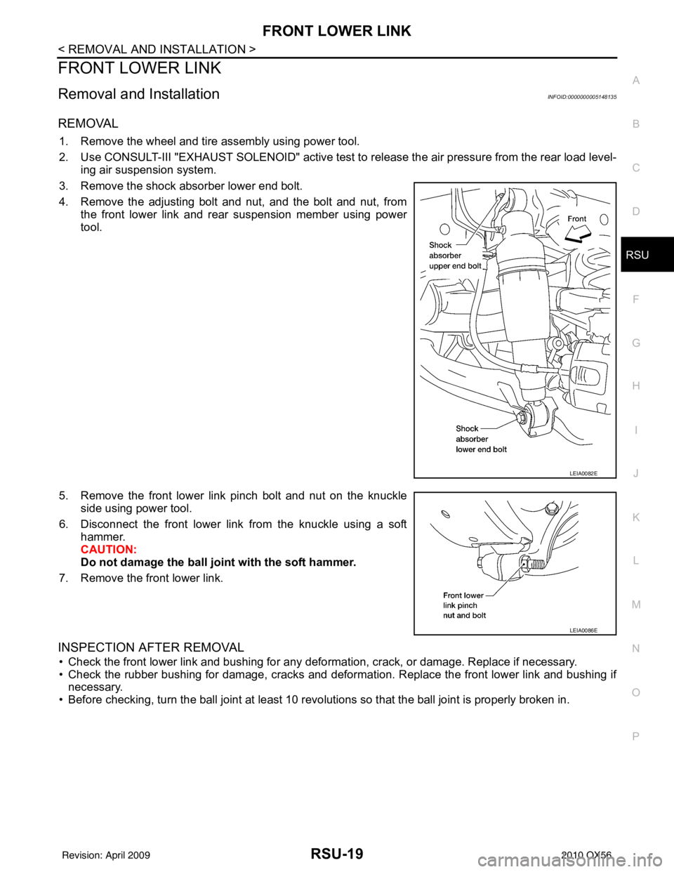
3. Remove the shock absorber lower end bolt.
4. Remove the adjusting bolt and nut, and the bolt and nut, from the front lower link and rear suspension member using power
tool.
5. Remove the front lower link pinch bolt and nut on the knuckle side using power tool.
6. Disconnect the front lower link from the knuckle using a soft hammer.
CAUTION:
Do not damage the ball joint with the soft hammer.
7. Remove the front lower link.
INSPECTION AFTER REMOVAL
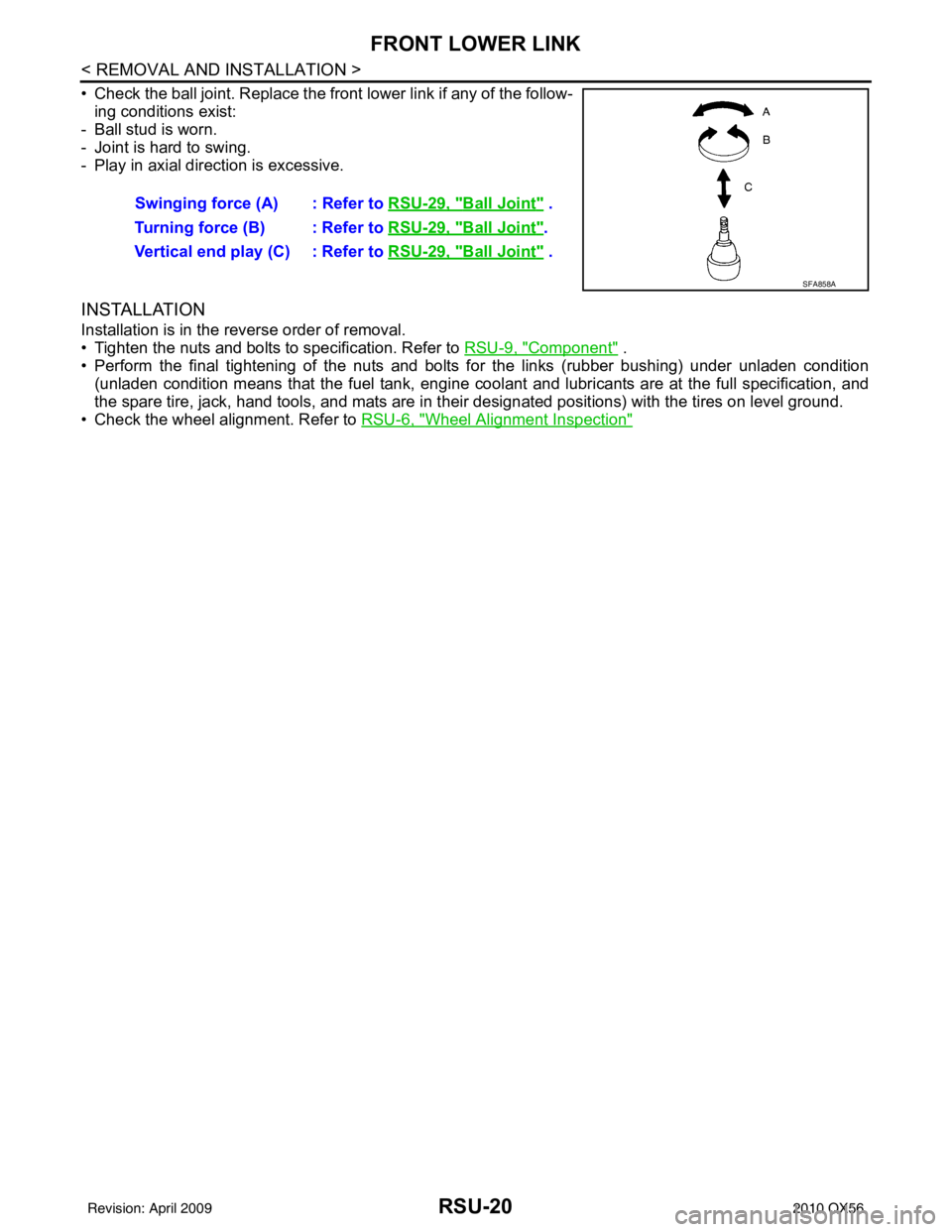
• Check the front lower link and bushing for any deforma tion, crack, or damage. Replace if necessary.
• Check the rubber bushing for damage, cracks and deforma tion. Replace the front lower link and bushing if
necessary.
• Before checking, turn the ball joint at least 10 revo lutions so that the ball joint is properly broken in.
LEIA0082E
LEIA0086E
Revision: April 20092010 QX56
Page 3207 of 4210
RSU-20
< REMOVAL AND INSTALLATION >
FRONT LOWER LINK
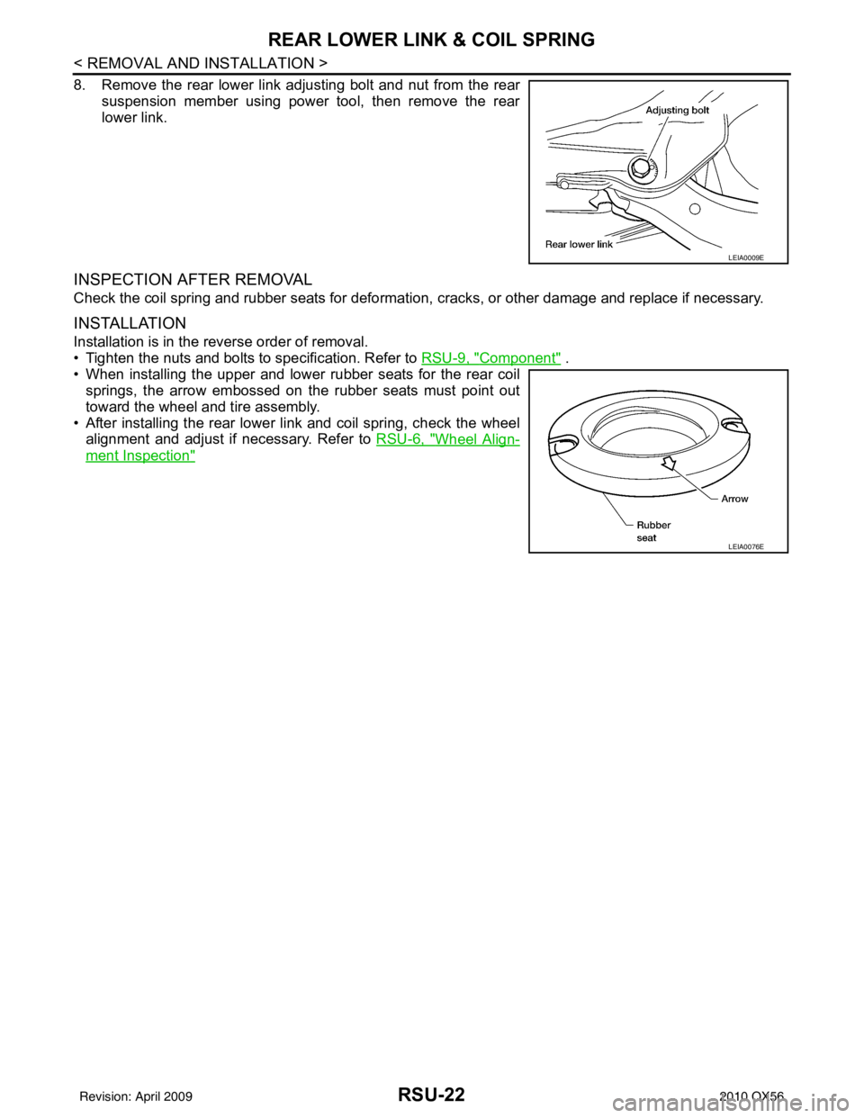
• Check the ball joint. Replace the front lower link if any of the follow-
ing conditions exist:
- Ball stud is worn.
- Joint is hard to swing.
- Play in axial direction is excessive.
INSTALLATION
Installation is in the reverse order of removal.
• Tighten the nuts and bolts to specification. Refer to RSU-9, "
Component" .
• Perform the final tightening of the nuts and bolts for the links (rubber bushing) under unladen condition (unladen condition means that the fuel tank, engine cool ant and lubricants are at the full specification, and
the spare tire, jack, hand tools, and mats are in t heir designated positions) with the tires on level ground.
• Check the wheel alignment. Refer to RSU-6, "
Wheel Alignment Inspection"
Swinging force (A) : Refer to RSU-29, "Ball Joint" .
Turning force (B) : Refer to RSU-29, "
Ball Joint".
Vertical end play (C) : Refer to RSU-29, "
Ball Joint" .
SFA858A
Revision: April 20092010 QX56
Page 3208 of 4210
REAR LOWER LINK & COIL SPRINGRSU-21
< REMOVAL AND INSTALLATION >
C
DF
G H
I
J
K L
M A
B
RSU
N
O P
REAR LOWER LINK & COIL SPRING
Removal and InstallationINFOID:0000000005148136
REMOVAL
1. Remove the wheel and tire assembly using power tool. Refer to WT-49, "Rotation" .
2. Use CONSULT-III "EXHAUST SOLENOID" active test to release the air pressure from the rear load level-
ing air suspension system.
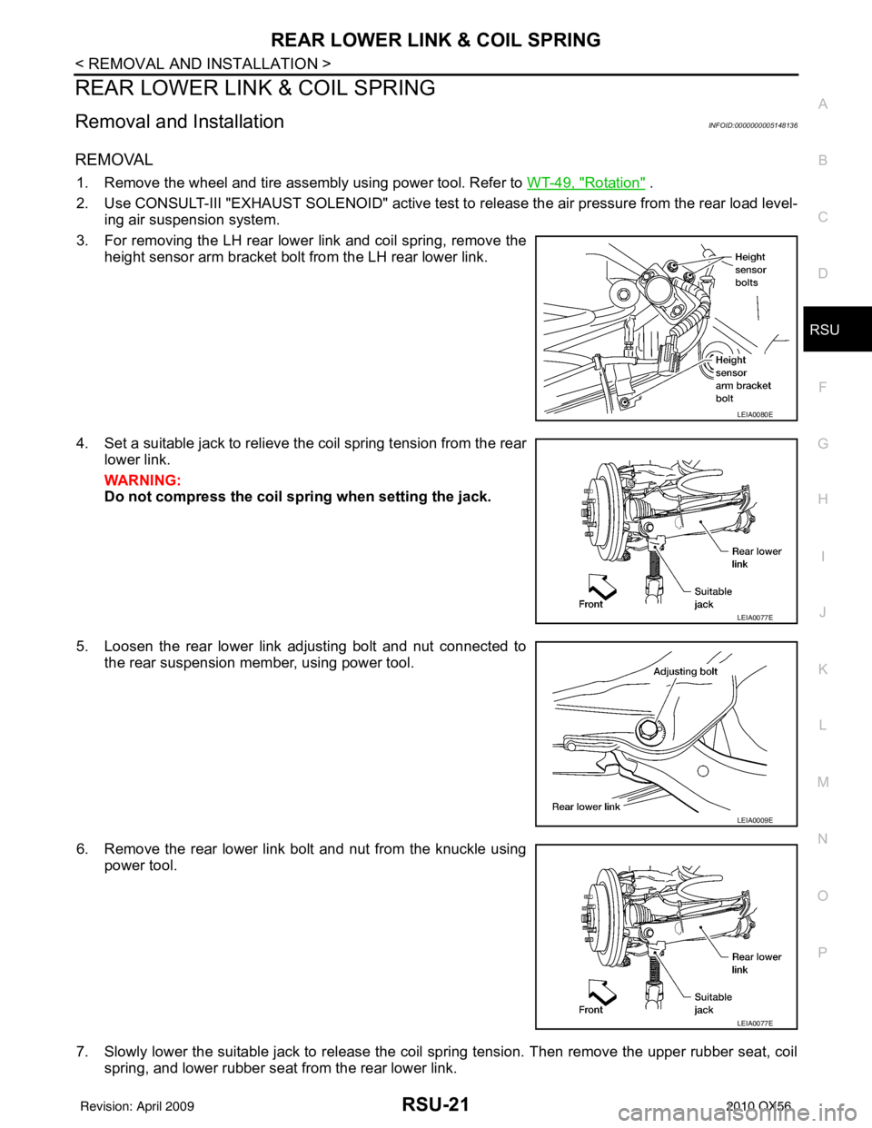
3. For removing the LH rear lower link and coil spring, remove the height sensor arm bracket bolt from the LH rear lower link.
4. Set a suitable jack to relieve the coil spring tension from the rear lower link.
WARNING:
Do not compress the coil sp ring when setting the jack.
5. Loosen the rear lower link adjusting bolt and nut connected to the rear suspension member, using power tool.
6. Remove the rear lower link bolt and nut from the knuckle using power tool.
7. Slowly lower the suitable jack to release the coil spring tension. Then remove the upper rubber seat, coil spring, and lower rubber seat from the rear lower link.
LEIA0080E
LEIA0077E
LEIA0009E
LEIA0077E
Revision: April 20092010 QX56
Page 3209 of 4210
RSU-22
< REMOVAL AND INSTALLATION >
REAR LOWER LINK & COIL SPRING
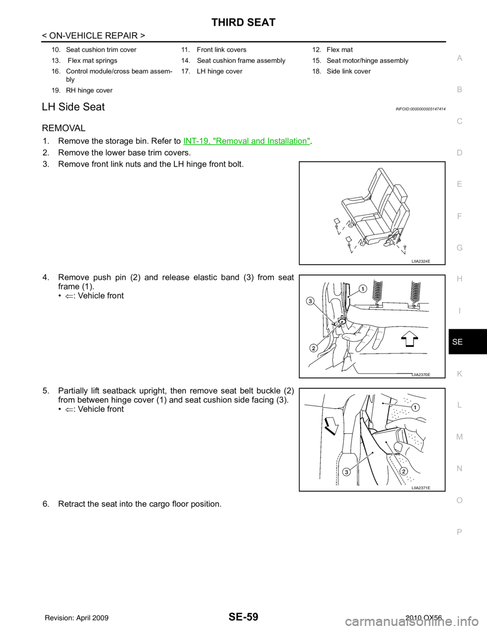
8. Remove the rear lower link adjusting bolt and nut from the rearsuspension member using power tool, then remove the rear
lower link.
INSPECTION AFTER REMOVAL
Check the coil spring and rubber seats for deformation, cracks, or other damage and replace if necessary.
INSTALLATION
Installation is in the reverse order of removal.
• Tighten the nuts and bolts to specification. Refer to RSU-9, "
Component" .
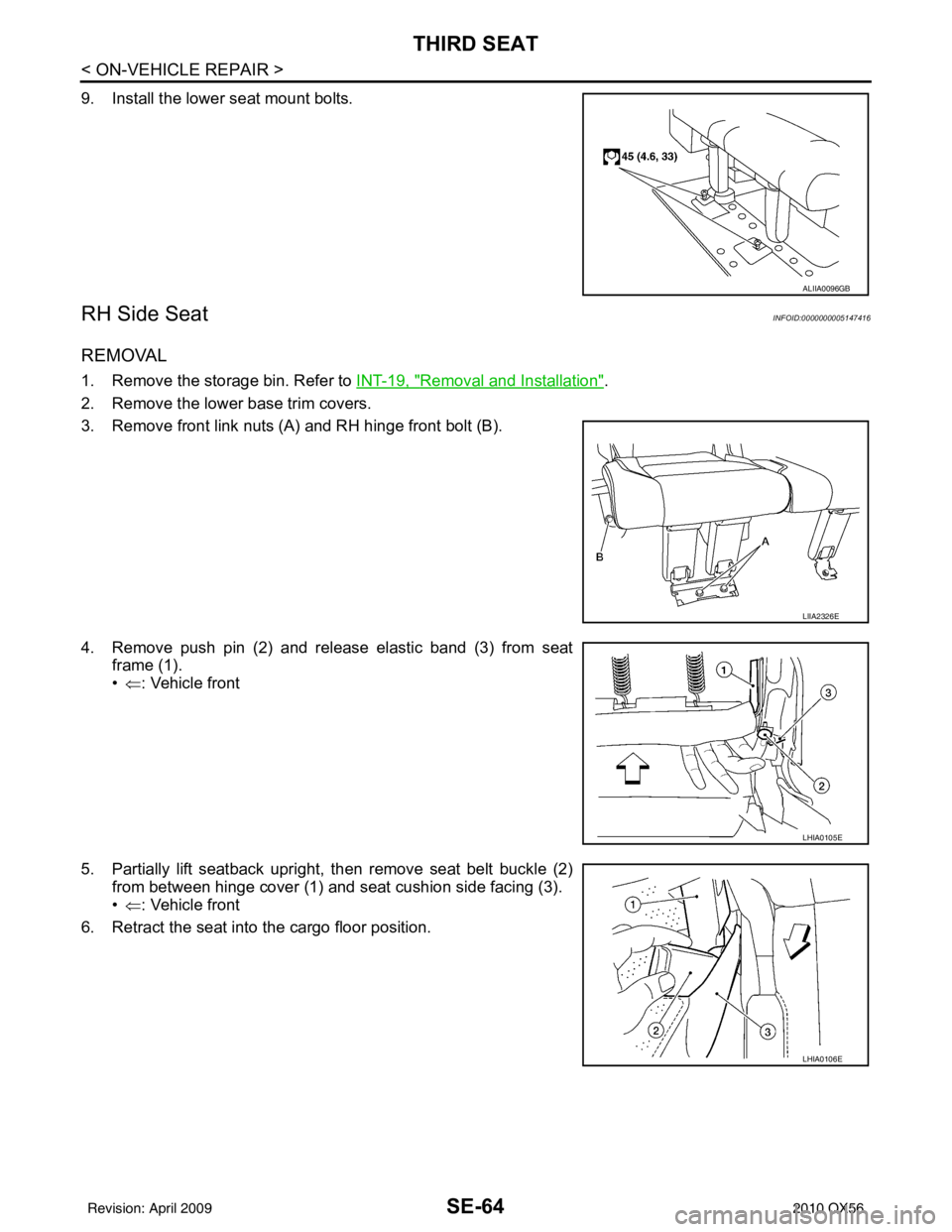
• When installing the upper and lower rubber seats for the rear coil springs, the arrow embossed on the rubber seats must point out
toward the wheel and tire assembly.
• After installing the rear lower link and coil spring, check the wheel alignment and adjust if necessary. Refer to RSU-6, "
Wheel Align-
ment Inspection"
LEIA0009E
LEIA0076E
Revision: April 20092010 QX56
Page 3328 of 4210
SE-56
< ON-VEHICLE REPAIR >
SECOND SEAT
Removal and Installation
INFOID:0000000005147412
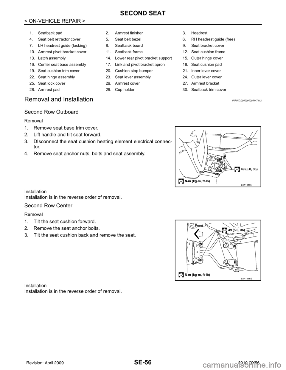
Second Row Outboard
Removal
1. Remove seat base trim cover.
2. Lift handle and tilt seat forward.
3. DIsconnect the seat cushion heating element electrical connec- tor.
4. Remove seat anchor nuts, bolts and seat assembly.
Installation
Installation is in the reverse order of removal.
Second Row Center
Removal
1. Tilt the seat cushion forward.
2. Remove the seat anchor bolts.
3. Tilt the seat cushion back and remove the seat.
Installation
Installation is in the reverse order of removal.
1. Seatback pad 2. Armrest finisher 3. Headrest
4. Seat belt retractor cover 5. Seat belt bezel 6. RH headrest guide (free)
7. LH headrest guide (locking) 8. Seatback board 9. Seat bracket cover
10. Armrest pivot bracket cover 11. Seatback frame 12. Seat cushion frame
13. Latch assembly 14. Lower rear pivot bracket support 15. Outer hinge cover
16. Center seat base assembly 17. Link and pivot bracket apron 18. Seat cushion pad
19. Seat cushion trim cover 20. Cushion stop bumper 21. Inner lever cover
22. Seat hinge assembly 23. Seat lever assembly 24. Outer lever cover
25. Seat lock cover 26. Armrest cover 27. Armrest bracket
28. Armrest pad 29. Cup holder 30. Seatback trim cover
LIIA1119E
LIIA1116E
Revision: April 20092010 QX56
Page 3331 of 4210
THIRD SEATSE-59
< ON-VEHICLE REPAIR >
C
DE
F
G H
I
K L
M A
B
SE
N
O P
LH Side SeatINFOID:0000000005147414
REMOVAL
1. Remove the storage bin. Refer to INT-19, "Removal and Installation".
2. Remove the lower base trim covers.
3. Remove front link nuts and the LH hinge front bolt.
4. Remove push pin (2) and release elastic band (3) from seat frame (1).
•⇐ : Vehicle front
5. Partially lift seatback upright, then remove seat belt buckle (2) from between hinge cover (1) and seat cushion side facing (3).
•⇐ : Vehicle front
6. Retract the seat into the cargo floor position.
10. Seat cushion trim cover 11. Front link covers 12. Flex mat
13. Flex mat springs 14. Seat cushion frame assembly 15. Seat motor/hinge assembly
16. Control module/cross beam assem- bly 17. LH hinge cover
18. Side link cover
19. RH hinge cover
LIIA2324E
LIIA2370E
LIIA2371E
Revision: April 20092010 QX56
Page 3336 of 4210
SE-64
< ON-VEHICLE REPAIR >
THIRD SEAT
9. Install the lower seat mount bolts.
RH Side SeatINFOID:0000000005147416
REMOVAL
1. Remove the storage bin. Refer to INT-19, "Removal and Installation".
2. Remove the lower base trim covers.
3. Remove front link nuts (A) and RH hinge front bolt (B).
4. Remove push pin (2) and release elastic band (3) from seat frame (1).
•⇐ : Vehicle front
5. Partially lift seatback upright, then remove seat belt buckle (2) from between hinge cover (1) and seat cushion side facing (3).
•⇐ : Vehicle front
6. Retract the seat into the cargo floor position.
ALIIA0096GB
LIIA2326E
LHIA0105E
LHIA0106E
Revision: April 20092010 QX56
Page 3346 of 4210
SE-74
< DISASSEMBLY AND ASSEMBLY >
SECOND SEAT
Second row center
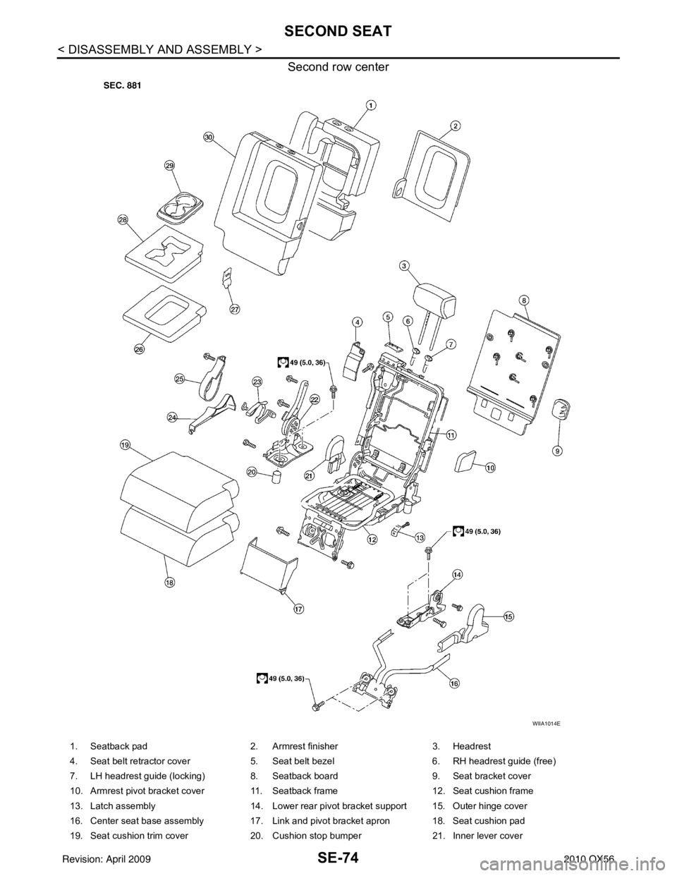
WIIA1014E
1. Seatback pad2. Armrest finisher 3. Headrest
4. Seat belt retractor cover 5. Seat belt bezel 6. RH headrest guide (free)
7. LH headrest guide (locking) 8. Seatback board 9. Seat bracket cover
10. Armrest pivot bracket cover 11. Seatback frame 12. Seat cushion frame
13. Latch assembly 14. Lower rear pivot bracket support 15. Outer hinge cover
16. Center seat base assembly 17. Link and pivot bracket apron 18. Seat cushion pad
19. Seat cushion trim cover 20. Cushion stop bumper 21. Inner lever cover
Revision: April 20092010 QX56