Page 2216 of 4210
LOWER LINKFSU-17
< REMOVAL AND INSTALLATION >
C
DF
G H
I
J
K L
M A
B
FSU
N
O P
LOWER LINK
Removal and InstallationINFOID:0000000005148116
REMOVAL
1. Remove the wheel and tire using power tool.
2. Remove lower shock absorber bolt.
3. Remove stabilizer bar connecting rod lower nut using power tool, then separate connecting rod from lower
link. Refer to FSU-15, "
Removal and Installation" .
4. Remove drive shaft nut, if equipped. Refer to FA X - 9 , "
Removal and Installation" .
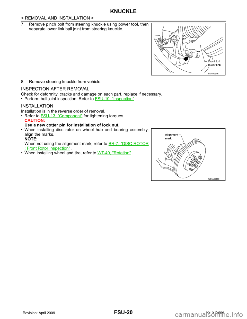
5. Remove pinch bolt from steering knuckle using power tool, then separate lower link ball joint from steering knuckle.
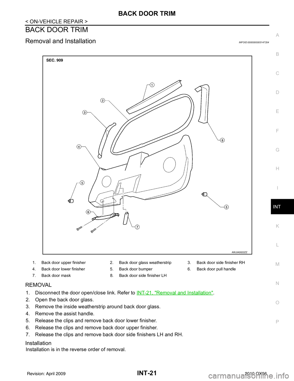
6. Remove lower link bolts (1) and nuts, then the lower link (2).
INSPECTION AFTER REMOVAL
Lower Link
Check for deformation and cracks. Replace if necessary.
Lower Link Bushing
Check for distortion and damage. Replace if necessary.
INSTALLATION
Installation is in the reverse order of removal.
• Tighten all nuts and bolts to specification. Refer to FSU-13, "
Component" .
• When installing wheel and tire, refer to WT-49, "
Rotation".
• After installation, check that the front wheel alignment is within specification. Refer to FSU-6, "
Front Wheel
Alignment" .
LEIA0097E
WEIA0153E
Revision: April 20092010 QX56
Page 2217 of 4210
FSU-18
< REMOVAL AND INSTALLATION >
UPPER BALL JOINT AND LOWER BALL JOINT
UPPER BALL JOINT AND LOWER BALL JOINT
Removal and InstallationINFOID:0000000005148117
The ball joints are part of the upper and lower links. Refer to FSU-16, "Removal and Installation" (upper link),
FSU-17, "
Removal and Installation" (lower link).
Revision: April 20092010 QX56
Page 2218 of 4210
KNUCKLEFSU-19
< REMOVAL AND INSTALLATION >
C
DF
G H
I
J
K L
M A
B
FSU
N
O P
KNUCKLE
Removal and InstallationINFOID:0000000005148118
REMOVAL
1. Remove wheel hub and bearing assembly. Refer to FAX-7, "Removal and Installation" .
• Disconnect wheel sensor harness connector. Do not remove wheel sensor from wheel hub and bearing
assembly for this procedure.
2. Remove steering outer socket from steering knuckle using Tool. CAUTION:
• Be careful not to damage ball joint boot.
• Temporarily tighten nut to prevent damage to threads andto prevent Tool from coming off.
3. Remove the coil spring and shock absorber assembly using power tool. Refer to FSU-14, "
Removal and
Installation" .
4. Support lower link using a suitable jack.
5. Remove cotter pin and nut from upper link ball joint and discard the cotter pin.
6. Separate upper link ball joint from steering knuckle using Tool.
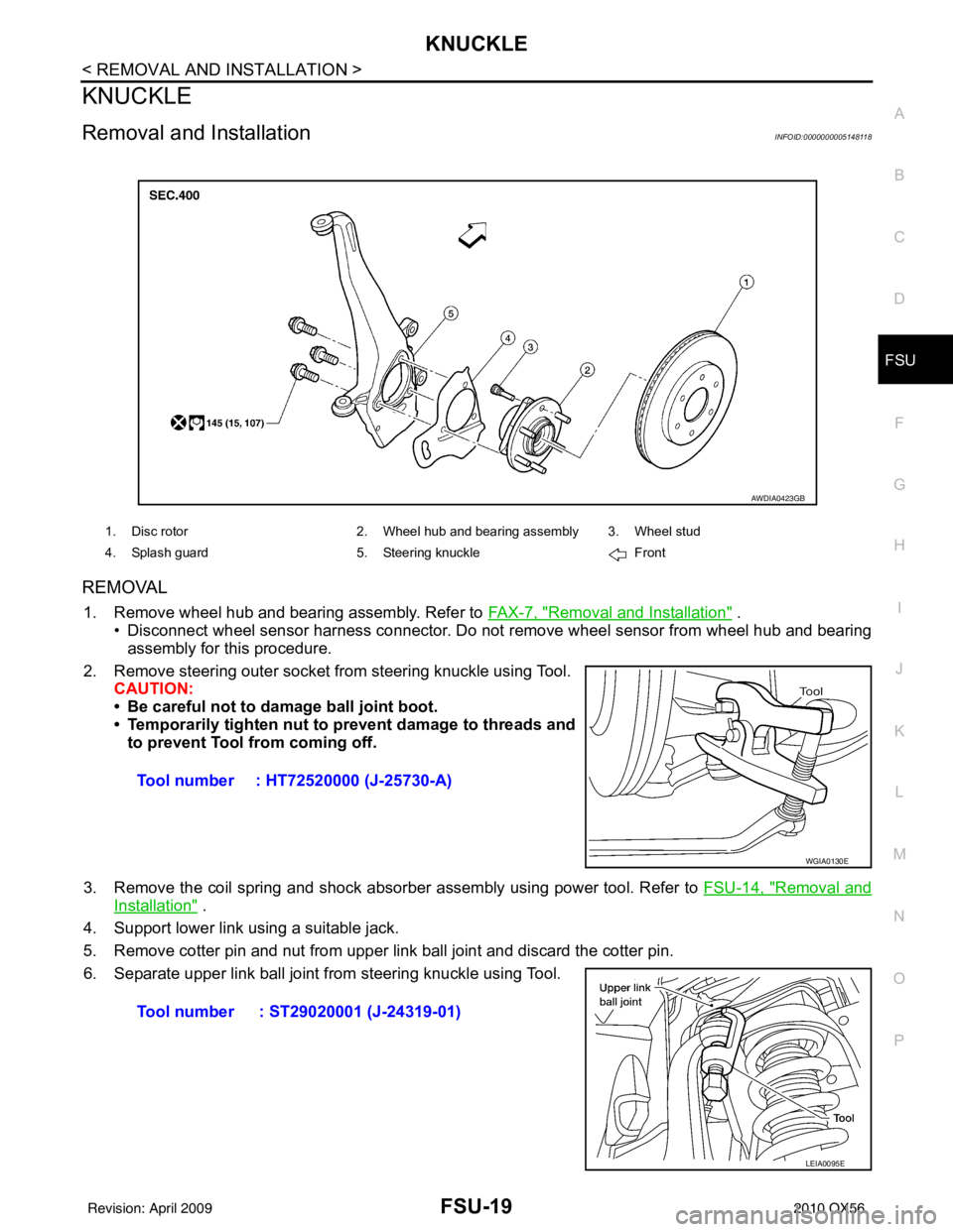
1. Disc rotor 2. Wheel hub and bearing assembly 3. Wheel stud
4. Splash guard 5. Steering knuckle Front
AWDIA0423GB
Tool number : HT72520000 (J-25730-A)
WGIA0130E
Tool number : ST29020001 (J-24319-01)
LEIA0095E
Revision: April 20092010 QX56
Page 2219 of 4210
FSU-20
< REMOVAL AND INSTALLATION >
KNUCKLE
7. Remove pinch bolt from steering knuckle using power tool, thenseparate lower link ball joint from steering knuckle.
8. Remove steering knuckle from vehicle.
INSPECTION AFTER REMOVAL
Check for deformity, cracks and damage on each part, replace if necessary.
• Perform ball joint inspection. Refer to FSU-10, "
Inspection" .
INSTALLATION
Installation is in the reverse order of removal.
• Refer to FSU-13, "
Component" for tightening torques.
CAUTION:
Use a new cotter pin for installation of lock nut.
• When installing disc rotor on wheel hub and bearing assembly, align the marks.
NOTE:
When not using the alignment mark, refer to BR-7, "
DISC ROTOR
: Front Rotor Inspection" .
• When installing wheel and tire, refer to WT-49, "
Rotation" .
LEIA0097E
WDIA0044E
Revision: April 20092010 QX56
Page 2389 of 4210
![INFINITI QX56 2010 Factory Service Manual BLOWER MOTOR CONTROL SYSTEMHAC-49
< COMPONENT DIAGNOSIS > [AUTOMATIC AIR CONDITIONER]
C
D
E
F
G H
J
K L
M A
B
HAC
N
O P
SYMPTOM: Blower motor operation is malfunctioning under starting
blower speed co](/manual-img/42/57032/w960_57032-2388.png "INFINITI QX56 2010 Factory Service Manual BLOWER MOTOR CONTROL SYSTEMHAC-49
< COMPONENT DIAGNOSIS > [AUTOMATIC AIR CONDITIONER]
C
D
E
F
G H
J
K L
M A
B
HAC
N
O P
SYMPTOM: Blower motor operation is malfunctioning under starting
blower speed co")
BLOWER MOTOR CONTROL SYSTEMHAC-49
< COMPONENT DIAGNOSIS > [AUTOMATIC AIR CONDITIONER]
C
D
E
F
G H
J
K L
M A
B
HAC
N
O P
SYMPTOM: Blower motor operation is malfunctioning under starting
blower speed control.
1.CHECK FUSES
Check 20A fuses [No. 24 and 27 (Located in the fuse and fusible link box)]. For fuse layout. Refer to PG-69,
"Terminal Arrangement".
Is the inspection result normal?
YES >> GO TO 2.
NO >> GO TO 7.
2.CHECK FRONT BLOWER MOTOR POWER SUPPLY CIRCUIT
1. Turn ignition switch OFF.
2. Disconnect front blower motor connector.
3. Turn ignition switch ON.
4. Press the A/C switch.
5. Press the front blower contro l "+" switch to maximum speed.
6. Check voltage between front blower motor harness connector
M62 terminal 2 and ground.
Is the inspection result normal?
YES >> GO TO 10.
NO >> GO TO 3.
3.CHECK FRONT BLOWER MOTOR RELAY (S WITCH SIDE) POWER SUPPLY CIRCUIT
1. Turn ignition switch OFF.
2. Disconnect front blower motor relay.
3. Turn ignition switch ON.
4. Check voltage between front blower motor relay harness con- nector M107 terminal 5 and ground.
Is the inspection result normal?
YES >> GO TO 4.
NO >> Repair harness or connector.
AWIIA0174GB
Fuses are good.
2 - Ground : Battery voltage
WJIA1331E
5 - Ground: Battery voltage
WJIA1359E
Revision: April 20092010 QX56
Page 2572 of 4210
INT-20
< ON-VEHICLE REPAIR >
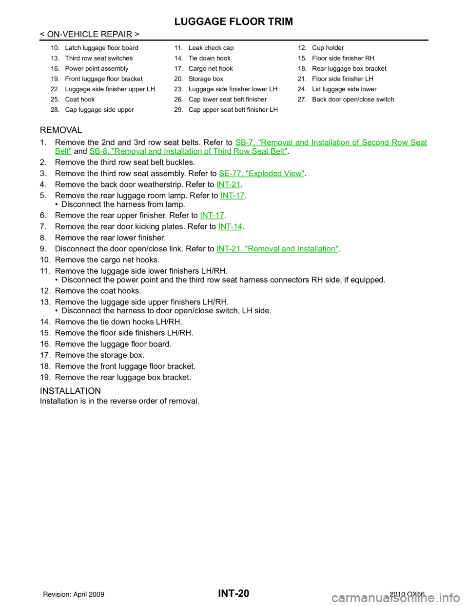
LUGGAGE FLOOR TRIM
REMOVAL
1. Remove the 2nd and 3rd row seat belts. Refer to SB-7, "Removal and Installation of Second Row Seat
Belt" and SB-8, "Removal and Installation of Third Row Seat Belt".
2. Remove the third row seat belt buckles.
3. Remove the third row seat assembly. Refer to SE-77, "
Exploded View".
4. Remove the back door weatherstrip. Refer to INT-21
.
5. Remove the rear luggage room lamp. Refer to INT-17
.
• Disconnect the harness from lamp.
6. Remove the rear upper finisher. Refer to INT-17
.
7. Remove the rear door kicking plates. Refer to INT-14
.
8. Remove the rear lower finisher.
9. Disconnect the door open/close link. Refer to INT-21, "
Removal and Installation".
10. Remove the cargo net hooks.
11. Remove the luggage side lower finishers LH/RH. • Disconnect the power point and the third row seat harness connectors RH side, if equipped.
12. Remove the coat hooks.
13. Remove the luggage side upper finishers LH/RH. • Disconnect the harness to door open/close switch, LH side.
14. Remove the tie down hooks LH/RH.
15. Remove the floor side finishers LH/RH.
16. Remove the luggage floor board.
17. Remove the storage box.
18. Remove the front luggage floor bracket.
19. Remove the rear luggage box bracket.
INSTALLATION
Installation is in the reverse order of removal.
10. Latch luggage floor board 11. Leak check cap 12. Cup holder
13. Third row seat switches 14. Tie down hook 15. Floor side finisher RH
16. Power point assembly 17. Cargo net hook 18. Rear luggage box bracket
19. Front luggage floor bracket 20. Storage box 21. Floor side finisher LH
22. Luggage side finisher upper LH 23. Luggage side finisher lower LH 24. Lid luggage side lower
25. Coat hook 26. Cap lower seat belt finisher 27. Back door open/close switch
28. Cap luggage side upper 29. Cap upper seat belt finisher LH
Revision: April 20092010 QX56
Page 2573 of 4210
BACK DOOR TRIMINT-21
< ON-VEHICLE REPAIR >
C
DE
F
G H
I
K L
M A
B
INT
N
O P
BACK DOOR TRIM
Removal and InstallationINFOID:0000000005147354
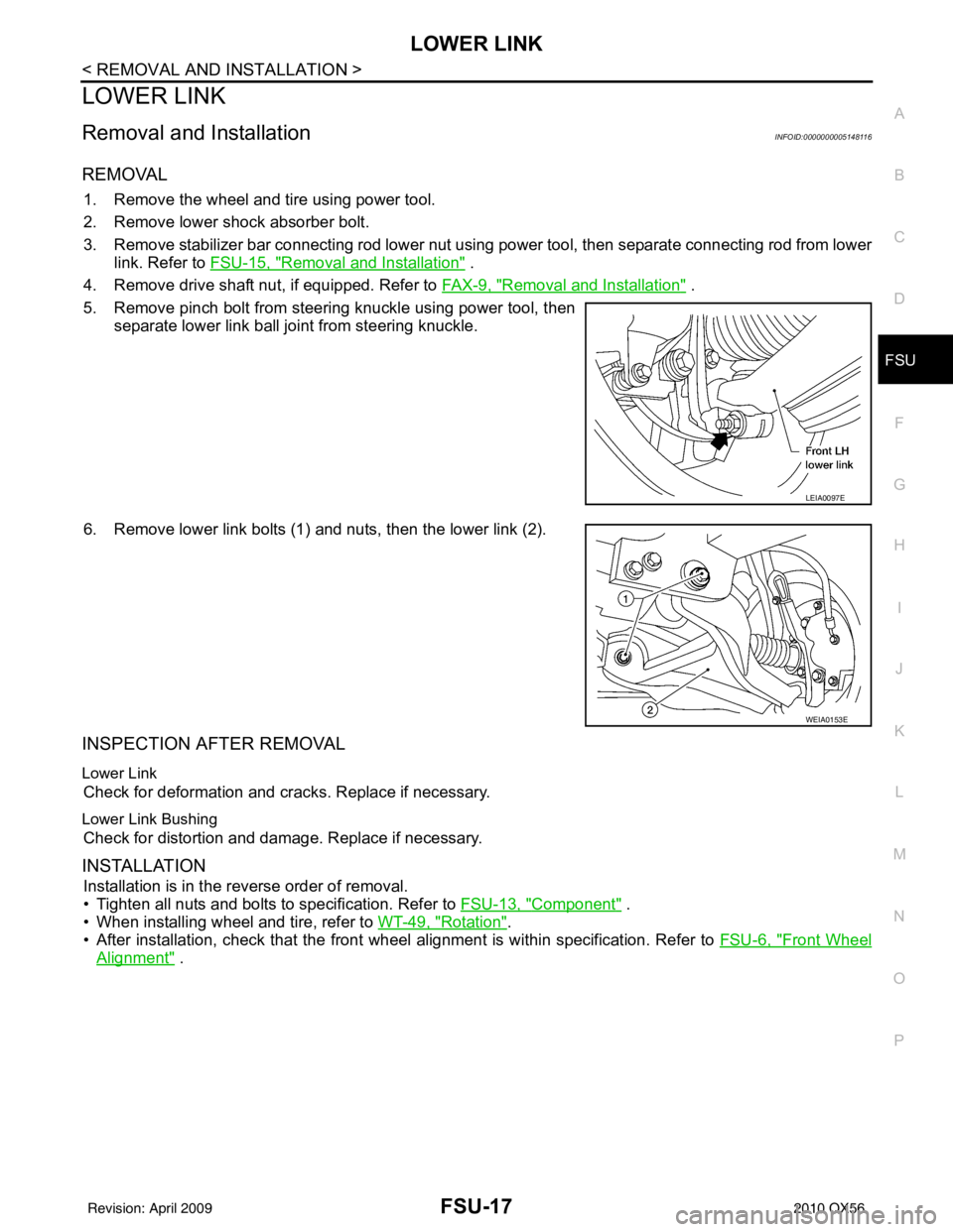
REMOVAL
1. Disconnect the door open/close link. Refer to INT-21, "Removal and Installation".
2. Open the back door glass.
3. Remove the inside weatherstrip around back door glass.
4. Remove the assist handle.
5. Release the clips and remove back door lower finisher.
6. Release the clips and remove back door upper finisher.
7. Release the clips and remove back door side finishers LH and RH.
Installation
Installation is in the reverse order of removal.
1. Back door upper finisher 2. Back door glass weatherstrip 3. Back door side finisher RH
4. Back door lower finisher 5. Back door bumper6. Back door pull handle
7. Back door mask 8. Back door side finisher LH
AWJIA0022ZZ
Revision: April 20092010 QX56
Page 2953 of 4210

PG
HARNESSPG-43
< COMPONENT DIAGNOSIS >
C
DE
F
G H
I
J
K L
B A
O P
N
A3 M6 W/10 : To E10
G4 M84 W/16 : To B101
A2 M7 B/5 : Passenger select unlock relay B2 M85 W/3 : Tilt motor
A3 M8 W/16 : To D2 B2 M86 W/2 : Tilt motor
A2 M9 BR/24 : To D1 B3 M87 B/5 : Rear power vent window relay (open)
A3 M10 Y/4 : To E29 B3 M89 B/5 : Rear power vent window relay (close)
A3 M11 B/1 : Parking brake switch A3 M91 W/16 : To E26
C3 M12 GR/6 : Key switch and ignition knob switch A2 M92 GR/6 : Power liftgate switch
D3 M13 BR/2 : Front passenger air bag OFF indicator D1 M93 W/24 : Display unit
A1 M14 B/2 : Diode-3 A2 M95 W/6 : Rear power vent window switch
B3 M15 W/4 : Steering lock solenoid A2 M96 BR/6 : Pedal adjusting switch
A2 M16 GR/6 : ADP steering switch C2 M98 W/16 : A/C and AV switch assembly
B2 M17 W/8 : Steering angle sensor C3 M99 BR/2 : Foot lamp LH
C2 M18 W/40 : BCM (body control module) F4 M100 BR/2 : Foot lamp RH
C2 M19 W/15 : BCM (body control module) E3 M104 W/4 : Aux jack
C2 M20 B/15 : BCM (body control module) F2 M105 Y/2 : Front passenger air bag module
C3 M21 W/4 : NATS antenna AMP. F2 M106 O/2 : Front passenger air bag module
C3 M22 W/16 : Data link connector F3 M107 B/5 : Front blower relay
B1 M23 W/12 : Combination meter D5 M108 B/6 : Yaw rate/ side/ decel G sensor
C1 M24 W/40 : Combination meter A1 M109 BR/2 : Front tweeter LH
F2 M25 B/4 : Remote keyless entry receiver D2 M110 BR/2 : Center speaker
B2 M26 W/6 : Ignition switch F2 M111 BR/2 : Front tweeter RH
B2 M28 W/16 : Combination switch C2 M112 BR/14 : BOSE speaker amp.
B2 M29 Y/6 : Combination switch C2 M113 BR/23 : BOSE speaker amp.
B3 M30 GR/8 : Combination switch A2 M116 GR/8 : Sonar system OFF switch
G4 M31 SMJ : To E152 B1 M118 B/2 : Front sonar buzzer
C3 M32 W/4 : In-vehicle sensor F2 M120 W/4 : Remote keyless entry receiver
B3 M33 W/32 : Automatic drive positioner control unit F4 M122 W/4 : Variable blower control (front)
B3 M34 W/16 : Automatic drive positioner control unit C3 M123 W/2 : Tire pressure warning check connector
C5 M35 Y/28 : Air bag diagnosis sensor unit D2 M139 B/2 : Diode-1
G4 M36 SMJ : To B149 D1 M140 B/2 : Diode-2
G3 M37 B/1 : Fuse block (J/B) C2 M141 GR/8 : 4WD shift switch
G3 M38 B/2 : Fuse block (J/B) E1 M142 B/6 : Mode door motor (front)
G3 M39 W/8 : Fuse block (J/B) E3 M143 B/6 : Air mix door motor (passenger)
A3 M40 SMJ : To B69 C1 M144 B/6 : Defroster door motor
D2 M42 W/20 : AV control unit E3 M146 GR/2 : Intake sensor
D2 M43 W/12 : AV control unit D3 M147B/6 : Air mix door motor (driver)
D2 M44 W/32 : AV control unit A3 M148 W/4 : Headlamp aiming switch
D2 M45 W/40 : AV control unit E3 M149 W/4 : Clock
B1 M47 B/2 : Sonar buzzer B1 M150 W/2 : Ignition keyhole illumination
D2 M49 B/26 : A/C auto amp. A3 M158 W/10 : To D3
D2 M50 L/26 : A/C auto amp. Console sub-harness
B3 M51 L/4 : Trailer tow relay 1 D4 M201 W/16 : To M56
B2 M52 W/2 : Combination switch D4 M202 BR/24 : To M64
D3 M53 B/3 : Front power socket LH D4 M203 W/12 : A/T shift selector
E3 M54 B/3 : Front power socket RH D5 M205 W/32 : DVD player
Revision: April 20092010 QX56