2010 INFINITI QX56 headlamp bulb
[x] Cancel search: headlamp bulbPage 1979 of 4210
EXL-3
C
DE
F
G H
I
J
K
M A
B
EXL
N
O P
PRECAUTION ....... .....................................143
PRECAUTIONS .............................................. ..143
Precaution for Supplemental Restraint System
(SRS) "AIR BAG" and "SEAT BELT PRE-TEN-
SIONER" ............................................................. ..
143
Precaution Necessary for Steering Wheel Rota-
tion After Battery Disconnect ............................... ..
143
General precautions for service operations ..........144
ON-VEHICLE REPAIR .... ...........................145
ADJUSTMENT AND INSPECTION ................ ..145
HEADLAMP ........................................................... ..145
HEADLAMP : Aiming Adjustment .........................145
FRONT FOG LAMP ............................................... ..146
FRONT FOG LAMP : Aiming Adjustment .............146
REMOVAL AND INSTALLATION .............148
HEADLAMP .................................................... ..148
Bulb Replacement .................................................148
Removal and Installation .......................................149
Disassembly and Assembly ................................ ..149
AUTO LIGHT SYSTEM ....................................151
Removal and Installation .......................................151
FRONT FOG LAMP ........................................152
Bulb Replacement ............................................... ..152
Removal and Installation .......................................152
LIGHTING & TURN SIGNAL SWITCH ...........154
Removal and Installation .......................................154
HAZARD SWITCH ..........................................155
Removal and Installation .......................................155
LICENSE PLATE LAMP .................................156
Bulb Replacement .................................................156
Removal and Installation .......................................156
STOP LAMP ....................................................157
Bulb Replacement .................................................157
Removal and Installation .......................................157
REAR COMBINATION LAMP .........................158
Bulb Replacement .................................................158
Removal and Installation .......................................158
SERVICE DATA AND SPECIFICATIONS
(SDS) ............... .......................................... .
159
BULB SPECIFICATIONS ................................159
Headlamp ............................................................ ..159
Exterior Lamp ........................................................159
Revision: April 20092010 QX56
Page 1984 of 4210
EXL-8
< FUNCTION DIAGNOSIS >
HEADLAMP
A Xenon type headlamp is adapted to the low beam headlamps. Xenon bulbs do not use a filament. Instead,
they produce light when a high voltage current is pa ssed between two tungsten electrodes through a mixture
of Xenon (an inert gas) and certain other metal halides. In addition to added lighting power, electronic control
of the power supply gives the headlamps stable quality and tone color. Following are some of the advantages
of the Xenon type headlamp.
• The light produced by the headlamps is a white color comparable to sunlight that is easy on the eyes.
• Light output is nearly double that of halogen headlamps, affording increased area of illumination.
• The light features a high relative spectral distribution at wavelengths to which the human eye is most sensi- tive. This means that even in the rain, more light is reflected back from the road surface toward the vehicle,
for added visibility.
• Power consumption is approximately 25 percent less than halogen headlamps, reducing battery load.
HIGH BEAM OPERATION/FLASH-TO-PASS OPERATION
With the combination switch (lighting and turn signal switch) in the 2ND position and placed in HIGH position,
the BCM receives input requesting the headlamp high beams to illuminate. The flash to pass feature can be
used any time and also sends a signal to the BCM. This input is communicated to the IPDM E/R via the CAN
communication lines. The CPU of the combination meter c ontrols the ON/OFF status off the HIGH BEAM indi-
cator. The CPU of the IPDM E/R controls the headlamp high relay coil which supplies power to the high beam
headlamps.
The combination meter receives a high beam request signal (ON) via the CAN communication lines and turns
the high beam indicator lamp ON.
EXTERIOR LAMP BATTERY SAVER CONTROL
With the combination switch (lighting and turn signal switch) in the 2nd position and the ignition switch is
turned from ON or ACC to OFF, the battery saver feature is activated.
Under this condition, the headlamps remain illuminated for 5 minutes unless the lighting switch position is
changed. If the lighting switch position is changed, then the headlamps are turned off.
This setting can be changed by CONSULT-III. Refer to BCS-22, "
HEADLAMP : CONSULT-III Function (BCM -
HEAD LAMP)".
Revision: April 20092010 QX56
Page 2007 of 4210
HEADLAMP (HI) CIRCUITEXL-31
< COMPONENT DIAGNOSIS >
C
DE
F
G H
I
J
K
M A
B
EXL
N
O P
1. Turn the ignition switch OFF.
2. Disconnect the front combination lamp connector E11 or E107.
3. Turn the ignition switch ON.
4. Turn the high beam headlamps ON.
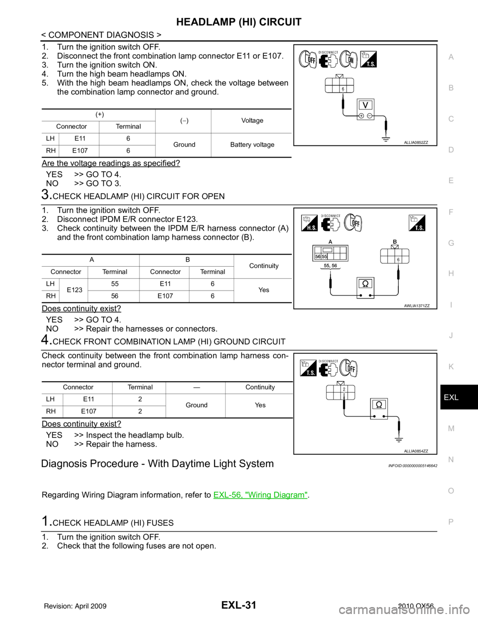
5. With the high beam headlamps ON, check the voltage between the combination lamp connector and ground.
Are the voltage readings as specified?
YES >> GO TO 4.
NO >> GO TO 3.
3.CHECK HEADLAMP (HI) CIRCUIT FOR OPEN
1. Turn the ignition switch OFF.
2. Disconnect IPDM E/R connector E123.
3. Check continuity between the IPDM E/R harness connector (A) and the front combination lamp harness connector (B).
Does continuity exist?
YES >> GO TO 4.
NO >> Repair the harnesses or connectors.
4.CHECK FRONT COMBINATION LAMP (HI) GROUND CIRCUIT
Check continuity between the front combination lamp harness con-
nector terminal and ground.
Does continuity exist?
YES >> Inspect the headlamp bulb.
NO >> Repair the harness.
Diagnosis Procedure - With Daytime Light SystemINFOID:0000000005146642
Regarding Wiring Diagram information, refer to EXL-56, "Wiring Diagram".
1.CHECK HEADLAMP (HI) FUSES
1. Turn the ignition switch OFF.
2. Check that the following fuses are not open.
(+) (−)Voltage
Connector Terminal
LH E11 6 Ground Battery voltage
RH E107 6
ALLIA0852ZZ
AB Continuity
Connector Terminal Connector Terminal
LH E123 55
E11 6
Ye s
RH 56E107 6
AWLIA1371ZZ
Connector Terminal —Continuity
LH E11 2
Ground Yes
RH E107 2
ALLIA0854ZZ
Revision: April 20092010 QX56
Page 2008 of 4210
EXL-32
< COMPONENT DIAGNOSIS >
HEADLAMP (HI) CIRCUIT
Is the fuse open?
YES >> Repair the harness and replace the fuse.
NO >> GO TO 2.
2.CHECK HEADLAMP (HI) OUTPUT VOLTAGE
1. Turn the ignition switch OFF.
2. Disconnect the front combination lamp connector E6 or E108.
3. Turn the ignition switch ON.
4. Turn the high beam headlamps ON.
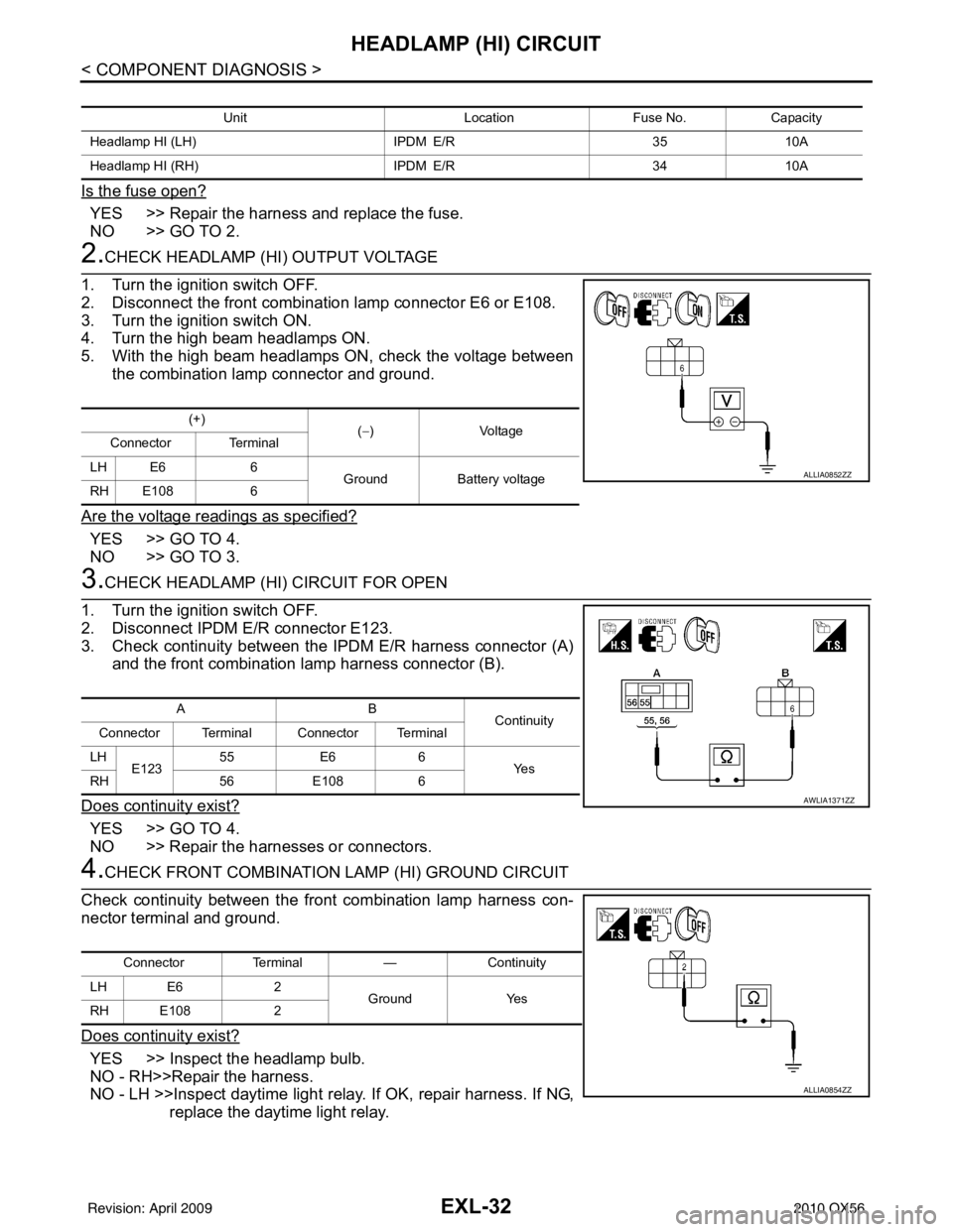
5. With the high beam headlamps ON, check the voltage between the combination lamp connector and ground.
Are the voltage readings as specified?
YES >> GO TO 4.
NO >> GO TO 3.
3.CHECK HEADLAMP (HI) CIRCUIT FOR OPEN
1. Turn the ignition switch OFF.
2. Disconnect IPDM E/R connector E123.
3. Check continuity between the IPDM E/R harness connector (A) and the front combination lamp harness connector (B).
Does continuity exist?
YES >> GO TO 4.
NO >> Repair the harnesses or connectors.
4.CHECK FRONT COMBINATION LAMP (HI) GROUND CIRCUIT
Check continuity between the front combination lamp harness con-
nector terminal and ground.
Does continuity exist?
YES >> Inspect the headlamp bulb.
NO - RH>>Repair the harness.
NO - LH >>Inspect daytime light rela y. If OK, repair harness. If NG,
replace the daytime light relay.
Unit LocationFuse No.Capacity
Headlamp HI (LH) IPDM E/R3510A
Headlamp HI (RH) IPDM E/R3410A
(+)
(−)Voltage
Connector Terminal
LH E6 6 GroundBattery voltage
RH E108 6
ALLIA0852ZZ
AB
Continuity
Connector Terminal Connector Terminal
LH E123 55
E66
Ye s
RH 56E108 6
AWLIA1371ZZ
Connector Terminal —Continuity
LH E6 2
Ground Yes
RH E108 2
ALLIA0854ZZ
Revision: April 20092010 QX56
Page 2010 of 4210
EXL-34
< COMPONENT DIAGNOSIS >
HEADLAMP (LO) CIRCUIT
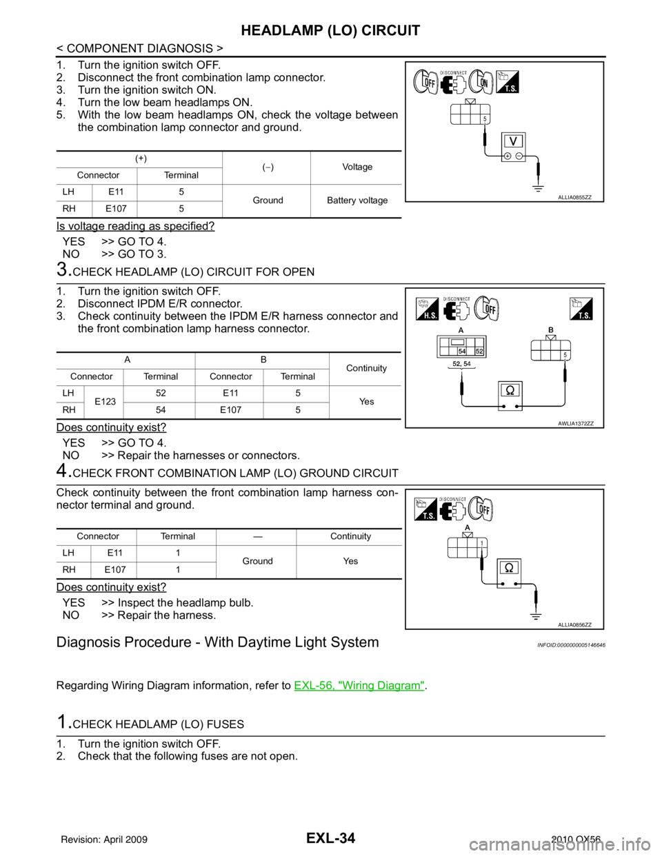
1. Turn the ignition switch OFF.
2. Disconnect the front combination lamp connector.
3. Turn the ignition switch ON.
4. Turn the low beam headlamps ON.
5. With the low beam headlamps ON, check the voltage betweenthe combination lamp connector and ground.
Is voltage reading as specified?
YES >> GO TO 4.
NO >> GO TO 3.
3.CHECK HEADLAMP (LO) CIRCUIT FOR OPEN
1. Turn the ignition switch OFF.
2. Disconnect IPDM E/R connector.
3. Check continuity between the IPDM E/R harness connector and
the front combination lamp harness connector.
Does continuity exist?
YES >> GO TO 4.
NO >> Repair the harnesses or connectors.
4.CHECK FRONT COMBINATION LAMP (LO) GROUND CIRCUIT
Check continuity between the front combination lamp harness con-
nector terminal and ground.
Does continuity exist?
YES >> Inspect the headlamp bulb.
NO >> Repair the harness.
Diagnosis Procedure - With Daytime Light SystemINFOID:0000000005146646
Regarding Wiring Diagram information, refer to EXL-56, "Wiring Diagram".
1.CHECK HEADLAMP (LO) FUSES
1. Turn the ignition switch OFF.
2. Check that the following fuses are not open.
(+) (−)V olt a ge
Connector Terminal
LH E11 5
Ground Battery voltage
RH E107 5
ALLIA0855ZZ
AB
Continuity
Connector Terminal Connector Terminal
LH E123 52
E11 5
Ye s
RH 54E107 5
AWLIA1372ZZ
Connector Terminal —Continuity
LH E11 1
Ground Yes
RH E107 1
ALLIA0856ZZ
Revision: April 20092010 QX56
Page 2011 of 4210
HEADLAMP (LO) CIRCUITEXL-35
< COMPONENT DIAGNOSIS >
C
DE
F
G H
I
J
K
M A
B
EXL
N
O P
Is the fuse open?
YES >> Repair the harness and replace the fuse.
NO >> GO TO 2.
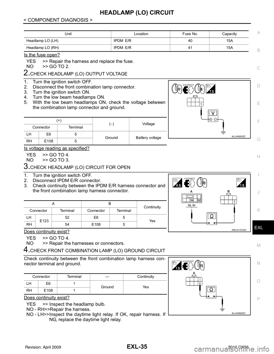
2.CHECK HEADLAMP (LO) OUTPUT VOLTAGE
1. Turn the ignition switch OFF.
2. Disconnect the front combination lamp connector.
3. Turn the ignition switch ON.
4. Turn the low beam headlamps ON.
5. With the low beam headlamps ON, check the voltage between the combination lamp connector and ground.
Is voltage reading as specified?
YES >> GO TO 4.
NO >> GO TO 3.
3.CHECK HEADLAMP (LO) CIRCUIT FOR OPEN
1. Turn the ignition switch OFF.
2. Disconnect IPDM E/R connector.
3. Check continuity between the IPDM E/R harness connector and the front combination lamp harness connector.
Does continuity exist?
YES >> GO TO 4.
NO >> Repair the harnesses or connectors.
4.CHECK FRONT COMBINATION LAMP (LO) GROUND CIRCUIT
Check continuity between the front combination lamp harness con-
nector terminal and ground.
Does continuity exist?
YES >> Inspect the headlamp bulb.
NO - RH>>Repair the harness.
NO - LH>>Inspect the daytime light relay. If OK, repair harness. If
NG, replace the daytime light relay.
Unit LocationFuse No.Capacity
Headlamp LO (LH) IPDM E/R4015A
Headlamp LO (RH) IPDM E/R4115A
(+)
(−)Voltage
Connector Terminal
LH E6 5
Ground Battery voltage
RH E108 5
ALLIA0855ZZ
AB
Continuity
Connector Terminal Connector Terminal
LH E123 52
E6 5
Ye s
RH 54E108 5
AWLIA1372ZZ
Connector Terminal —Continuity
LH E6 1
Ground Yes
RH E108 1
ALLIA0856ZZ
Revision: April 20092010 QX56
Page 2112 of 4210
EXL-136
< SYMPTOM DIAGNOSIS >
EXTERIOR LIGHTING SYSTEM SYMPTOMS
SYMPTOM DIAGNOSIS
EXTERIOR LIGHTING SYSTEM SYMPTOMS
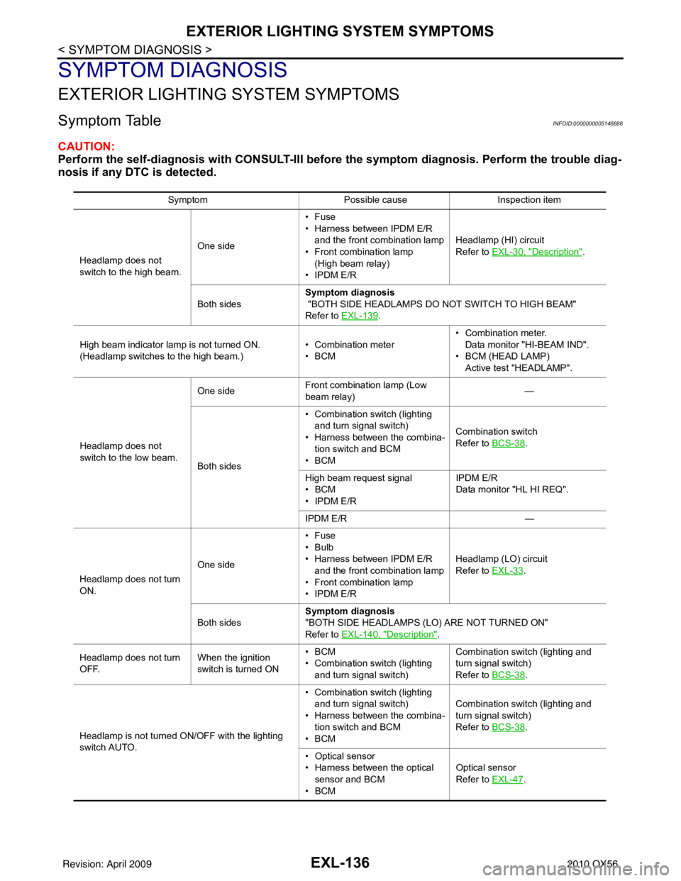
Symptom TableINFOID:0000000005146686
CAUTION:
Perform the self-diagnosis with CONSULT-III before the symptom diagnosis. Perform the trouble diag-
nosis if any DTC is detected.
Symptom Possible causeInspection item
Headlamp does not
switch to the high beam. One side•Fuse
• Harness between IPDM E/R
and the front combination lamp
• Front combination lamp
(High beam relay)
• IPDM E/R Headlamp (HI) circuit
Refer to EXL-30, "
Description".
Both sides Symptom diagnosis
"BOTH SIDE HEADLAMPS DO NOT SWITCH TO HIGH BEAM"
Refer to
EXL-139
.
High beam indicator lamp is not turned ON.
(Headlamp switches to the high beam.) • Combination meter
•BCM• Combination meter.
Data monitor "HI-BEAM IND".
• BCM (HEAD LAMP) Active test "HEADLAMP".
Headlamp does not
switch to the low beam. One side
Front combination lamp (Low
beam relay)
—
Both sides • Combination switch (lighting
and turn signal switch)
• Harness between the combina-
tion switch and BCM
•BCM Combination switch
Refer to BCS-38
.
High beam request signal
•BCM
• IPDM E/R IPDM E/R
Data monitor "HL HI REQ".
IPDM E/R —
Headlamp does not turn
ON. One side•Fuse
•Bulb
• Harness between IPDM E/R
and the front combination lamp
• Front combination lamp
• IPDM E/R Headlamp (L
O) circuit
Refer to EXL-33
.
Both sides Symptom diagnosis
"BOTH SIDE HEADLAMPS (LO) ARE NOT TURNED ON"
Refer to
EXL-140, "
Description".
Headlamp does not turn
OFF. When the ignition
switch is turned ON•BCM
• Combination switch (lighting
and turn signal switch) Combination switch (lighting and
turn signal switch)
Refer to BCS-38
.
Headlamp is not turned ON/OFF with the lighting
switch AUTO. • Combination switch (lighting
and turn signal switch)
• Harness between the combina-
tion switch and BCM
•BCM Combination switch (lighting and
turn signal switch)
Refer to BCS-38
.
• Optical sensor
• Harness between the optical sensor and BCM
•BCM Optical sensor
Refer to EXL-47
.
Revision: April 20092010 QX56
Page 2114 of 4210

EXL-138
< SYMPTOM DIAGNOSIS >
NORMAL OPERATING CONDITION
NORMAL OPERATING CONDITION
DescriptionINFOID:0000000005146687
XENON HEADLAMPS
The brightness and color of the light may vary slightly immediately after turning the headlamp ON. This condi-
tionwill remain until the xenon bulb becomes stable. This is normal.
• Illumination time lag may occur between right and left. This is normal.
AUTO LIGHT SYSTEM
The auto light system may not turn the headlamp ON/OF F immediately after passing a dark area or a bright
area (short tunnel, sky bridge, shadowed area etc.). This is normal.
Revision: April 20092010 QX56