2010 INFINITI QX56 Drive Belts
[x] Cancel search: Drive BeltsPage 750 of 4210

CHG-8
< COMPONENT DIAGNOSIS >
CHARGING SYSTEM PRELIMINARY INSPECTION
COMPONENT DIAGNOSIS
CHARGING SYSTEM PRELIMINARY INSPECTION
Inspection ProcedureINFOID:0000000005146557
1.CHECK BATTERY TERMINALS CONNECTION
Check if battery terminals are clean and tight.
Is the inspection result normal?
YES >> GO TO 2.
NO >> Repair battery terminals connection.
2.CHECK FUSE
Check for blown fuse and fusible link.
Is the inspection result normal?
YES >> GO TO 3.
NO >> Be sure to eliminate cause of malfunction before installing new fuse or fusible link.
3.CHECK GENERATOR GROUND TERMINAL CONNECTION
Verify connector E206 terminal 5 (generator ground harness) is clean and tight.
Is the inspection result normal?
YES >> GO TO 4.
NO >> Repair connection.
4.CHECK DRIVE BELT TENSION
Check drive belt tension. Refer to EM-13, "
Checking Drive Belts".
Is the inspection result normal?
YES >> Inspection End.
NO >> Repair as needed.
Unit Power source (Power supply terminals) Fuse or Fusible Link
Generator Battery (terminal 3)
Fuse 30
Battery (terminal 1) Fusible Link A
Combination meter Ignition switch ON (terminal 2) Fuse 14
Revision: April 20092010 QX56
Page 763 of 4210

CHG
GENERATORCHG-21
< ON-VEHICLE REPAIR >
C
DE
F
G H
I
J
K L
B A
O P
N
ON-VEHICLE REPAIR
GENERATOR
Removal and InstallationINFOID:0000000005146567
REMOVAL
1. Disconnect the negative battery terminal. Refer to
PG-74, "Removal and Installation".
2. Remove the fan shroud. Refer to CO-15, "
Removal and Installation".
3. Remove the drive belt. Refer to EM-13, "
Removal and Installation".
4. Remove lower bracket, using power tools.
5. Remove the generator upper bolt, using power tools.
6. Disconnect the generator harness connectors.
7. Remove the generator.
INSTALLATION
Installation is in the reverse order of removal.
• Install the generator and check the t ension of the drive belt. Refer to EM-13, "
Checking Drive Belts".
CAUTION:
Tighten terminal nut carefully.
WKIA1390E
Terminal nut : 10.8 N·m (1.1 kg-m, 8 ft-lb)
Revision: April 20092010 QX56
Page 775 of 4210

ENGINE COOLANTCO-11
< ON-VEHICLE MAINTENANCE >
C
DE
F
G H
I
J
K L
M A
CO
NP
O
Inspect the radiator cap.
NOTE:
Thoroughly wipe out the radiator filler
neck to remove any waxy resi-
due or foreign material.
• Replace the cap if the metal plunger cannot be seen around the edge of the black rubber gasket.
• Replace the cap if deposits of waxy residue or other foreign mate- rial are on the black rubber gasket or the metal retainer.
• Pull negative-pressure valve to open it and make sure that it closes completely when released.
• Make sure that there is no dirt or damage on the valve seat of radi-
ator cap negative-pressure valve.
• Make sure that there are no unusualness in the opening and clos- ing conditions of negative-pressure valve.
Changing Engine CoolantINFOID:0000000005149042
WARNING:
• To avoid being scalded, never change the coolant when the engine is hot.
• Wrap a thick cloth around the cap to carefully remo ve the cap. First, turn the cap a quarter of a turn
to release any built-up pressure, then push down and turn the cap all the way to remove it.
DRAINING ENGINE COOLANT
1. Turn ignition switch ON and set temperature control lever all the way to HOT position or the highest tem-
perature position. Wait 10 seconds and turn ignition switch OFF.
2. Remove the engine front undercover using power tool.
3. Open the radiator drain plug at the bottom of the radiator, and remove the radiator filler cap. This is the only step required
when partially draining the cooling system (radiator only).
CAUTION:
Do not to allow the coolant to contact the drive belts.
4. When draining all of the coolant in the system for engine removal or repair, it is necessary to drain the cylinder block.
Remove the RH cylinder block drain plug to drain the right bank
and the oil cooler hose to drain the left bank as shown.
PBIC2816E
SMA967B
WBIA0391E
PBIC0146E
Revision: April 20092010 QX56
Page 780 of 4210

CO-16
< ON-VEHICLE REPAIR >
RADIATOR
5. Disconnect the radiator lower hose from the radiator.CAUTION:
Do not allow coolant to contact drive belts.
6. Remove the lower radiator shroud. • Release the tabs, pull lower radiator shroud rearwards anddown to remove.
7. Disconnect the radiator upper hose and the coolant reservoir hose from the radiator. CAUTION:
Do not allow coolant to contact drive belt.
8. Remove the radiator shroud upper bolts and remove the radiator shroud upper (A).
9. Remove the upper radiator mounting bolts and rubbers.
10. Remove the A/C condenser bolts and brackets. NOTE:
Lift A/C condenser up and forward to remove from radiator.
11. Remove A/T oil cooler bolts and oil cooler from radiator and position aside.
WBIA0407E
WBIA0695E
WBIA0395E
WBIA0396E
Revision: April 20092010 QX56
Page 1852 of 4210

EM-1
ENGINE
C
DE
F
G H
I
J
K L
M
SECTION EM
A
EM
N
O P
CONTENTS
ENGINE MECHANICAL
PRECAUTION ....... ........................................3
PRECAUTIONS .............................................. .....3
Precaution for Supplemental Restraint System
(SRS) "AIR BAG" and "SEAT BELT PRE-TEN-
SIONER" ............................................................. ......
3
Precaution Necessary for Steering Wheel Rota-
tion After Battery Disconnect ............................... ......
3
Precaution for Drain Engine Coolant .........................4
Precaution for Disconnecting Fuel Piping .................4
Precaution for Removal and Disassembly ................4
Precaution for Inspection, Repair and Replace-
ment .................................................................... ......
4
Precaution for Assembly and Installation ..................4
Parts Requiring Angular Tightening ..........................4
Precaution for Liquid Gasket ............................... ......5
PREPARATION ............................................6
PREPARATION .............................................. .....6
Special Service Tool ........................................... ......6
Commercial Service Tool ..........................................8
FUNCTION DIAGNOSIS ..............................10
NOISE, VIBRATION, AND HARSHNESS
(NVH) TROUBLESHOOTING ........................ ....
10
NVH Troubleshooting - Engine Noise ................. ....10
Use the Chart Below to Help You Find the Cause
of the Symptom .......................................................
11
ON-VEHICLE MAINTENANCE ....................13
DRIVE BELTS ................................................ ....13
Exploded View .................................................... ....13
Checking Drive Belts ...............................................13
Removal and Installation .........................................13
Drive Belt Auto Tensioner and Idler Pulley ......... ....14
AIR CLEANER FILTER ......................................15
Exploded View .................................................... ....15
Removal and Installation (Viscous paper type) .......15
SPARK PLUG ...................................................16
Exploded View ..................................................... ....16
Removal and Installation .........................................16
CAMSHAFT VALVE CLEARANCE ..................18
Valve Clearance ......................................................18
COMPRESSION PRESSURE ...........................23
Checking Compression Pressure ............................23
ON-VEHICLE REPAIR .................................24
ENGINE ROOM COVER ...................................24
Removal and Installation ..................................... ....24
AIR CLEANER AND AIR DUCT .......................25
Exploded View .........................................................25
Removal and Installation .........................................25
INTAKE MANIFOLD .........................................26
Exploded View .........................................................26
Removal and Installation .........................................26
EXHAUST MANIFOLD AND THREE WAY
CATALYST ........................................................
30
Exploded View .........................................................30
Removal and Installation .........................................30
OIL PAN AND OIL STRAINER .........................33
Exploded View .........................................................33
Removal and Installation .........................................33
IGNITION COIL .................................................37
Exploded View .........................................................37
Removal and Installation .........................................37
ROCKER COVER .............................................38
Exploded View .........................................................38
Removal and Installation .........................................38
FUEL INJECTOR AND FUEL TUBE ................40
Exploded View .........................................................40
Removal and Installation .........................................40
Revision: April 20092010 QX56
Page 1863 of 4210
EM-12
< FUNCTION DIAGNOSIS >
NOISE, VIBRATION, AND HARSHNESS (NVH) TROUBLESHOOTING
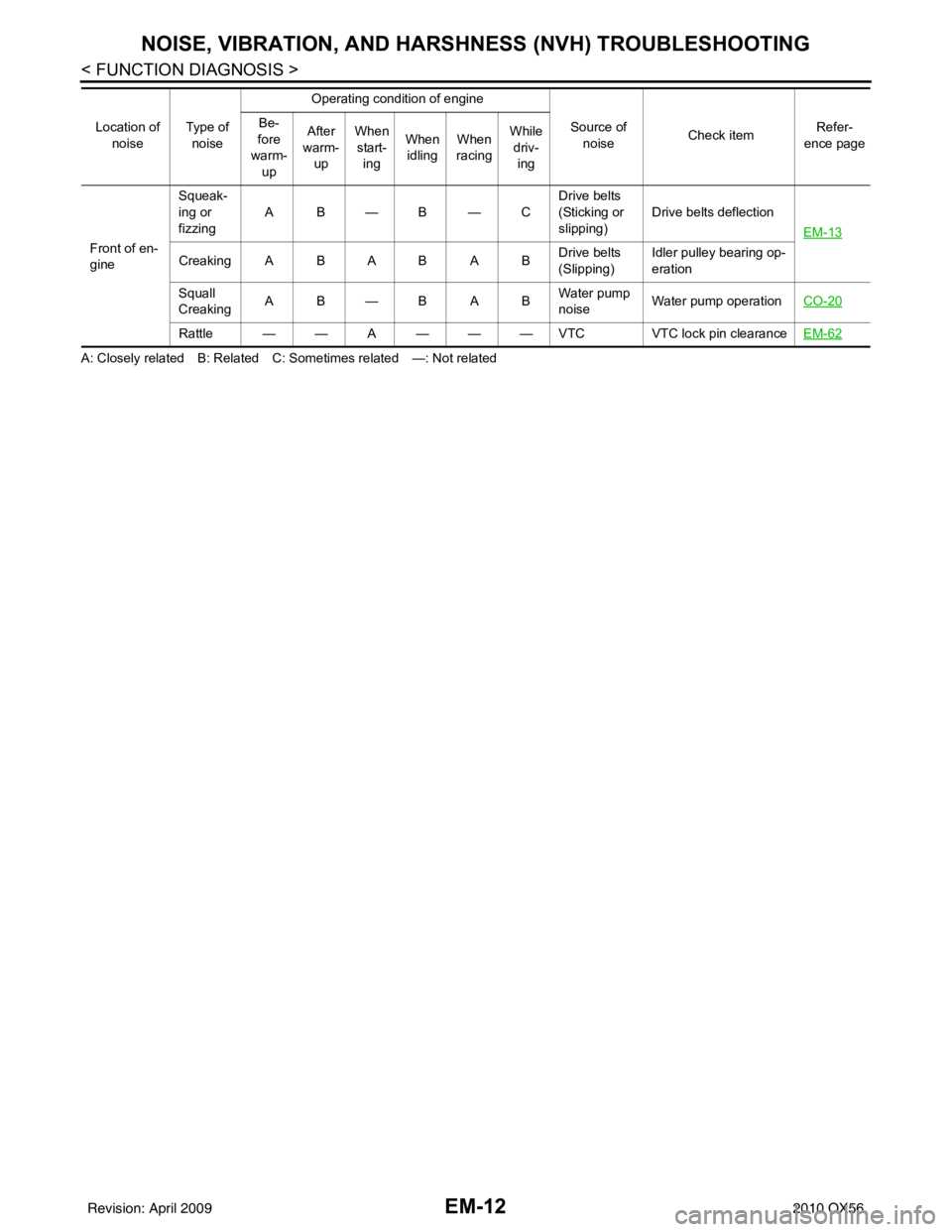
A: Closely related B: Related C: Sometimes related —: Not relatedFront of en-
gine
Squeak-
ing or
fizzing
AB—B—C
Drive belts
(Sticking or
slipping)Drive belts deflection
EM-13
Creaking A B A B A B Drive belts
(Slipping)Idler pulley bearing op-
eration
Squall
Creaking AB—BAB Water pump
noiseWater pump operation
CO-20
Rattle — — A — — — VTC VTC lock pin clearanceEM-62
Location of
noise Type of
noise Operating condition of engine
Source of noise Check item Refer-
ence page
Be-
fore
warm- up After
warm- up When
start- ing When
idling When
racing While
driv- ing
Revision: April 20092010 QX56
Page 1864 of 4210
DRIVE BELTSEM-13
< ON-VEHICLE MAINTENANCE >
C
DE
F
G H
I
J
K L
M A
EM
NP
O
ON-VEHICLE MAINTENANCE
DRIVE BELTS
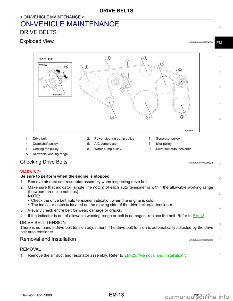
Exploded ViewINFOID:0000000005148974
Checking Drive BeltsINFOID:0000000005148975
WARNING:
Be sure to perform when the engine is stopped.
1. Remove air duct and resonator assembly when inspecting drive belt.
2. Make sure that indicator (single line notch) of eac
h auto tensioner is within the allowable working range
(between three line notches).
NOTE:
• Check the drive belt auto tensioner indication when the engine is cold.
• The indicator notch is located on the moving side of the drive belt auto tensioner.
3. Visually check entire belt for wear, damage or cracks.
4. If the indicator is out of allowable working range or belt is damaged, replace the belt. Refer to EM-13
.
DRIVE BELT TENSION
There is no manual drive belt tension adjustment. The driv e belt tension is automatically adjusted by the drive
belt auto tensioner.
Removal and InstallationINFOID:0000000005148976
REMOVAL
1. Remove the air duct and resonator assembly. Refer to EM-25, "Removal and Installation".
1. Drive belt2. Power steering pump pulley 3. Generator pulley
4. Crankshaft pulley 5. A/C compressor6. Idler pulley
7. Cooling fan pulley 8. Water pump pulley9. Drive belt auto tensioner
A. Allowable working range
LBIA0391E
Revision: April 20092010 QX56
Page 1865 of 4210
EM-14
< ON-VEHICLE MAINTENANCE >
DRIVE BELTS
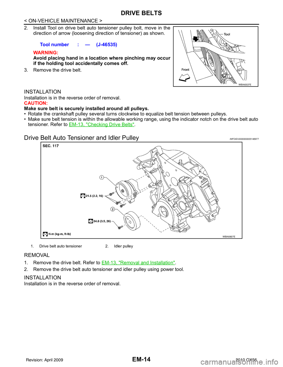
2. Install Tool on drive belt auto tensioner pulley bolt, move in thedirection of arrow (loosening direction of tensioner) as shown.
WARNING:
Avoid placing hand in a locatio n where pinching may occur
if the holding tool accidentally comes off.
3. Remove the drive belt.
INSTALLATION
Installation is in the reverse order of removal.
CAUTION:
Make sure belt is securely installed around all pulleys.
• Rotate the crankshaft pulley several turns clockwise to equalize belt tension between pulleys.
• Make sure belt tension is within the allowable working range, using the indicator notch on the drive belt auto tensioner. Refer to EM-13, "
Checking Drive Belts".
Drive Belt Auto Tensioner and Idler PulleyINFOID:0000000005148977
REMOVAL
1. Remove the drive belt. Refer to EM-13, "Removal and Installation".
2. Remove the drive belt auto tensioner and idler pulley using power tool.
INSTALLATION
Installation is in the reverse order of removal. Tool number : — (J-46535)
WBIA0537E
WBIA0607E
1. Drive belt auto tensioner
2. Idler pulley
Revision: April 20092010 QX56