Page 3194 of 4210
REAR SUSPENSION ASSEMBLYRSU-7
< ON-VEHICLE MAINTENANCE >
C
DF
G H
I
J
K L
M A
B
RSU
N
O P
• If vehicle height is not within ± 10 mm (0.39 in) of the specification, perform the control unit initialization
procedure. Refer to RSU-26, "
Initialization Procedure" .
GENERAL INFORMATION AND RECOMMENDATIONS
1. A Four-Wheel Thrust Alignment should be performed.
• This type of alignment is re commended for any NISSAN vehicle.
• The four-wheel “thrust” process helps ensure that the vehicle is properly aligned and the steering wheel
is centered.
• The alignment machine itself should be ca pable of accepting any NISSAN vehicle.
• The alignment machine should be checked to ensure that it is level.
2. Make sure the alignment machine is properly calibrated. • Your alignment machine should be regularly calibrated in order to give correct information.
• Check with the manufacturer of your specific a lignment machine for their recommended Service/Cali-
bration Schedule.
THE ALIGNMENT PROCESS
IMPORTANT: Use only the alignment specifications listed in this Service Manual. Refer to RSU-29, "Wheel
Alignment" .
1. When displaying the alignment settings, many alignm ent machines use “indicators”: (Green/red, plus or
minus, Go/No Go). Do NOT use these indicators.
• The alignment specifications programmed into your alignment machine that operate these indicators
may not be correct.
• This may result in an ERROR.
2. Some newer alignment machines are equipped with an optional “Rolling Compensation” method to “com-
pensate” the sensors (alignment targets or head units). Do NOT use this “Rolling Compensation”
method.
• Use the “Jacking Compensation” method. After installing the alignment targets or head units, raise the vehicle and rotate the wheels 1/2 turn both ways.
• See Instructions in the alignment machine you are using for more information.
CAMBER
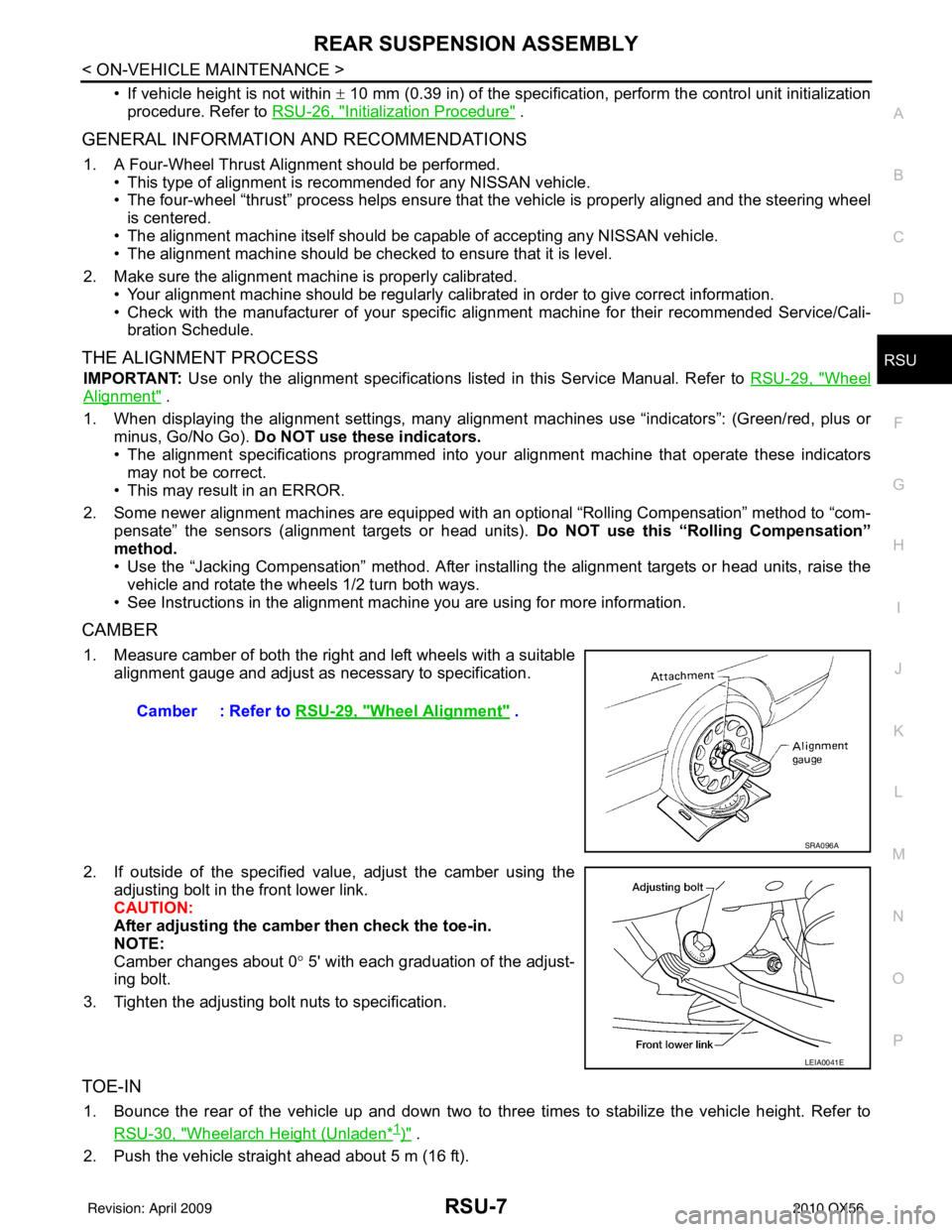
1. Measure camber of both the right and left wheels with a suitable alignment gauge and adjust as necessary to specification.
2. If outside of the specified value, adjust the camber using the adjusting bolt in the front lower link.
CAUTION:
After adjusting the camber then check the toe-in.
NOTE:
Camber changes about 0 ° 5' with each graduation of the adjust-
ing bolt.
3. Tighten the adjusting bolt nuts to specification.
TOE-IN
1. Bounce the rear of the vehicle up and down two to three times to stabilize the vehicle height. Refer to RSU-30, "
Wheelarch Height (Unladen*1)" .
2. Push the vehicle straight ahead about 5 m (16 ft). Camber : Refer to
RSU-29, "
Wheel Alignment" .
SRA096A
LEIA0041E
Revision: April 20092010 QX56
Page 3197 of 4210
RSU-10
< ON-VEHICLE REPAIR >
REAR SUSPENSION ASSEMBLY
Rear Load Leveling Air Suspension System
13. Coil spring14. Upper rubber seat15. Rear suspension member
16. Spare tire bracket 17. Bound bumper Front
AWEIA0054GB
1. Rear load leveling air suspension
hose, RH 2. Shock absorber, RH
3. Height sensor
4. Rear load leveling air suspension hose, LH 5. Shock absorber, LH
6. Rear load leveling air suspension
compressor assembly
Front
Revision: April 20092010 QX56
Page 3199 of 4210
RSU-12
< REMOVAL AND INSTALLATION >
REAR SUSPENSION MEMBER
Rear Load Leveling Air Suspension System
REMOVAL
1. Use the CONSULT-III “EXHAUST SOLENOID” active test to release the air pressure from the rear load
leveling air suspension system.
2. Disconnect the electrical connectors for the height sensor and the rear load leveling air suspension com-
pressor assembly.
3. Unclip the rubber cover to access the rear load leveling air suspension compressor assembly.
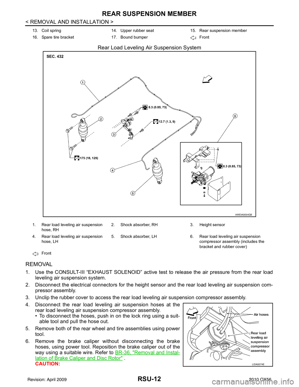
4. Disconnect the rear load leveling air suspension hoses at the rear load leveling air suspension compressor assembly.
• To disconnect the hoses, push in on the lock ring using a suit-able tool and pull the hose out.
5. Remove both of the rear wheel and tire assemblies using power tool.
6. Remove the brake caliper without disconnecting the brake hoses, using power tool. Reposition the brake caliper out of the
way using a suitable wire. Refer to BR-36, "
Removal and Instal-
lation of Brake Caliper and Disc Rotor" .
CAUTION:
13. Coil spring 14. Upper rubber seat15. Rear suspension member
16. Spare tire bracket 17. Bound bumper Front
AWEIA0054GB
1. Rear load leveling air suspension
hose, RH 2. Shock absorber, RH
3. Height sensor
4. Rear load leveling air suspension hose, LH 5. Shock absorber, LH
6. Rear load leveling air suspension
compressor assembly (includes the
bracket and rubber cover)
Front
LEIA0074E
Revision: April 20092010 QX56
Page 3200 of 4210
REAR SUSPENSION MEMBERRSU-13
< REMOVAL AND INSTALLATION >
C
DF
G H
I
J
K L
M A
B
RSU
N
O P
• Do not crimp or stretch the brake hose when re positioning the brake caliper out of the way.
• Do not press brake pedal while the brake caliper is removed.
7. Remove the spare tire.
8. Disconnect the two rear ABS sensor electrical connectors.
9. Remove the two rear drive shafts. Refer to RAX-10, "
Removal and Installation" .
10. Remove the rear final drive. Refer to DLN-250, "
Removal and Installation" .
11. Remove the EVAP canister bolt from the top of the rear suspension member.
12. Disconnect the parking brake cables from the brackets on the rear suspension member.
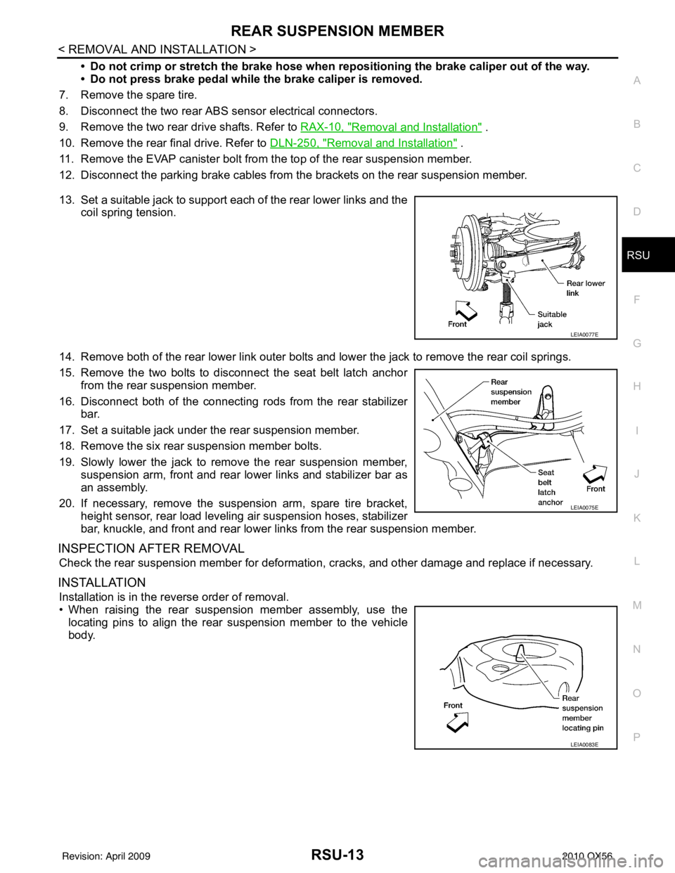
13. Set a suitable jack to support each of the rear lower links and the coil spring tension.
14. Remove both of the rear lower link outer bolts and lower the jack to remove the rear coil springs.
15. Remove the two bolts to disconnect the seat belt latch anchor from the rear suspension member.
16. Disconnect both of the connecting rods from the rear stabilizer
bar.
17. Set a suitable jack under the rear suspension member.
18. Remove the six rear suspension member bolts.
19. Slowly lower the jack to remove the rear suspension member, suspension arm, front and rear lower links and stabilizer bar as
an assembly.
20. If necessary, remove the suspension arm, spare tire bracket, height sensor, rear load leveling air suspension hoses, stabilizer
bar, knuckle, and front and rear lower links from the rear suspension member.
INSPECTION AFTER REMOVAL
Check the rear suspension member for deformation, cracks, and other damage and replace if necessary.
INSTALLATION
Installation is in the reverse order of removal.
• When raising the rear suspension member assembly, use the
locating pins to align the rear suspension member to the vehicle
body.
LEIA0077E
LEIA0075E
LEIA0083E
Revision: April 20092010 QX56
Page 3208 of 4210
REAR LOWER LINK & COIL SPRINGRSU-21
< REMOVAL AND INSTALLATION >
C
DF
G H
I
J
K L
M A
B
RSU
N
O P
REAR LOWER LINK & COIL SPRING
Removal and InstallationINFOID:0000000005148136
REMOVAL
1. Remove the wheel and tire assembly using power tool. Refer to WT-49, "Rotation" .
2. Use CONSULT-III "EXHAUST SOLENOID" active test to release the air pressure from the rear load level-
ing air suspension system.
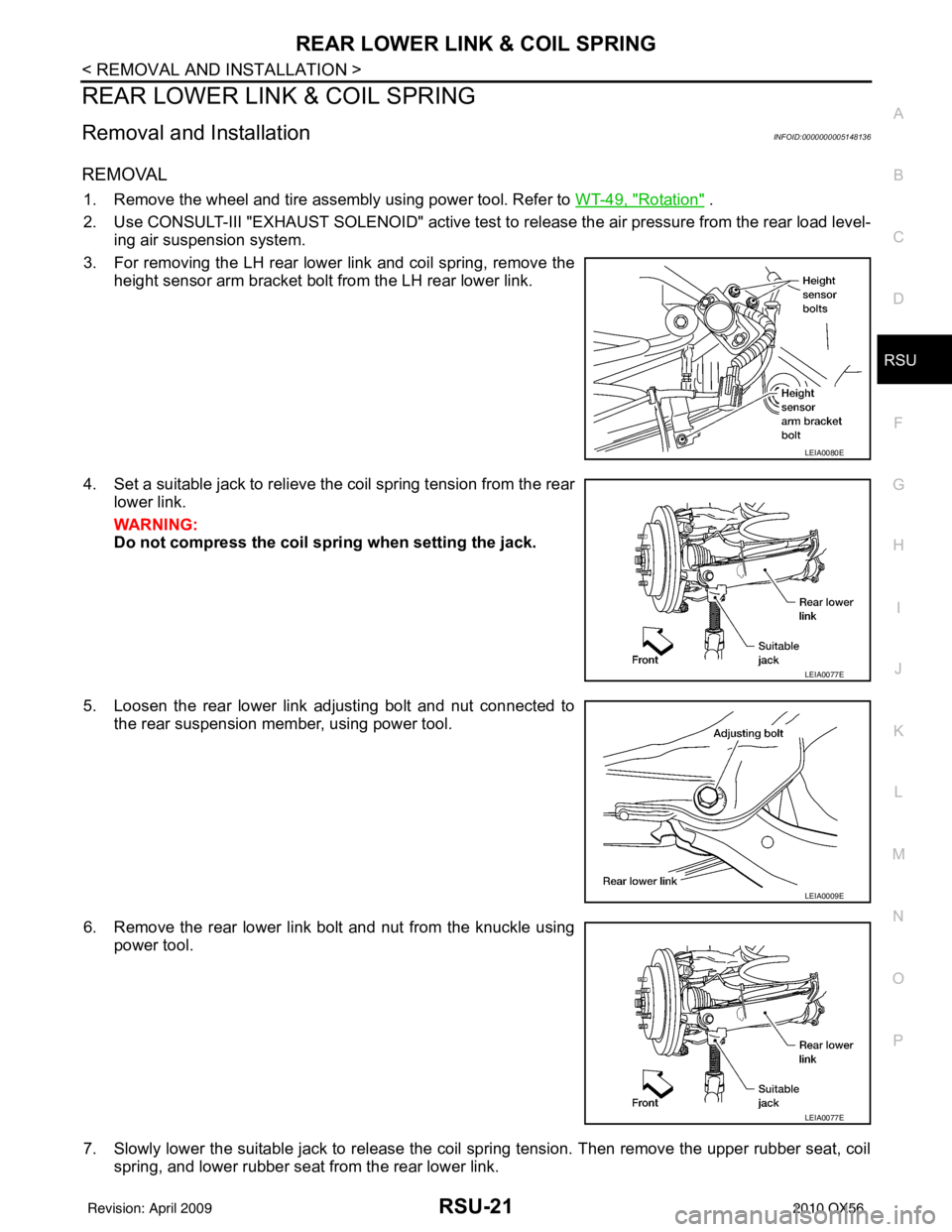
3. For removing the LH rear lower link and coil spring, remove the height sensor arm bracket bolt from the LH rear lower link.
4. Set a suitable jack to relieve the coil spring tension from the rear lower link.
WARNING:
Do not compress the coil sp ring when setting the jack.
5. Loosen the rear lower link adjusting bolt and nut connected to the rear suspension member, using power tool.
6. Remove the rear lower link bolt and nut from the knuckle using power tool.
7. Slowly lower the suitable jack to release the coil spring tension. Then remove the upper rubber seat, coil spring, and lower rubber seat from the rear lower link.
LEIA0080E
LEIA0077E
LEIA0009E
LEIA0077E
Revision: April 20092010 QX56
Page 3211 of 4210
RSU-24
< REMOVAL AND INSTALLATION >
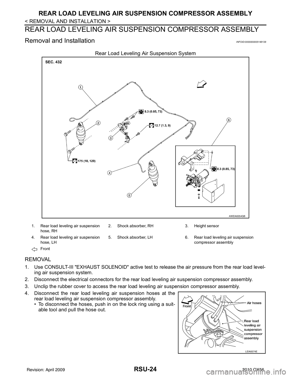
REAR LOAD LEVELING AIR SUSPENSION COMPRESSOR ASSEMBLY
REAR LOAD LEVELING AIR SUSPENSION COMPRESSOR ASSEMBLY
Removal and InstallationINFOID:0000000005148138
Rear Load Leveling Air Suspension System
REMOVAL
1. Use CONSULT-III "EXHAUST SOLENOID" active test to release the air pressure from the rear load level-
ing air suspension system.
2. Disconnect the electrical connectors for the rear load leveling air suspension compressor assembly.
3. Unclip the rubber cover to access the rear load leveling air suspension compressor assembly.
4. Disconnect the rear load leveling air suspension hoses at the rear load leveling air suspension compressor assembly.
• To disconnect the hoses, push in on the lock ring using a suit-
able tool and pull the hose out.
AWEIA0054GB
1. Rear load leveling air suspension
hose, RH 2. Shock absorber, RH
3. Height sensor
4. Rear load leveling air suspension hose, LH 5. Shock absorber, LH
6. Rear load leveling air suspension
compressor assembly
Front
LEIA0074E
Revision: April 20092010 QX56
Page 3214 of 4210
HEIGHT SENSORRSU-27
< REMOVAL AND INSTALLATION >
C
DF
G H
I
J
K L
M A
B
RSU
N
O P
HEIGHT SENSOR
Removal and InstallationINFOID:0000000005148141
Rear Load Leveling Air Suspension System
REMOVAL
1. Use CONSULT-III “EXHAUST SOLENOID ” active test to release the air pressure from the rear load level-
ing air suspension system.
2. Disconnect the electrical connector for the height sensor.
3. Remove the two height sensor bolts and height sensor arm bracket bolt.
4. Remove the height sensor.
INSTALLATION
Installation is in the reverse order of removal.
AWEIA0054GB
1. Rear load leveling air suspension hose, RH 2. Shock absorber, RH 3. Height sensor
4. Rear load leveling air suspension hose, LH 5. Shock absorber, LH
6. Rear load leveling air suspension
compressor assembly
Front
LEIA0080E
Revision: April 20092010 QX56
Page 3215 of 4210
RSU-28
< REMOVAL AND INSTALLATION >
HEIGHT SENSOR
1. Start the engine.
2. Use CONSULT-III to perform "STANDARD HEIGHT LEVEL" work support function.
3. Using data monitor of CONSULT-III, verify "HEIGT CALC" is at 0 mm.
4. Check the vehicle height. Refer to RSU-30, "
Wheelarch Height (Unladen*1)" . If vehicle height is not within
± 10 mm (0 ± 0.39 in) of the specification, perform the initialization procedure. Refer to RSU-26, "
Initializa-
tion Procedure".
Revision: April 20092010 QX56