Page 2293 of 4210

HA-1
VENTILATION, HEATER & AIR CONDITIONER
C
DE
F
G H
J
K L
M
SECTION HA
A
B
HA
N
O P
CONTENTS
HEATER & AIR CONDITIONING SYSTEM
PRECAUTION ....... ........................................3
PRECAUTIONS .............................................. .....3
Precaution for Supplemental Restraint System
(SRS) "AIR BAG" and "SEAT BELT PRE-TEN-
SIONER" ............................................................. ......
3
Precaution Necessary for Steering Wheel Rota-
tion After Battery Disconnect ............................... ......
3
Precaution for Working with HFC-134a (R-134a) ......4
Precaution for Procedure without Cowl Top Cover ......4
Contaminated Refrigerant .........................................4
General Refrigerant Precaution ................................5
Precaution for Leak Detection Dye ...........................5
A/C Identification Label .............................................5
Precaution for Refrigerant Connection ......................5
Precaution for Service of Compressor ................ ....10
Precaution for Service Equipment ....................... ....10
PREPARATION ...........................................13
PREPARATION .............................................. ....13
Special Service Tool ........................................... ....13
HFC-134a (R-134a) Service Tool and Equipment ....13
Commercial Service Tool ........................................16
FUNCTION DIAGNOSIS ..............................17
REFRIGERATION SYSTEM .......................... ....17
Refrigerant Cycle ................................................ ....17
Refrigerant System Protection ................................17
OIL .................................................................. ....19
Maintenance of Oil in Compressor ...................... ....19
ON-VEHICLE MAINTENANCE ....................20
REFRIGERATION SYSTEM .......................... ....20
HFC-134a (R-134a) Service Procedure ..................20
OIL .................................................................. ....22
Maintenance of Oil Quantity in Compressor ....... ....22
FLUORESCENT LEAK DETECTOR ................24
Checking of Refrigerant Leaks ................................24
Checking System for Leaks Using the Fluorescent
Dye Leak Detector ............................................... ....
24
Dye Injection ............................................................24
ELECTRICAL LEAK DETECTOR ....................26
Checking of Refrigerant Leaks ................................26
Electronic Refrigerant Leak Detector ................... ....26
ON-VEHICLE REPAIR .................................29
REFRIGERATION SYSTEM .............................29
Component .......................................................... ....29
COMPRESSOR .................................................31
Removal and Installation for Compressor ...............31
Removal and Installation for Compressor Clutch ....32
LOW-PRESSURE FLEXIBLE HOSE ................36
Removal and Installation for Low-Pressure Flexi-
ble Hose .............................................................. ....
36
LOW-PRESSURE PIPE ....................................37
Removal and Installation for Low-Pressure Pipe .....37
Removal and Installation for Rear High- and Low-
Pressure A/C and Heater Core Pipes ......................
37
Removal and Installation for Underfloor Rear
High- and Low-Pressure A/C and Heater Core
Pipes ........................................................................
38
HIGH-PRESSURE FLEXIBLE HOSE ...............40
Removal and Installation for High-Pressure Flexi-
ble Hose ..................................................................
40
HIGH-PRESSURE PIPE ....................................41
Removal and Installation for High-Pressure Pipe ....41
Removal and Installation for Rear High- and Low-
Pressure A/C and Heater Core Pipes .................. ....
41
Removal and Installation for Underfloor Rear
High- and Low-Pressure A/C and Heater Core
Pipes ........................................................................
42
Revision: April 20092010 QX56
Page 2302 of 4210

HA-10
< PRECAUTION >
PRECAUTIONS
Precaution for Service of Compressor
INFOID:0000000005147637
• Plug all openings to prevent moisture and foreign matter from entering.
• When the compressor is removed, store it in th e same position as it is when mounted on the car.
• When replacing or repairing compressor, follow “Maintenance of Oil Quantity in Compressor”
exactly. Refer to HA-22, "
Maintenance of Oil Quantity in Compressor".
• Keep friction surfaces between clut ch and pulley clean. If the surface is contaminated with oil, wipe
it off by using a clean waste cloth moistened with thinner.
• After compressor service operation, turn the compressor shaft by ha nd more than 5 turns in both
directions. This will equally distribute oil inside the compressor. After the compressor is installed,
let the engine idle and oper ate the compressor for 1 hour.
• After replacing the compressor magnet clutch, apply voltage to the new one and check for normal
operation. Refer to HA-32, "
Removal and Installation for Compressor Clutch".
Precaution for Service EquipmentINFOID:0000000005147638
RECOVERY/RECYCLING EQUIPMENT
Follow the manufacturer's instructions for machi ne operation and machine maintenance. Never introduce any
refrigerant other than that specified into the machine.
ELECTRONIC LEAK DETECTOR
Follow the manufacturer's instructions for tester operation and tester maintenance.
VACUUM PUMP
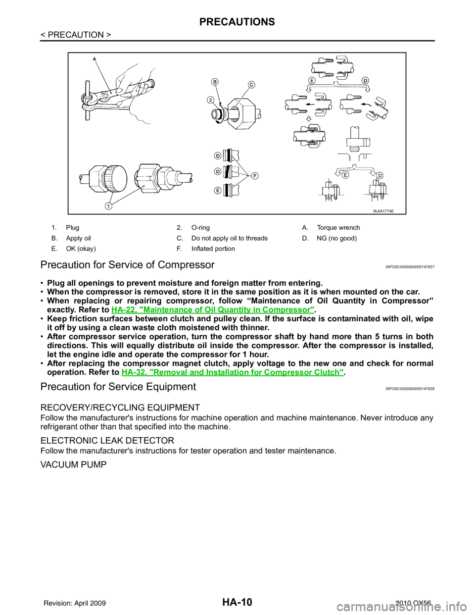
1. Plug 2. O-ring A. Torque wrench
B. Apply oil C. Do not apply oil to threads D. NG (no good)
E. OK (okay) F. Inflated portion
WJIA1774E
Revision: April 20092010 QX56
Page 2305 of 4210

PREPARATIONHA-13
< PREPARATION >
C
DE
F
G H
J
K L
M A
B
HA
N
O P
PREPARATION
PREPARATION
Special Service ToolINFOID:0000000005147639
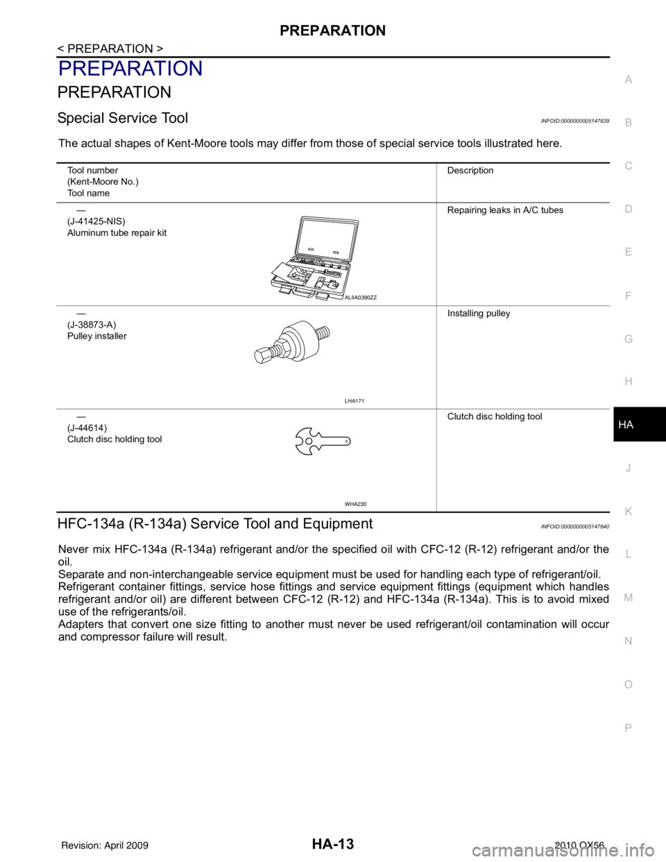
The actual shapes of Kent-Moore tools may differ from those of special service tools illustrated here.
HFC-134a (R-134a) Service Tool and EquipmentINFOID:0000000005147640
Never mix HFC-134a (R-134a) refrigerant and/or the specified oil with CFC-12 (R-12) refrigerant and/or the
oil.
Separate and non-interchangeable service equipment must be used for handling each type of refrigerant/oil.
Refrigerant container fittings, service hose fittings and service equipment fittings (equipment which handles
refrigerant and/or oil) are different between CFC-12 (R-12) and HFC-134a (R-134a). This is to avoid mixed
use of the refrigerants/oil.
Adapters that convert one size fitting to another must never be used refrigerant/oil contamination will occur
and compressor failure will result.
Tool number
(Kent-Moore No.)
Tool name Description
—
(J-41425-NIS)
Aluminum tube repair kit Repairing leaks in A/C tubes
—
(J-38873-A)
Pulley installer Installing pulley
—
(J-44614)
Clutch disc holding tool Clutch disc holding tool
ALIIA0390ZZ
LHA171
WHA230
Revision: April 20092010 QX56
Page 2309 of 4210

REFRIGERATION SYSTEMHA-17
< FUNCTION DIAGNOSIS >
C
DE
F
G H
J
K L
M A
B
HA
N
O P
FUNCTION DIAGNOSIS
REFRIGERATION SYSTEM
Refrigerant CycleINFOID:0000000005147642
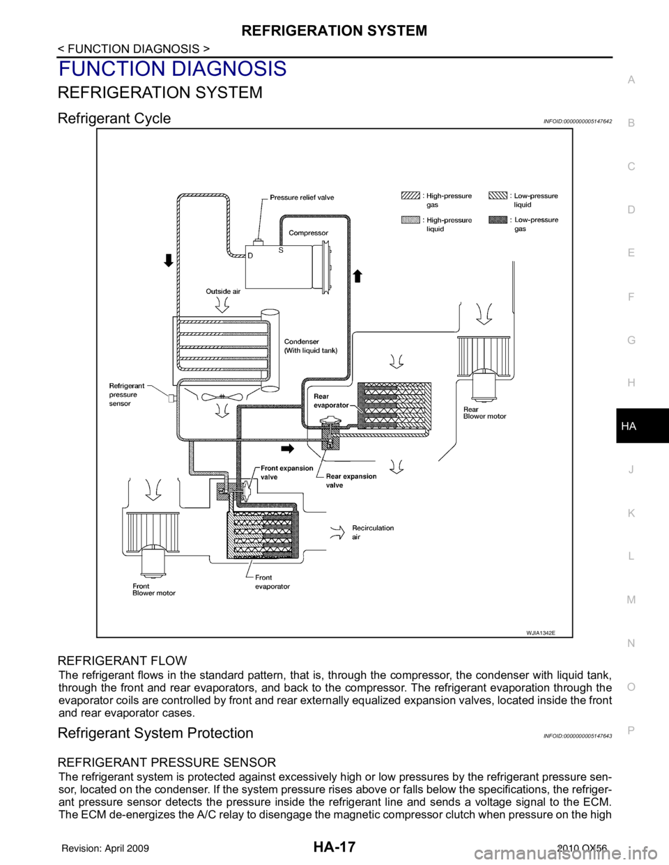
REFRIGERANT FLOW
The refrigerant flows in the standard pattern, that is, through the compressor, the condenser with liquid tank,
through the front and rear evaporators, and back to the compressor. The refrigerant evaporation through the
evaporator coils are controlled by front and rear externally equalized expansion valves, located inside the front
and rear evaporator cases.
Refrigerant System ProtectionINFOID:0000000005147643
REFRIGERANT PRESSURE SENSOR
The refrigerant system is protected against excessively hi gh or low pressures by the refrigerant pressure sen-
sor, located on the condenser. If the system pressure rises above or falls below the specifications, the refriger-
ant pressure sensor detects the pressure inside the refrigerant line and sends a voltage signal to the ECM.
The ECM de-energizes the A/C relay to disengage the magnetic compressor clutch when pressure on the high
WJIA1342E
Revision: April 20092010 QX56
Page 2324 of 4210
HA-32
< ON-VEHICLE REPAIR >
COMPRESSOR
• After recharging the A/C system with refrigerant, check for leaks.
Removal and Installation for Compressor ClutchINFOID:0000000005147654
Magnet Clutch Assembly
REMOVAL
1. Remove the compressor. Refer to HA-31, "Removal and Installation for Compressor".
2. Remove the center bolt while holding the clutch disc stationary using Tool as shown.
3. Remove the clutch disc and shims. CAUTION:
Retain all of the shims for installation.
4. Remove the snap ring using a suitable tool.
AWIIA1286GB
1. Magnet clutch assembly 2. Magnet coil 3. Pulley
4. Clutch disc 5. Snap ring 6. Thermal protector (built in)
7. Compressor
Tool number : — (J-44614)
WHA228
RHA072C
Revision: April 20092010 QX56
Page 2325 of 4210

COMPRESSORHA-33
< ON-VEHICLE REPAIR >
C
DE
F
G H
J
K L
M A
B
HA
N
O P
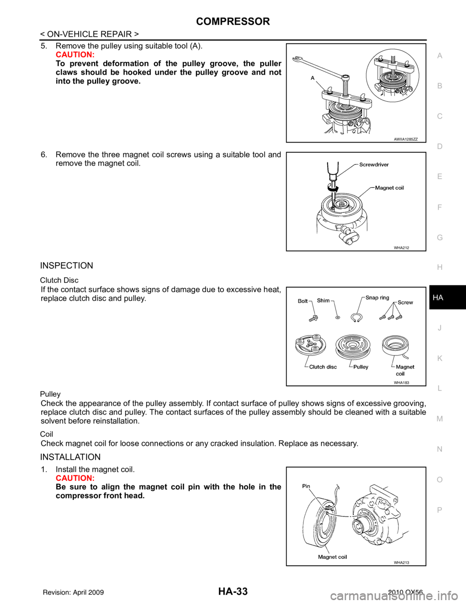
5. Remove the pulley using suitable tool (A). CAUTION:
To prevent deformation of the pulley groove, the puller
claws should be hooked un der the pulley groove and not
into the pulley groove.
6. Remove the three magnet coil screws using a suitable tool and remove the magnet coil.
INSPECTION
Clutch Disc
If the contact surface shows signs of damage due to excessive heat,
replace clutch disc and pulley.
Pulley
Check the appearance of the pulley assembly. If contact surface of pulley shows signs of excessive grooving,
replace clutch disc and pulley. The contact surfaces of the pulley assembly should be cleaned with a suitable
solvent before reinstallation.
Coil
Check magnet coil for loose connections or any cracked insulation. Replace as necessary.
INSTALLATION
1. Install the magnet coil. CAUTION:
Be sure to align the magnet coil pin with the hole in the
compressor front head.
AWIIA1285ZZ
WHA212
WHA183
WHA213
Revision: April 20092010 QX56
Page 2326 of 4210
HA-34
< ON-VEHICLE REPAIR >
COMPRESSOR
2. Install the pulley assembly using Tool and a wrench, then installthe snap ring using a suitable tool.
3. Install the clutch disc on the compressor shaft, together with all the original shim(s) using a suitabl e tool. Press the clutch disc in
by hand.
4. Install the clutch pulley bolt while using Tool to prevent the clutch
disc from turning and tighten the bolt to specification.
CAUTION:
After tightening the clutch pu lley bolt, check that the clutch
pulley rotates smoothly.
5. Check the pulley clearance all the way around the clutch disc as shown.
6. If the specified clearance is not obtained, replace the adjusting spacer to readjust.
7. Install the compressor. Refer to HA-31, "
Removal and Installa-
tion for Compressor".
Tool number : — (J-38873-A)
WJIA1016E
WHA184
Tool number : — (J-44614)
WHA229
Clutch disc-to-pulley clearance : 0.3 - 0.6 mm
(0.012 - 0.024 in)
WHA194
Revision: April 20092010 QX56
Page 2327 of 4210
COMPRESSORHA-35
< ON-VEHICLE REPAIR >
C
DE
F
G H
J
K L
M A
B
HA
N
O P
BREAK-IN OPERATION
When replacing compressor clutch assembly, always conduct the break-in operation. This is done by engag-
ing and disengaging the clutch about 30 times. Break-in operation raises the level of transmitted torque.
Revision: April 20092010 QX56