2010 INFINITI QX56 keyless entry
[x] Cancel search: keyless entryPage 2475 of 4210
INL-6
< FUNCTION DIAGNOSIS >
INTERIOR ROOM LAMP CONTROL SYSTEM
FUNCTION DIAGNOSIS
INTERIOR ROOM LAMP CONTROL SYSTEM
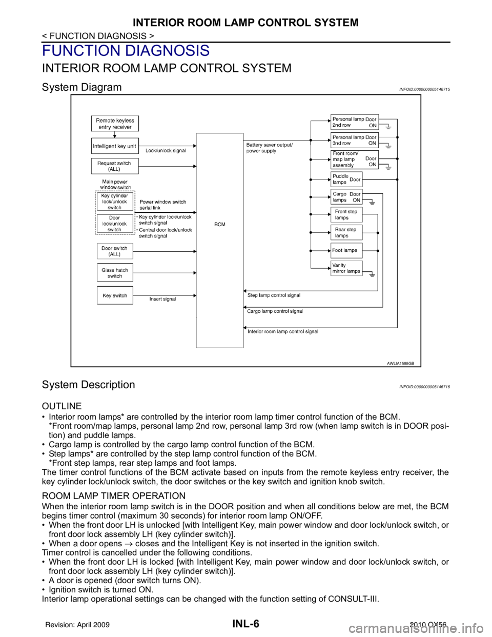
System DiagramINFOID:0000000005146715
System DescriptionINFOID:0000000005146716
OUTLINE
• Interior room lamps* are controlled by the interior room lamp timer control function of the BCM.
*Front room/map lamps, personal lamp 2nd row, personal lamp 3rd row (when lamp switch is in DOOR posi-
tion) and puddle lamps.
• Cargo lamp is controlled by the cargo lamp control function of the BCM.
• Step lamps* are controlled by the step lamp control function of the BCM. *Front step lamps, rear step lamps and foot lamps.
The timer control functions of the BCM activate based on inputs from the remote keyless entry receiver, the
key cylinder lock/unlock switch, the door switc hes or the key switch and ignition knob switch.
ROOM LAMP TIMER OPERATION
When the interior room lamp switch is in the DOOR position and when all conditions below are met, the BCM
begins timer control (maximum 30 seconds) for interior room lamp ON/OFF.
• When the front door LH is unlocked [with Intelligent Key, main power window and door lock/unlock switch, or
front door lock assembly LH (key cylinder switch)].
• When a door opens → closes and the Intelligent Key is not inserted in the ignition switch.
Timer control is cancelled under the following conditions.
• When the front door LH is locked [with Intelligent Key, main power window and door lock/unlock switch, or
front door lock assembly LH (key cylinder switch)].
• A door is opened (door switch turns ON).
• Ignition switch is turned ON.
Interior lamp operational settings can be c hanged with the function setting of CONSULT-III.
AWLIA1595GB
Revision: April 20092010 QX56
Page 2480 of 4210

DIAGNOSIS SYSTEM (BCM)INL-11
< FUNCTION DIAGNOSIS >
C
DE
F
G H
I
J
K
M A
B
INL
N
O P
DIAGNOSIS SYSTEM (BCM)
COMMON ITEM
COMMON ITEM : CONSULT-III Fu nction (BCM - COMMON ITEM)INFOID:0000000005356686
APPLICATION ITEM
CONSULT-III performs the following functions via CAN communication with BCM.
SYSTEM APPLICATION
BCM can perform the following functions for each system.
NOTE:
It can perform the diagnosis modes except the following for all sub system selection items.
INT LAMP
Diagnosis mode Function Description
WORK SUPPORT Changes the setting for each system function.
SELF-DIAG RESULTS Displays the diagnosis results judged by BCM. Refer to BCS-54, "
DTCIndex".
CAN DIAG SUPPORT MNTR Monitors the reception status of CAN communication viewed from BCM.
DATA MONITOR The BCM input/output signals are displayed.
ACTIVE TEST The signals used to activate each device are forcibly supplied from BCM.
ECU IDENTIFICATION The BCM pa rt number is displayed.
CONFIGURATION • Enables to read and save the vehicle specification.
• Enables to write the vehicle specification when replacing BCM.
System
Sub system selection item Diagnosis mode
WORK SUPPORT DATA MONITOR ACTIVE TEST
BCM BCM ×
Door lock DOOR LOCK ×××
Rear window defogger REAR DEFOGGER ×
Warning chime BUZZER ××
Interior room lamp timer INT LAMP ×××
Remote keyless entry system MULTI REMOTE ENT ××
Exterior lamp HEAD LAMP ×××
Wiper and washer WIPER ×××
Turn signal and hazard warning lamps FLASHER ××
Air conditioner AIR CONDITONER ×
Intelligent Key system INTELLIGENT KEY ×
Combination switch COMB SW ×
Immobilizer IMMU ××
Interior room lamp battery saver BATTERY SAVER ×××
Back door open TRUNK ××
RAP (retained accessory power) RETAINED PWR ×××
Signal buffer system SIGNAL BUFFER ××
TPMS (tire pressure monitoring sys-
tem) AIR PRESSURE MONITOR
×××
Vehicle security system THEFT ALM ×××
Panic alarm system PANIC ALARM ×
Revision: April 20092010 QX56
Page 2531 of 4210
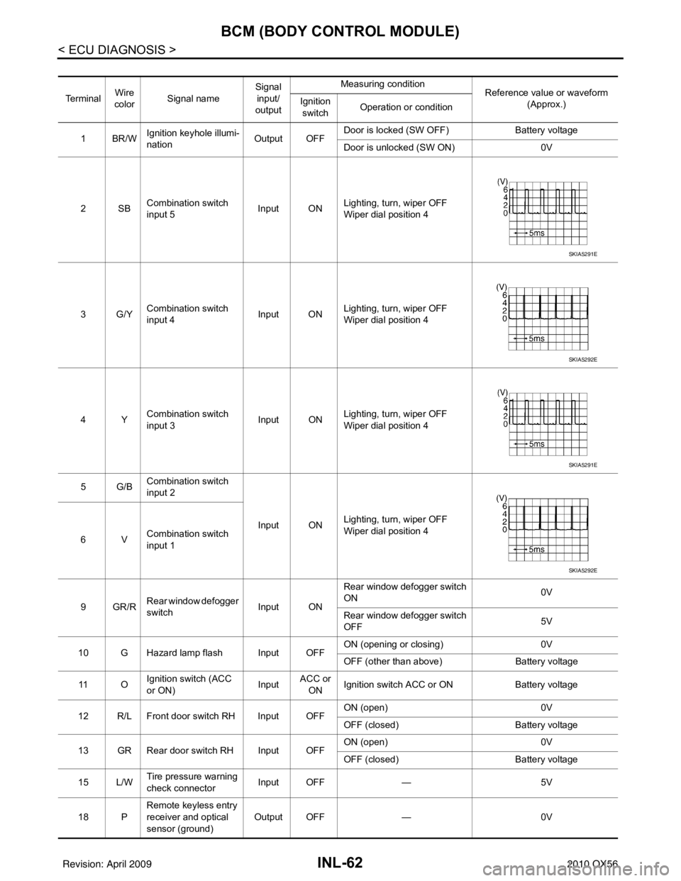
INL-62
< ECU DIAGNOSIS >
BCM (BODY CONTROL MODULE)
Te r m i n a lWire
color Signal name Signal
input/
output Measuring condition
Reference value or waveform
(Approx.)
Ignition
switch Operation or condition
1BR/W Ignition keyhole illumi-
nation Output OFFDoor is locked (SW OFF)
Battery voltage
Door is unlocked (SW ON) 0V
2SB Combination switch
input 5 Input ON
Lighting, turn, wiper OFF
Wiper dial position 4
3G/Y Combination switch
input 4 Input ONLighting, turn, wiper OFF
Wiper dial position 4
4Y Combination switch
input 3 Input ON
Lighting, turn, wiper OFF
Wiper dial position 4
5G/B Combination switch
input 2
Input ONLighting, turn, wiper OFF
Wiper dial position 4
6V Combination switch
input 1
9GR/R Rear window defogger
switch
Input ONRear window defogger switch
ON
0V
Rear window defogger switch
OFF 5V
10 G Hazard lamp flash Input OFF ON (opening or closing)
0V
OFF (other than above) Battery voltage
11 O Ignition switch (ACC
or ON)
InputACC or
ON Ignition switch ACC or ON
Battery voltage
12 R/L Front door switch RH Input OFF ON (open)
0V
OFF (closed) Battery voltage
13 GR Rear door switch RH Input OFF ON (open)
0V
OFF (closed) Battery voltage
15 L/W Tire pressure warning
check connector
Input OFF
—5V
18 P Remote keyless entry
receiver and optical
sensor (ground)
Output OFF
—0V
SKIA5291E
SKIA5292E
SKIA5291E
SKIA5292E
Revision: April 20092010 QX56
Page 2532 of 4210
BCM (BODY CONTROL MODULE)INL-63
< ECU DIAGNOSIS >
C
DE
F
G H
I
J
K
M A
B
INL
N
O P
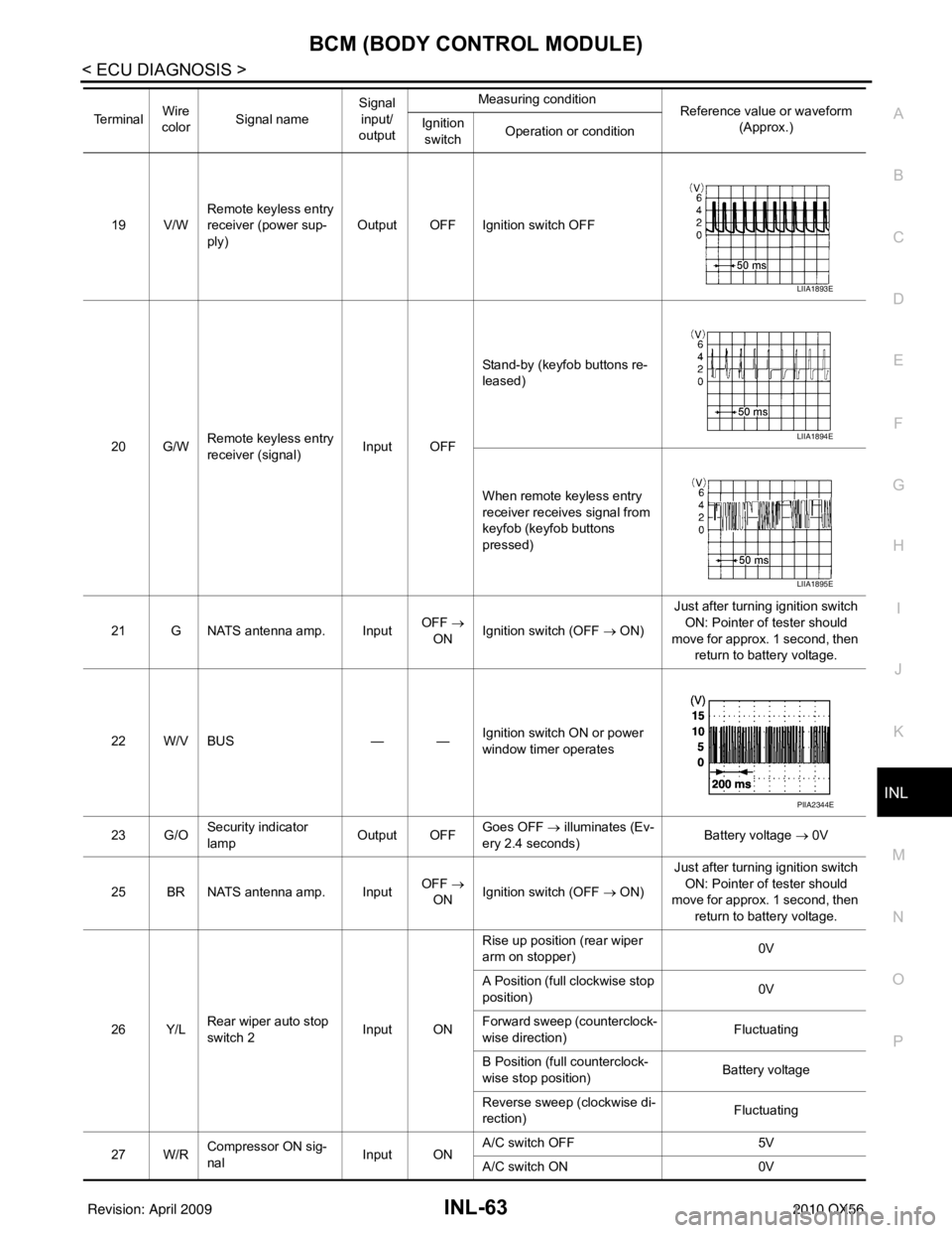
19 V/W Remote keyless entry
receiver (power sup-
ply) Output OFF Ignition switch OFF
20 G/W Remote keyless entry
receiver (signal) Input OFFStand-by (keyfob buttons re-
leased)
When remote keyless entry
receiver receives signal from
keyfob (keyfob buttons
pressed)
21 G NATS antenna amp. Input OFF
→
ON Ignition switch (OFF → ON) Just after turning ignition switch
ON: Pointer of tester should
move for approx. 1 second, then return to battery voltage.
22 W/V BUS — —Ignition switch ON or power
window timer operates
23 G/O Security indicator
lamp Output OFF
Goes OFF
→ illuminates (Ev-
ery 2.4 seconds) Battery voltage
→ 0V
25 BR NATS antenna amp. Input OFF
→
ON Ignition switch (OFF → ON) Just after turning ignition switch
ON: Pointer of tester should
move for approx. 1 second, then return to battery voltage.
26 Y/L Rear wiper auto stop
switch 2 Input ONRise up position (rear wiper
arm on stopper)
0V
A Position (full clockwise stop
position) 0V
Forward sweep (counterclock-
wise direction) Fluctuating
B Position (full counterclock-
wise stop position) Battery voltage
Reverse sweep (clockwise di-
rection) Fluctuating
27 W/R Compressor ON sig-
nal Input ONA/C switch OFF
5V
A/C switch ON 0V
Te r m i n a l
Wire
color Signal name Signal
input/
output Measuring condition
Reference value or waveform
(Approx.)
Ignition
switch Operation or condition
LIIA1893E
LIIA1894E
LIIA1895E
PIIA2344E
Revision: April 20092010 QX56
Page 2827 of 4210
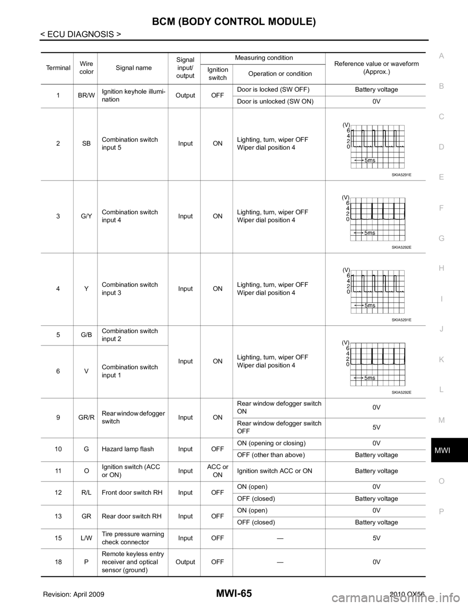
MWI
BCM (BODY CONTROL MODULE)MWI-65
< ECU DIAGNOSIS >
C
DE
F
G H
I
J
K L
M B A
O P
Te r m i n a l Wire
color Signal name Signal
input/
output Measuring condition
Reference value or waveform
(Approx.)
Ignition
switch Operation or condition
1BR/W Ignition keyhole illumi-
nation Output OFFDoor is locked (SW OFF)
Battery voltage
Door is unlocked (SW ON) 0V
2SB Combination switch
input 5 Input ON
Lighting, turn, wiper OFF
Wiper dial position 4
3G/Y Combination switch
input 4 Input ONLighting, turn, wiper OFF
Wiper dial position 4
4Y Combination switch
input 3 Input ON
Lighting, turn, wiper OFF
Wiper dial position 4
5G/B Combination switch
input 2
Input ONLighting, turn, wiper OFF
Wiper dial position 4
6V Combination switch
input 1
9GR/R Rear window defogger
switch
Input ONRear window defogger switch
ON
0V
Rear window defogger switch
OFF 5V
10 G Hazard lamp flash Input OFF ON (opening or closing)
0V
OFF (other than above) Battery voltage
11 O Ignition switch (ACC
or ON)
InputACC or
ON Ignition switch ACC or ON
Battery voltage
12 R/L Front door switch RH Input OFF ON (open)
0V
OFF (closed) Battery voltage
13 GR Rear door switch RH Input OFF ON (open)
0V
OFF (closed) Battery voltage
15 L/W Tire pressure warning
check connector
Input OFF
—5V
18 P Remote keyless entry
receiver and optical
sensor (ground)
Output OFF
—0V
SKIA5291E
SKIA5292E
SKIA5291E
SKIA5292E
Revision: April 20092010 QX56
Page 2828 of 4210
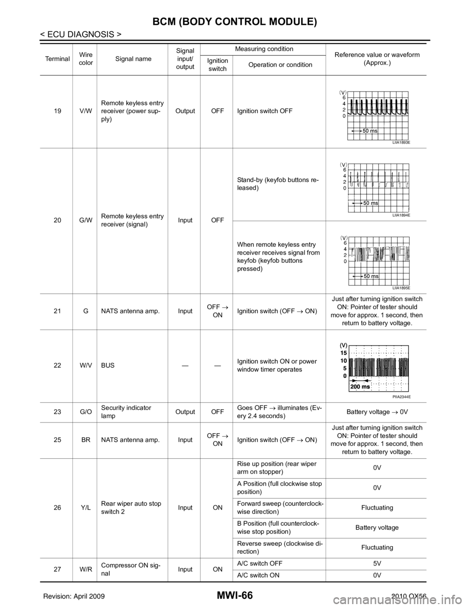
MWI-66
< ECU DIAGNOSIS >
BCM (BODY CONTROL MODULE)
19 V/WRemote keyless entry
receiver (power sup-
ply) Output OFF Ignition switch OFF
20 G/W Remote keyless entry
receiver (signal) Input OFFStand-by (keyfob buttons re-
leased)
When remote keyless entry
receiver receives signal from
keyfob (keyfob buttons
pressed)
21 G NATS antenna amp. Input OFF
→
ON Ignition switch (OFF
→ ON)Just after turning ignition switch
ON: Pointer of tester should
move for approx. 1 second, then return to battery voltage.
22 W/V BUS — —Ignition switch ON or power
window timer operates
23 G/O Security indicator
lamp Output OFF
Goes OFF
→ illuminates (Ev-
ery 2.4 seconds) Battery voltage
→ 0V
25 BR NATS antenna amp. Input OFF
→
ON Ignition switch (OFF
→ ON)Just after turning ignition switch
ON: Pointer of tester should
move for approx. 1 second, then return to battery voltage.
26 Y/L Rear wiper auto stop
switch 2 Input ONRise up position (rear wiper
arm on stopper)
0V
A Position (full clockwise stop
position) 0V
Forward sweep (counterclock-
wise direction) Fluctuating
B Position (full counterclock-
wise stop position) Battery voltage
Reverse sweep (clockwise di-
rection) Fluctuating
27 W/R Compressor ON sig-
nal Input ONA/C switch OFF
5V
A/C switch ON 0V
Te r m i n a l
Wire
color Signal name Signal
input/
output Measuring condition
Reference value or waveform
(Approx.)
Ignition
switch Operation or condition
LIIA1893E
LIIA1894E
LIIA1895E
PIIA2344E
Revision: April 20092010 QX56
Page 2953 of 4210

PG
HARNESSPG-43
< COMPONENT DIAGNOSIS >
C
DE
F
G H
I
J
K L
B A
O P
N
A3 M6 W/10 : To E10
G4 M84 W/16 : To B101
A2 M7 B/5 : Passenger select unlock relay B2 M85 W/3 : Tilt motor
A3 M8 W/16 : To D2 B2 M86 W/2 : Tilt motor
A2 M9 BR/24 : To D1 B3 M87 B/5 : Rear power vent window relay (open)
A3 M10 Y/4 : To E29 B3 M89 B/5 : Rear power vent window relay (close)
A3 M11 B/1 : Parking brake switch A3 M91 W/16 : To E26
C3 M12 GR/6 : Key switch and ignition knob switch A2 M92 GR/6 : Power liftgate switch
D3 M13 BR/2 : Front passenger air bag OFF indicator D1 M93 W/24 : Display unit
A1 M14 B/2 : Diode-3 A2 M95 W/6 : Rear power vent window switch
B3 M15 W/4 : Steering lock solenoid A2 M96 BR/6 : Pedal adjusting switch
A2 M16 GR/6 : ADP steering switch C2 M98 W/16 : A/C and AV switch assembly
B2 M17 W/8 : Steering angle sensor C3 M99 BR/2 : Foot lamp LH
C2 M18 W/40 : BCM (body control module) F4 M100 BR/2 : Foot lamp RH
C2 M19 W/15 : BCM (body control module) E3 M104 W/4 : Aux jack
C2 M20 B/15 : BCM (body control module) F2 M105 Y/2 : Front passenger air bag module
C3 M21 W/4 : NATS antenna AMP. F2 M106 O/2 : Front passenger air bag module
C3 M22 W/16 : Data link connector F3 M107 B/5 : Front blower relay
B1 M23 W/12 : Combination meter D5 M108 B/6 : Yaw rate/ side/ decel G sensor
C1 M24 W/40 : Combination meter A1 M109 BR/2 : Front tweeter LH
F2 M25 B/4 : Remote keyless entry receiver D2 M110 BR/2 : Center speaker
B2 M26 W/6 : Ignition switch F2 M111 BR/2 : Front tweeter RH
B2 M28 W/16 : Combination switch C2 M112 BR/14 : BOSE speaker amp.
B2 M29 Y/6 : Combination switch C2 M113 BR/23 : BOSE speaker amp.
B3 M30 GR/8 : Combination switch A2 M116 GR/8 : Sonar system OFF switch
G4 M31 SMJ : To E152 B1 M118 B/2 : Front sonar buzzer
C3 M32 W/4 : In-vehicle sensor F2 M120 W/4 : Remote keyless entry receiver
B3 M33 W/32 : Automatic drive positioner control unit F4 M122 W/4 : Variable blower control (front)
B3 M34 W/16 : Automatic drive positioner control unit C3 M123 W/2 : Tire pressure warning check connector
C5 M35 Y/28 : Air bag diagnosis sensor unit D2 M139 B/2 : Diode-1
G4 M36 SMJ : To B149 D1 M140 B/2 : Diode-2
G3 M37 B/1 : Fuse block (J/B) C2 M141 GR/8 : 4WD shift switch
G3 M38 B/2 : Fuse block (J/B) E1 M142 B/6 : Mode door motor (front)
G3 M39 W/8 : Fuse block (J/B) E3 M143 B/6 : Air mix door motor (passenger)
A3 M40 SMJ : To B69 C1 M144 B/6 : Defroster door motor
D2 M42 W/20 : AV control unit E3 M146 GR/2 : Intake sensor
D2 M43 W/12 : AV control unit D3 M147B/6 : Air mix door motor (driver)
D2 M44 W/32 : AV control unit A3 M148 W/4 : Headlamp aiming switch
D2 M45 W/40 : AV control unit E3 M149 W/4 : Clock
B1 M47 B/2 : Sonar buzzer B1 M150 W/2 : Ignition keyhole illumination
D2 M49 B/26 : A/C auto amp. A3 M158 W/10 : To D3
D2 M50 L/26 : A/C auto amp. Console sub-harness
B3 M51 L/4 : Trailer tow relay 1 D4 M201 W/16 : To M56
B2 M52 W/2 : Combination switch D4 M202 BR/24 : To M64
D3 M53 B/3 : Front power socket LH D4 M203 W/12 : A/T shift selector
E3 M54 B/3 : Front power socket RH D5 M205 W/32 : DVD player
Revision: April 20092010 QX56
Page 2995 of 4210

PWC-10
< FUNCTION DIAGNOSIS >
DIAGNOSIS SYSTEM (BCM)
DIAGNOSIS SYSTEM (BCM)
COMMON ITEM
COMMON ITEM : CONSULT-III Function (BCM - COMMON ITEM)INFOID:0000000005369205
APPLICATION ITEM
CONSULT-III performs the following functions via CAN communication with BCM.
SYSTEM APPLICATION
BCM can perform the following functions for each system.
NOTE:
It can perform the diagnosis modes except the following for all sub system selection items.
RETAINED PWR
Diagnosis mode Function Description
WORK SUPPORT Changes the setting for each system function.
SELF-DIAG RESULTS Displays the diagnosis results judged by BCM. Refer to BCS-54, "
DTCIndex".
CAN DIAG SUPPORT MNTR Monitors the reception status of CAN communication viewed from BCM.
DATA MONITOR The BCM input/output signals are displayed.
ACTIVE TEST The signals used to activate each device are forcibly supplied from BCM.
ECU IDENTIFICATION The BCM part number is displayed.
CONFIGURATION • Enables to read and save the vehicle specification.
• Enables to write the vehicle specification when replacing BCM.
System
Sub system selection item Diagnosis mode
WORK SUPPORT DATA MONITOR ACTIVE TEST
BCM BCM ×
Door lock DOOR LOCK ×××
Rear window defogger REAR DEFOGGER ×
Warning chime BUZZER ××
Interior room lamp timer INT LAMP ×××
Remote keyless entry system MULTI REMOTE ENT ××
Exterior lamp HEAD LAMP ×××
Wiper and washer WIPER ×××
Turn signal and hazard warning lamps FLASHER ××
Air conditioner AIR CONDITONER ×
Intelligent Key system INTELLIGENT KEY ×
Combination switch COMB SW ×
Immobilizer IMMU ××
Interior room lamp battery saver BATTERY SAVER ×××
Back door open TRUNK ××
RAP (retained accessory power) RETAINED PWR ×××
Signal buffer system SIGNAL BUFFER ××
TPMS (tire pressure monitoring sys-
tem) AIR PRESSURE MONITOR
×××
Vehicle security system THEFT ALM ×××
Panic alarm system PANIC ALARM ×
Revision: April 20092010 QX56