2010 INFINITI QX56 change time
[x] Cancel search: change timePage 2476 of 4210

INTERIOR ROOM LAMP CONTROL SYSTEMINL-7
< FUNCTION DIAGNOSIS >
C
DE
F
G H
I
J
K
M A
B
INL
N
O P
INTERIOR LAMP BATTERY SAVER CONTROL
If an interior lamp is left ON and does not turn OFF even when the doors are closed, the BCM turns off power
to the interior lamps automatically to save the batte ry 30 minutes after the ignition switch is turned OFF.
The BCM controls power and ground to all interior lamps.
After the battery saver system turns the la mps OFF, the lamps will illuminate again when
• a signal is received from an Intelligent Key or main power window and door lock/unlock switch, or when the
front door lock assembly LH (key cylinder switch) is locked or unlocked
• a door is opened or closed
• the Intelligent Key is removed from or inserted into the ignition switch.
The Interior lamp battery saver control time peri od can be changed with the function setting of CONSULT-III.
Component Parts LocationINFOID:0000000005146717
1. BCM M18, M19, M20 (view with instru-
ment lower panel LH removed) 2. Key switch and ignition knob switch
M12 3. Front door switch LH B8
Front door switch RH B108
4. Rear door switch LH B18 Rear door switch RH B116 5. Glass hatch ajar switch D707 6. Back door latch (door ajar switch)
D503
7. Front room/map lamp assembly R102 8. Vanity lamp LH R3 Vanity lamp RH R89. Door mirror (puddle lamp) LH D4
Door mirror (puddle lamp) RH D107
10. Ignition keyhole illumination M150 11. Foot lamp LH M99 Foot lamp RH M10012. Front step lamp LH D11
Front step lamp RH D109
AWLIA1062ZZ
Revision: April 20092010 QX56
Page 2480 of 4210
DIAGNOSIS SYSTEM (BCM)INL-11
< FUNCTION DIAGNOSIS >
C
DE
F
G H
I
J
K
M A
B
INL
N
O P
DIAGNOSIS SYSTEM (BCM)
COMMON ITEM
COMMON ITEM : CONSULT-III Fu nction (BCM - COMMON ITEM)INFOID:0000000005356686
APPLICATION ITEM
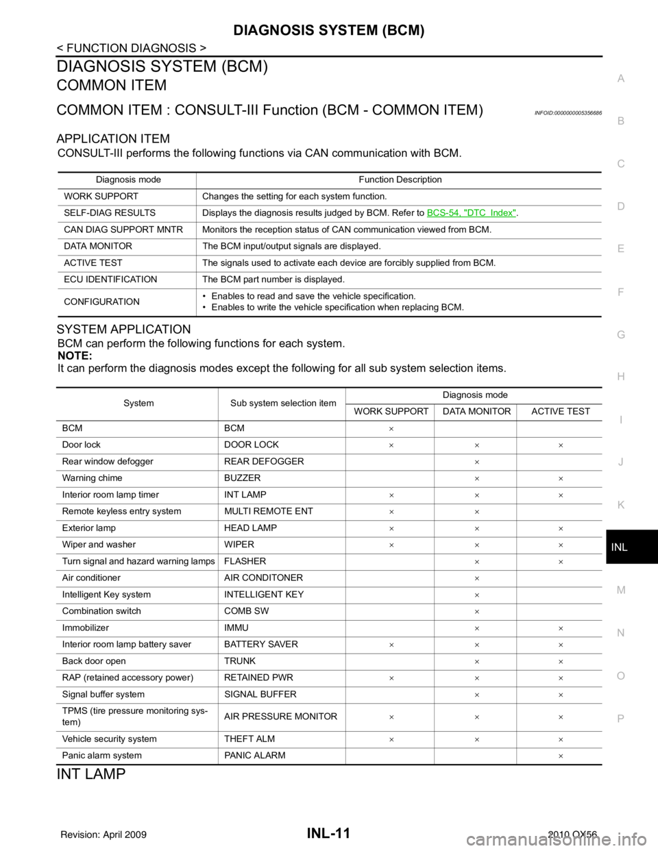
CONSULT-III performs the following functions via CAN communication with BCM.
SYSTEM APPLICATION
BCM can perform the following functions for each system.
NOTE:
It can perform the diagnosis modes except the following for all sub system selection items.
INT LAMP
Diagnosis mode Function Description
WORK SUPPORT Changes the setting for each system function.
SELF-DIAG RESULTS Displays the diagnosis results judged by BCM. Refer to BCS-54, "
DTCIndex".
CAN DIAG SUPPORT MNTR Monitors the reception status of CAN communication viewed from BCM.
DATA MONITOR The BCM input/output signals are displayed.
ACTIVE TEST The signals used to activate each device are forcibly supplied from BCM.
ECU IDENTIFICATION The BCM pa rt number is displayed.
CONFIGURATION • Enables to read and save the vehicle specification.
• Enables to write the vehicle specification when replacing BCM.
System
Sub system selection item Diagnosis mode
WORK SUPPORT DATA MONITOR ACTIVE TEST
BCM BCM ×
Door lock DOOR LOCK ×××
Rear window defogger REAR DEFOGGER ×
Warning chime BUZZER ××
Interior room lamp timer INT LAMP ×××
Remote keyless entry system MULTI REMOTE ENT ××
Exterior lamp HEAD LAMP ×××
Wiper and washer WIPER ×××
Turn signal and hazard warning lamps FLASHER ××
Air conditioner AIR CONDITONER ×
Intelligent Key system INTELLIGENT KEY ×
Combination switch COMB SW ×
Immobilizer IMMU ××
Interior room lamp battery saver BATTERY SAVER ×××
Back door open TRUNK ××
RAP (retained accessory power) RETAINED PWR ×××
Signal buffer system SIGNAL BUFFER ××
TPMS (tire pressure monitoring sys-
tem) AIR PRESSURE MONITOR
×××
Vehicle security system THEFT ALM ×××
Panic alarm system PANIC ALARM ×
Revision: April 20092010 QX56
Page 2557 of 4210
SQUEAK AND RATTLE TROUBLE DIAGNOSESINT-5
< SYMPTOM DIAGNOSIS >
C
DE
F
G H
I
K L
M A
B
INT
N
O P
2. Trunk lid striker out of adjustment
3. The trunk lid torsion bars knocking together
4. A loose license plate or bracket
Most of these incidents can be repaired by adjusting, se curing or insulating the item(s) or component(s) caus-
ing the noise.
SUNROOF/HEADLINING
Noises in the sunroof/headlining area can often be traced to one of the following:
1. Sunroof lid, rail, linkage or seals making a rattle or light knocking noise
2. Sun visor shaft shaking in the holder
3. Front or rear windshield touching headliner and squeaking
Again, pressing on the components to stop the noise while duplicating the conditions can isolate most of these
incidents. Repairs usually consist of insulating with felt cloth tape.
OVERHEAD CONSOLE (FRONT AND REAR)
Overhead console noises are often caused by the cons ole panel clips not being engaged correctly. Most of
these incidents are repaired by pushing up on the c onsole at the clip locations until the clips engage.
In addition look for:
1. Loose harness or harness connectors.
2. Front console map/reading lamp lens loose.
3. Loose screws at console attachment points.
SEATS
When isolating seat noise it's important to note the position the seat is in and the load placed on the seat when
the noise is present. These conditions should be duplicated when verifying and isolating the cause of the
noise.
Cause of seat noise include:
1. Headrest rods and holder
2. A squeak between the seat pad cushion and frame
3. The rear seatback lock and bracket
These noises can be isolated by moving or pressing on the suspected components while duplicating the con-
ditions under which the noise occurs. Most of thes e incidents can be repaired by repositioning the component
or applying urethane tape to the contact area.
UNDERHOOD
Some interior noise may be caused by components under the hood or on the engine wall. The noise is then
transmitted into the passenger compartment.
Causes of transmitted underhood noise include:
1. Any component installed to the engine wall
2. Components that pass through the engine wall
3. Engine wall mounts and connectors
4. Loose radiator installation pins
5. Hood bumpers out of adjustment
6. Hood striker out of adjustment
These noises can be difficult to isolate since they cannot be reached from the interior of the vehicle. The best
method is to secure, move or insulate one component at a time and test drive the vehicle. Also, engine RPM
or load can be changed to isolate the noise. Repairs can usually be made by moving, adjusting, securing, or
insulating the component causing the noise.
Revision: April 20092010 QX56
Page 2581 of 4210

IP-8
< SYMPTOM DIAGNOSIS >
SQUEAK AND RATTLE TROUBLE DIAGNOSES
3. The trunk lid torsion bars knocking together
4. A loose license plate or bracket
Most of these incidents can be repaired by adjusting, securing or insulating the item(s) or component(s) caus-
ing the noise.
SUNROOF/HEADLINING
Noises in the sunroof/headlining area c an often be traced to one of the following:
1. Sunroof lid, rail, linkage or seals making a rattle or light knocking noise
2. Sun visor shaft shaking in the holder
3. Front or rear windshield touching headliner and squeaking
Again, pressing on the components to stop the noise while duplicating the conditions can isolate most of these
incidents. Repairs usually consist of insulating with felt cloth tape.
OVERHEAD CONSOLE (FRONT AND REAR)
Overhead console noises are often caused by the c onsole panel clips not being engaged correctly. Most of
these incidents are repaired by pushing up on the c onsole at the clip locations until the clips engage.
In addition look for:
1. Loose harness or harness connectors.
2. Front console map/reading lamp lens loose.
3. Loose screws at console attachment points.
SEATS
When isolating seat noise it's important to note the pos ition the seat is in and the load placed on the seat when
the noise is present. These conditions should be duplicated when verifying and isolating the cause of the
noise.
Cause of seat noise include:
1. Headrest rods and holder
2. A squeak between the seat pad cushion and frame
3. The rear seatback lock and bracket
These noises can be isolated by moving or pressing on the suspected components while duplicating the con-
ditions under which the noise occurs. Most of thes e incidents can be repaired by repositioning the component
or applying urethane tape to the contact area.
UNDERHOOD
Some interior noise may be caused by components under the hood or on the engine wall. The noise is then
transmitted into the passenger compartment.
Causes of transmitted underhood noise include:
1. Any component mounted to the engine wall
2. Components that pass through the engine wall
3. Engine wall mounts and connectors
4. Loose radiator mounting pins
5. Hood bumpers out of adjustment
6. Hood striker out of adjustment
These noises can be difficult to isolate since they cannot be reached from the interior of the vehicle. The best
method is to secure, move or insulate one component at a time and test drive the \
vehicle. Also, engine RPM
or load can be changed to isolate the noise. Repairs can usually be made by moving, adjusting, securing, or
insulating the component causing the noise.
Revision: April 20092010 QX56
Page 2696 of 4210
LU-10
< ON-VEHICLE MAINTENANCE >
ENGINE OIL
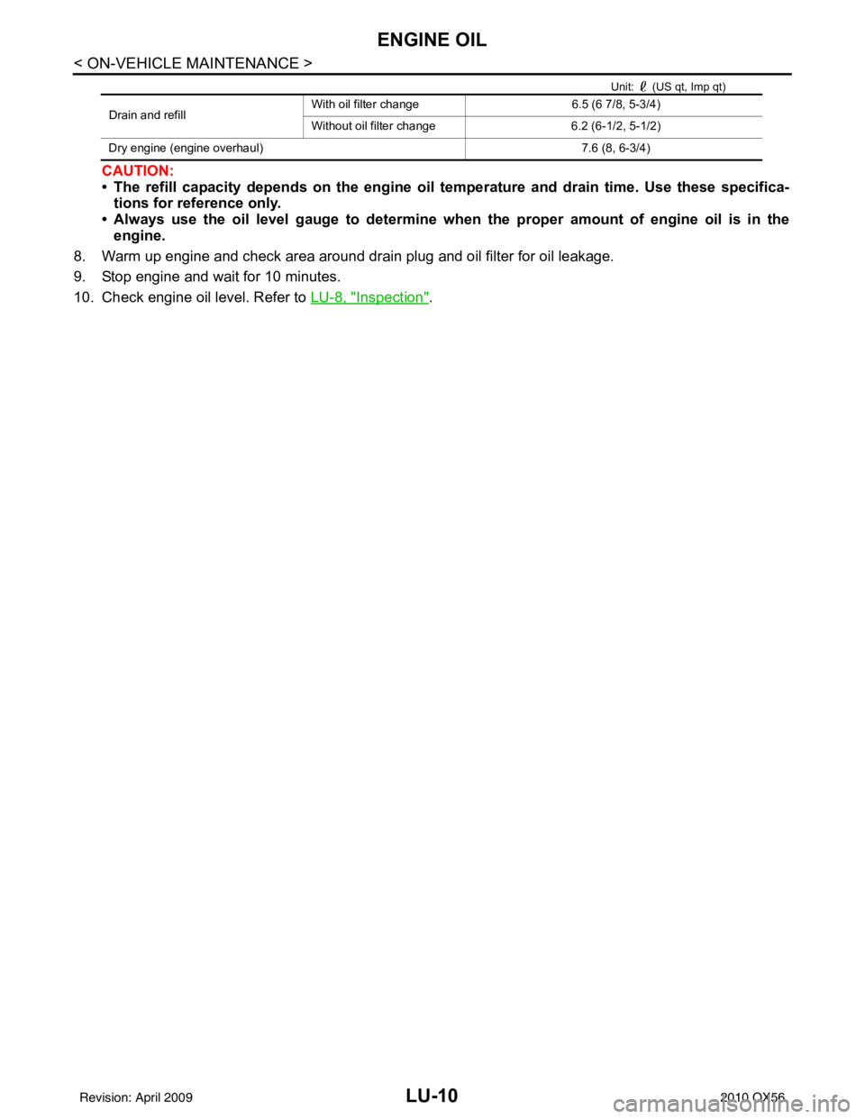
Unit: (US qt, Imp qt)
CAUTION:
• The refill capacity depends on the engine oil temperature and drain time. Use these specifica-
tions for reference only.
• Always use the oil level gauge to determine when the proper amount of engine oil is in the engine.
8. Warm up engine and check area around drain plug and oil filter for oil leakage.
9. Stop engine and wait for 10 minutes.
10. Check engine oil level. Refer to LU-8, "
Inspection".
Drain and refill With oil filter change
6.5 (6 7/8, 5-3/4)
Without oil filter change 6.2 (6-1/2, 5-1/2)
Dry engine (engine overhaul) 7.6 (8, 6-3/4)
Revision: April 20092010 QX56
Page 2710 of 4210
MA-6
< ON-VEHICLE MAINTENANCE >
GENERAL MAINTENANCE
ON-VEHICLE MAINTENANCE
GENERAL MAINTENANCE
General MaintenanceINFOID:0000000005145933
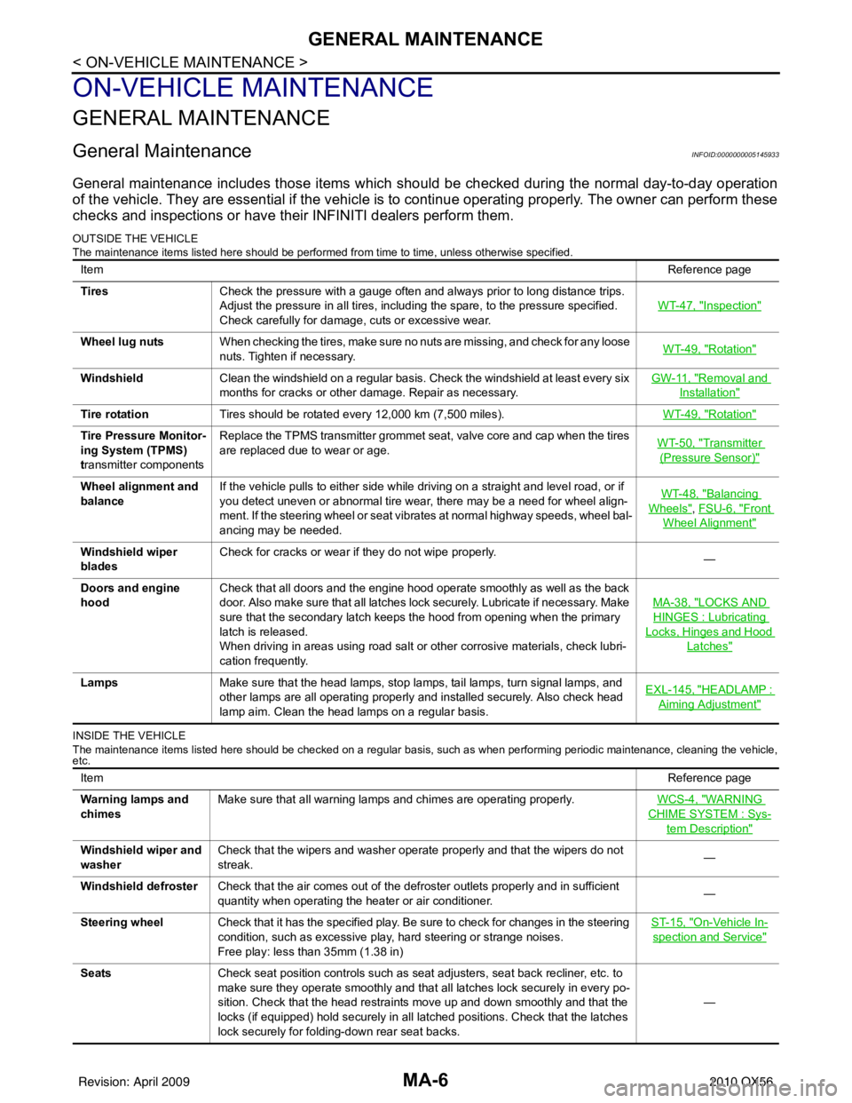
General maintenance includes those items which should be checked during the normal day-to-day operation
of the vehicle. They are essential if the vehicle is to continue operating properly. The owner can perform these
checks and inspections or have thei r INFINITI dealers perform them.
OUTSIDE THE VEHICLE
The maintenance items listed here should be performed fr om time to time, unless otherwise specified.
INSIDE THE VEHICLE
The maintenance items listed here should be checked on a regular basis, such as when performing periodic maintenance, cleaning the vehicle,
etc.
Item Reference page
Tires Check the pressure with a gauge often and always prior to long distance trips.
Adjust the pressure in all tires, including the spare, to the pressure specified.
Check carefully for damage, cuts or excessive wear. WT-47, "
Inspection"
Wheel lug nuts
When checking the tires, make sure no nuts are missing, and check for any loose
nuts. Tighten if necessary. WT-49, "Rotation"
Windshield
Clean the windshield on a regular basis. Check the windshield at least every six
months for cracks or other damage. Repair as necessary. GW-11, "Removal and
Installation"
Tire rotation
Tires should be rotated every 12,000 km (7,500 miles). WT-49, "Rotation"
Tire Pressure Monitor-
ing System (TPMS)
transmitter componentsReplace the TPMS transmitter grommet seat, valve core and cap when the tires
are replaced due to wear or age.
WT-50, "Transmitter
(Pressure Sensor)"
Wheel alignment and
balanceIf the vehicle pulls to either side while driving on a straight and level road, or if
you detect uneven or abnormal tire wear, there may be a need for wheel align-
ment. If the steering wheel or seat vibrates at normal highway speeds, wheel bal-
ancing may be needed. WT-48, "Balancing
Wheels", FSU-6, "Front
Wheel Alignment"
Windshield wiper
blades
Check for cracks or wear if they do not wipe properly.
—
Doors and engine
hood Check that all doors and the engine hood operate smoothly as well as the back
door. Also make sure that all latches lock securely. Lubricate if necessary. Make
sure that the secondary latch keeps the hood from opening when the primary
latch is released.
When driving in areas using road salt or other corrosive materials, check lubri-
cation frequently. MA-38, "
LOCKS AND
HINGES : Lubricating
Locks, Hinges and Hood
Latches"
Lamps
Make sure that the head lamps, stop lamps, tail lamps, turn signal lamps, and
other lamps are all operating properly and installed securely. Also check head
lamp aim. Clean the head lamps on a regular basis. EXL-145, "HEADLAMP :
Aiming Adjustment"
Item
Reference page
Warning lamps and
chimes Make sure that all warning lamps and chimes are operating properly.
WCS-4, "
WARNING
CHIME SYSTEM : Sys-
tem Description"
Windshield wiper and
washerCheck that the wipers and washer operate properly and that the wipers do not
streak.
—
Windshield defroster Check that the air comes out of the defroster outlets properly and in sufficient
quantity when operating the heater or air conditioner. —
Steering wheel Check that it has the specified play. Be sure to check for changes in the steering
condition, such as excessive play, hard steering or strange noises.
Free play: less than 35mm (1.38 in) ST-15, "
On-Vehicle In-
spection and Service"
Seats
Check seat position controls such as seat adjusters, seat back recliner, etc. to
make sure they operate smoothly and that all latches lock securely in every po-
sition. Check that the head restraints move up and down smoothly and that the
locks (if equipped) hold securely in all latched positions. Check that the latches
lock securely for folding-down rear seat backs. —
Revision: April 20092010 QX56
Page 2726 of 4210
MA-22
< ON-VEHICLE MAINTENANCE >
ENGINE MAINTENANCE
8. After the inspections, install oil pressure switch as follows:
a. Remove old liquid gasket adhering to oil pressure switch and engine.
b. Apply liquid gasket and tighten oil pressure switch to the specification.Use Genuine RTV Silicone Seal ant or equivalent. Refer to GI-15, "
Recommended Chemical Prod-
ucts and Sealants".
c. After warming up engine, make sure there is no leakage of engine oil with engine running.
ENGINE OIL : Changing Engine OilINFOID:0000000005403141
WARNING:
• Be careful not to burn yoursel f, as the engine oil is hot.
• Prolonged and repeated contact with used engine oil may
cause skin cancer. Try to avoid di rect skin contact with used
engine oil. If skin contact is made, wash thoroughly with soap
or hand cleaner as soon as possible.
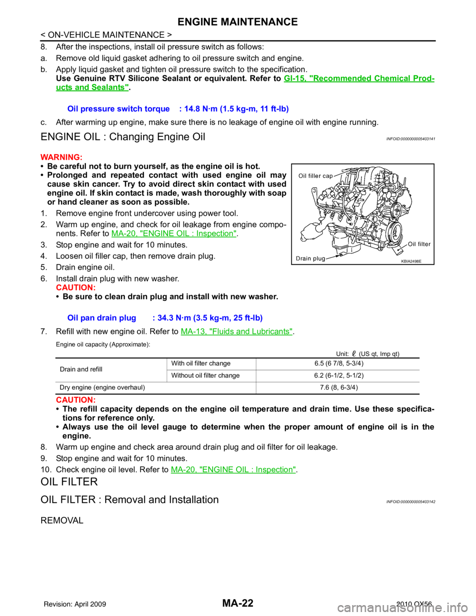
1. Remove engine front undercover using power tool.
2. Warm up engine, and check for oil leakage from engine compo- nents. Refer to MA-20, "
ENGINE OIL : Inspection".
3. Stop engine and wait for 10 minutes.
4. Loosen oil filler cap, then remove drain plug.
5. Drain engine oil.
6. Install drain plug with new washer. CAUTION:
• Be sure to clean drain plug and install with new washer.
7. Refill with new engine oil. Refer to MA-13, "
Fluids and Lubricants".
Engine oil capacity (Approximate):
Unit: (US qt, Imp qt)
CAUTION:
• The refill capacity depends on the engine oil temperature and drain time. Use these specifica-
tions for reference only.
• Always use the oil level gauge to determine when the proper amount of engine oil is in the engine.
8. Warm up engine and check area around drain plug and oil filter for oil leakage.
9. Stop engine and wait for 10 minutes.
10. Check engine oil level. Refer to MA-20, "
ENGINE OIL : Inspection".
OIL FILTER
OIL FILTER : Removal and InstallationINFOID:0000000005403142
REMOVAL
Oil pressure switch torque : 14.8 N·m (1.5 kg-m, 11 ft-lb)
Oil pan drain plug : 34.3 N·m (3.5 kg-m, 25 ft-lb)
KBIA2498E
Drain and refill With oil filter change
6.5 (6 7/8, 5-3/4)
Without oil filter change 6.2 (6-1/2, 5-1/2)
Dry engine (engine overhaul) 7.6 (8, 6-3/4)
Revision: April 20092010 QX56
Page 2821 of 4210
MWI
COMBINATION METERMWI-59
< ECU DIAGNOSIS >
C
DE
F
G H
I
J
K L
M B A
O P
DTC IndexINFOID:0000000005146101
NOTE:
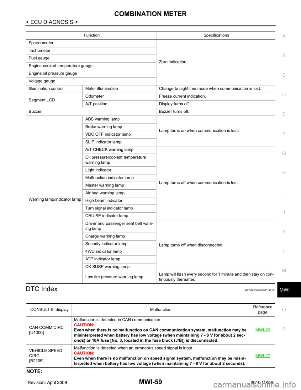
Function Specifications
Speedometer
Zero indication.
Tachometer
Fuel gauge
Engine coolant temperature gauge
Engine oil pressure gauge
Voltage gauge
Illumination control
Meter illumination Change to nighttime mode when communication is lost.
Segment LCD Odometer
Freeze current indication.
A/T position Display turns off.
Buzzer Buzzer turns off.
Warning lamp/indicator lamp ABS warning lamp
Lamp turns on when communication is lost.
Brake warning lamp
VDC OFF indicator lamp
SLIP indicator lamp
A/T CHECK warning lamp
Lamp turns off when communication is lost.
Oil pressure/coolant temperature
warning lamp
Light indicator
Malfunction indicator lamp
Master warning lamp
Air bag warning lamp
High beam indicator
Turn signal indicator lamp
CRUISE indicator lamp
Driver and passenger seat belt warn-
ing lamp
Lamp turns off when disconnected.
Charge warning lamp
Security indicator lamp
4WD indicator lamp
ATP indicator lamp
CK SUSP warning lamp
Low tire pressu
re warning lamp Lamp will flash every second for 1 minute and then stay on con-
tinuously thereafter.
CONSULT-III display
MalfunctionReference
page
CAN COMM CIRC
[U1000] Malfunction is detected in CAN communication.
CAUTION:
Even when there is no ma
lfunction on CAN communication system, malfunction may be
misinterpreted when battery has low voltag e (when maintaining 7 - 8 V for about 2 sec-
onds) or 10A fuse [No. 3, located in the fuse block (J/B)] is disconnected. MWI-26
VEHICLE SPEED
CIRC
[B2205]Malfunction is detected when an erroneous speed signal is input.
CAUTION:
Even when there is no malfunction on speed signal system, malfunction may be misin-
terpreted when battery has low voltage (whe
n maintaining 7 - 8 V for about 2 seconds). MWI-27
Revision: April 20092010 QX56