2010 INFINITI QX56 change time
[x] Cancel search: change timePage 3754 of 4210

P0733 3GR INCORRECT RATIOTM-59
< COMPONENT DIAGNOSIS >
CEF
G H
I
J
K L
M A
B
TM
N
O P
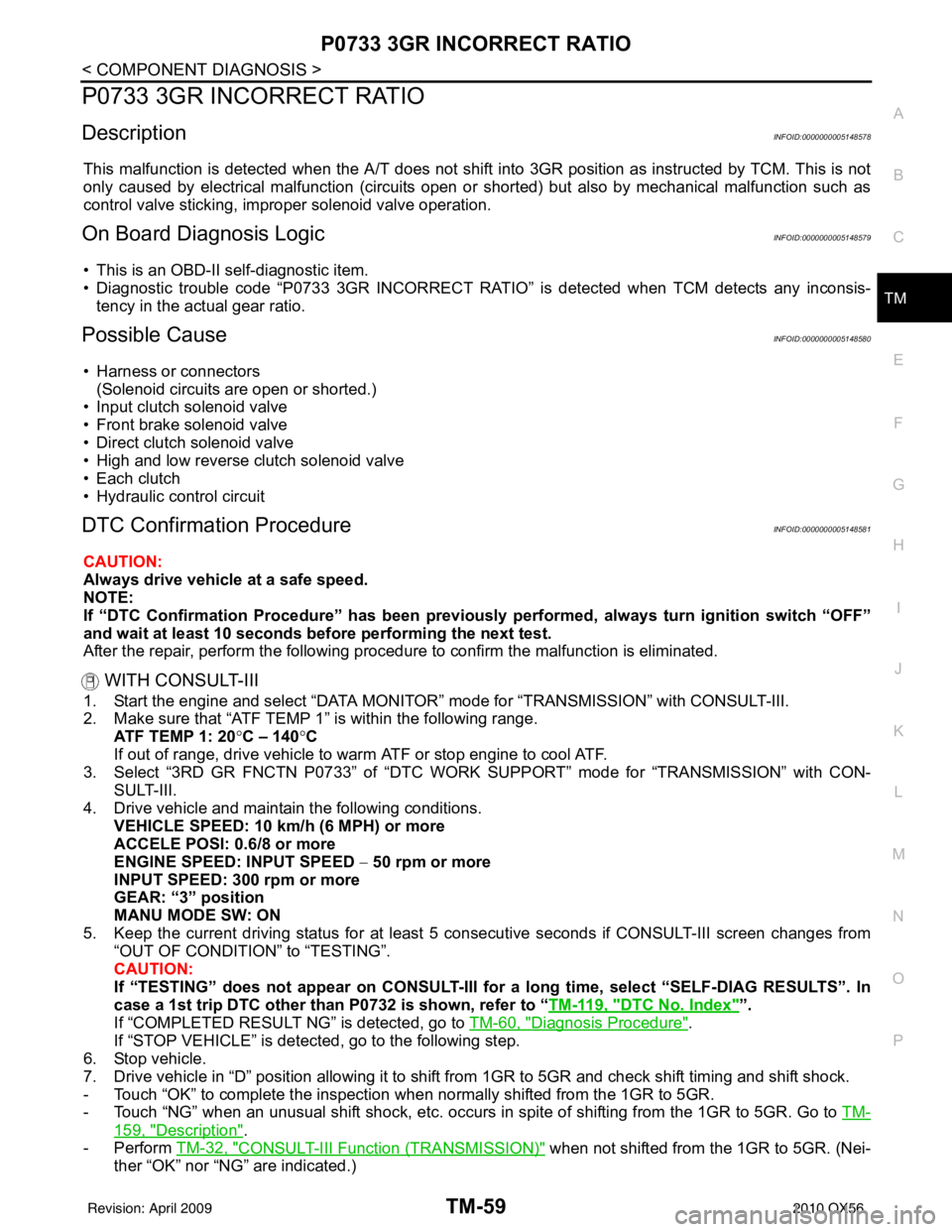
P0733 3GR INCORRECT RATIO
DescriptionINFOID:0000000005148578
This malfunction is detected when the A/T does not shift into 3GR position as instructed by TCM. This is not
only caused by electrical malfunction (circuits open or shorted) but also by mechanical malfunction such as
control valve sticking, improper solenoid valve operation.
On Board Diagnosis LogicINFOID:0000000005148579
• This is an OBD-II self-diagnostic item.
• Diagnostic trouble code “P0733 3GR INCORRECT RATIO” is detected when TCM detects any inconsis-
tency in the actual gear ratio.
Possible CauseINFOID:0000000005148580
• Harness or connectors (Solenoid circuits are open or shorted.)
• Input clutch solenoid valve
• Front brake solenoid valve
• Direct clutch solenoid valve
• High and low reverse clutch solenoid valve
• Each clutch
• Hydraulic control circuit
DTC Confirmation ProcedureINFOID:0000000005148581
CAUTION:
Always drive vehicle at a safe speed.
NOTE:
If “DTC Confirmation Procedure” has been previously performed, always turn ignition switch “OFF”
and wait at least 10 seconds before performing the next test.
After the repair, perform the following procedure to confirm the malfunction is eliminated.
WITH CONSULT-III
1. Start the engine and select “DATA MONITOR” mode for “TRANSMISSION” with CONSULT-III.
2. Make sure that “ATF TEMP 1” is within the following range. ATF TEMP 1: 20 °C – 140 °C
If out of range, drive vehicle to warm ATF or stop engine to cool ATF.
3. Select “3RD GR FNCTN P0733” of “DTC WORK SUPPORT” mode for “TRANSMISSION” with CON-
SULT-III.
4. Drive vehicle and maintain the following conditions. VEHICLE SPEED: 10 km/h (6 MPH) or more
ACCELE POSI: 0.6/8 or more
ENGINE SPEED: INPUT SPEED − 50 rpm or more
INPUT SPEED: 300 rpm or more
GEAR: “3” position
MANU MODE SW: ON
5. Keep the current driving status for at least 5 consecutive seconds if CONSULT-III screen changes from “OUT OF CONDITION” to “TESTING”.
CAUTION:
If “TESTING” does not appear on CONSULT-III for a long time, select “SELF-DIAG RESULTS”. In
case a 1st trip DTC other than P0732 is shown, refer to “ TM-119, "
DTC No. Index"”.
If “COMPLETED RESULT NG” is detected, go to TM-60, "
Diagnosis Procedure".
If “STOP VEHICLE” is detec ted, go to the following step.
6. Stop vehicle.
7. Drive vehicle in “D” position allowing it to shift from 1GR to 5GR and check shift timing and shift shock.
- Touch “OK” to complete the inspection when normally shifted from the 1GR to 5GR.
- Touch “NG” when an unusual shift shock, etc. occurs in spite of shifting from the 1GR to 5GR. Go to TM-
159, "Description".
-Perform TM-32, "
CONSULT-III Functi on (TRANSMISSION)" when not shifted from the 1GR to 5GR. (Nei-
ther “OK” nor “NG” are indicated.)
Revision: April 20092010 QX56
Page 3756 of 4210

P0734 4GR INCORRECT RATIOTM-61
< COMPONENT DIAGNOSIS >
CEF
G H
I
J
K L
M A
B
TM
N
O P
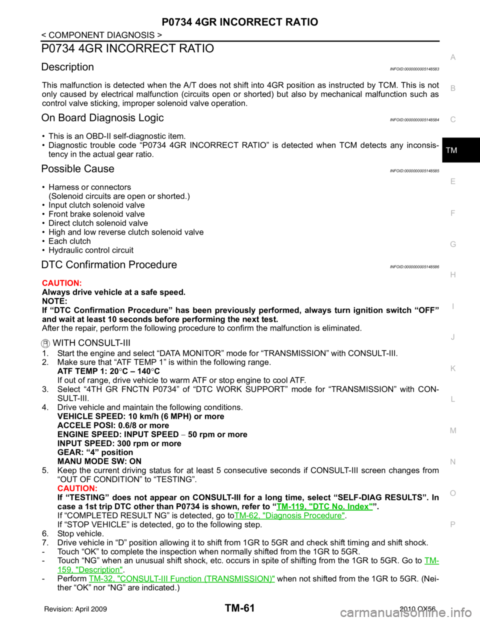
P0734 4GR INCORRECT RATIO
DescriptionINFOID:0000000005148583
This malfunction is detected when the A/T does not shift into 4GR position as instructed by TCM. This is not
only caused by electrical malfunction (circuits open or shorted) but also by mechanical malfunction such as
control valve sticking, improper solenoid valve operation.
On Board Diagnosis LogicINFOID:0000000005148584
• This is an OBD-II self-diagnostic item.
• Diagnostic trouble code “P0734 4GR INCORRECT RATIO” is detected when TCM detects any inconsis-
tency in the actual gear ratio.
Possible CauseINFOID:0000000005148585
• Harness or connectors (Solenoid circuits are open or shorted.)
• Input clutch solenoid valve
• Front brake solenoid valve
• Direct clutch solenoid valve
• High and low reverse clutch solenoid valve
• Each clutch
• Hydraulic control circuit
DTC Confirmation ProcedureINFOID:0000000005148586
CAUTION:
Always drive vehicle at a safe speed.
NOTE:
If “DTC Confirmation Procedure” has been previously performed, always turn ignition switch “OFF”
and wait at least 10 seconds before performing the next test.
After the repair, perform the following procedure to confirm the malfunction is eliminated.
WITH CONSULT-III
1. Start the engine and select “DATA MONITOR” mode for “TRANSMISSION” with CONSULT-III.
2. Make sure that “ATF TEMP 1” is within the following range. ATF TEMP 1: 20 °C – 140 °C
If out of range, drive vehicle to warm ATF or stop engine to cool ATF.
3. Select “4TH GR FNCTN P0734” of “DTC WORK SUPPORT” mode for “TRANSMISSION” with CON-
SULT-III.
4. Drive vehicle and maintain the following conditions. VEHICLE SPEED: 10 km/h (6 MPH) or more
ACCELE POSI: 0.6/8 or more
ENGINE SPEED: INPUT SPEED − 50 rpm or more
INPUT SPEED: 300 rpm or more
GEAR: “4” position
MANU MODE SW: ON
5. Keep the current driving status for at least 5 consecutive seconds if CONSULT-III screen changes from “OUT OF CONDITION” to “TESTING”.
CAUTION:
If “TESTING” does not appear on CONSULT-III for a long time, select “SELF-DIAG RESULTS”. In
case a 1st trip DTC other than P0734 is shown, refer to “ TM-119, "
DTC No. Index"”.
If “COMPLETED RESULT NG” is detected, go toTM-62, "
Diagnosis Procedure".
If “STOP VEHICLE” is detec ted, go to the following step.
6. Stop vehicle.
7. Drive vehicle in “D” position allowing it to shift from 1GR to 5GR and check shift timing and shift shock.
- Touch “OK” to complete the inspection when normally shifted from the 1GR to 5GR.
- Touch “NG” when an unusual shift shock, etc. occurs in spite of shifting from the 1GR to 5GR. Go to TM-
159, "Description".
-Perform TM-32, "
CONSULT-III Functi on (TRANSMISSION)" when not shifted from the 1GR to 5GR. (Nei-
ther “OK” nor “NG” are indicated.)
Revision: April 20092010 QX56
Page 3758 of 4210

P0735 5GR INCORRECT RATIOTM-63
< COMPONENT DIAGNOSIS >
CEF
G H
I
J
K L
M A
B
TM
N
O P
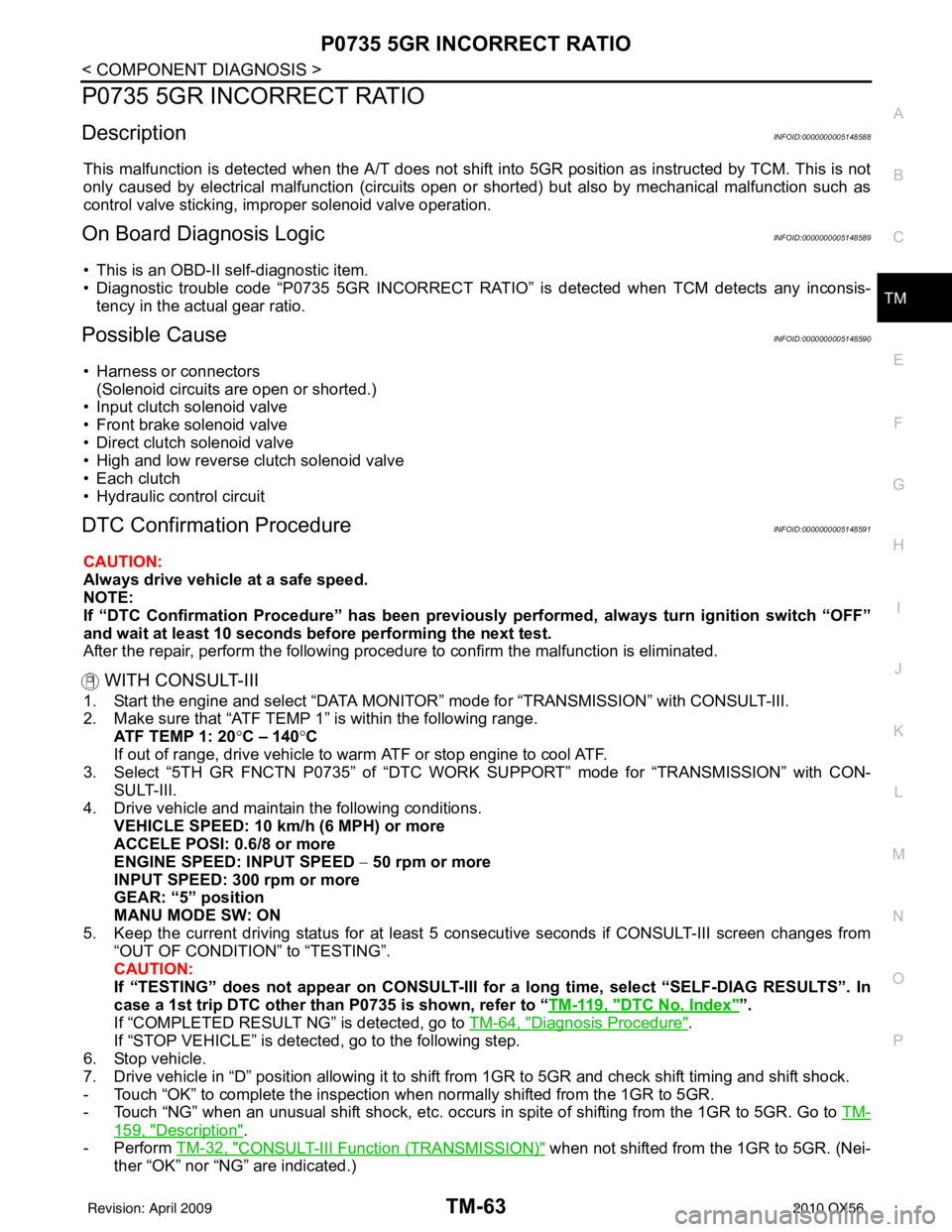
P0735 5GR INCORRECT RATIO
DescriptionINFOID:0000000005148588
This malfunction is detected when the A/T does not shift into 5GR position as instructed by TCM. This is not
only caused by electrical malfunction (circuits open or shorted) but also by mechanical malfunction such as
control valve sticking, improper solenoid valve operation.
On Board Diagnosis LogicINFOID:0000000005148589
• This is an OBD-II self-diagnostic item.
• Diagnostic trouble code “P0735 5GR INCORRECT RATIO” is detected when TCM detects any inconsis-
tency in the actual gear ratio.
Possible CauseINFOID:0000000005148590
• Harness or connectors (Solenoid circuits are open or shorted.)
• Input clutch solenoid valve
• Front brake solenoid valve
• Direct clutch solenoid valve
• High and low reverse clutch solenoid valve
• Each clutch
• Hydraulic control circuit
DTC Confirmation ProcedureINFOID:0000000005148591
CAUTION:
Always drive vehicle at a safe speed.
NOTE:
If “DTC Confirmation Procedure” has been previously performed, always turn ignition switch “OFF”
and wait at least 10 seconds before performing the next test.
After the repair, perform the following procedure to confirm the malfunction is eliminated.
WITH CONSULT-III
1. Start the engine and select “DATA MONITOR” mode for “TRANSMISSION” with CONSULT-III.
2. Make sure that “ATF TEMP 1” is within the following range. ATF TEMP 1: 20 °C – 140 °C
If out of range, drive vehicle to warm ATF or stop engine to cool ATF.
3. Select “5TH GR FNCTN P0735” of “DTC WORK SUPPORT” mode for “TRANSMISSION” with CON-
SULT-III.
4. Drive vehicle and maintain the following conditions. VEHICLE SPEED: 10 km/h (6 MPH) or more
ACCELE POSI: 0.6/8 or more
ENGINE SPEED: INPUT SPEED − 50 rpm or more
INPUT SPEED: 300 rpm or more
GEAR: “5” position
MANU MODE SW: ON
5. Keep the current driving status for at least 5 consecutive seconds if CONSULT-III screen changes from “OUT OF CONDITION” to “TESTING”.
CAUTION:
If “TESTING” does not appear on CONSULT-III for a long time, select “SELF-DIAG RESULTS”. In
case a 1st trip DTC other than P0735 is shown, refer to “ TM-119, "
DTC No. Index"”.
If “COMPLETED RESULT NG” is detected, go to TM-64, "
Diagnosis Procedure".
If “STOP VEHICLE” is detec ted, go to the following step.
6. Stop vehicle.
7. Drive vehicle in “D” position allowing it to shift from 1GR to 5GR and check shift timing and shift shock.
- Touch “OK” to complete the inspection when normally shifted from the 1GR to 5GR.
- Touch “NG” when an unusual shift shock, etc. occurs in spite of shifting from the 1GR to 5GR. Go to TM-
159, "Description".
-Perform TM-32, "
CONSULT-III Functi on (TRANSMISSION)" when not shifted from the 1GR to 5GR. (Nei-
ther “OK” nor “NG” are indicated.)
Revision: April 20092010 QX56
Page 3801 of 4210

TM-106
< ECU DIAGNOSIS >
TCM
ECU DIAGNOSIS
TCM
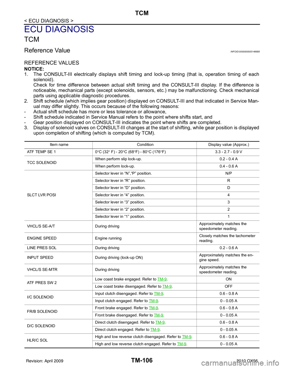
Reference ValueINFOID:0000000005148688
REFERENCE VALUES
NOTICE:
1. The CONSULT-III electrically displays shift timing and lock-up timing (that is, operation timing of eachsolenoid).
Check for time difference between actual shift timi ng and the CONSULT-III display. If the difference is
noticeable, mechanical parts (except solenoids, sens ors, etc.) may be malfunctioning. Check mechanical
parts using applicable diagnostic procedures.
2. Shift schedule (which implies gear position) display ed on CONSULT-III and that indicated in Service Man-
ual may differ slightly. This occurs because of the following reasons:
- Actual shift schedule has more or less tolerance or allowance,
- Shift schedule indicated in Service Manual refers to the point where shifts start, and
- Gear position displayed on CONSULT-III indicates the point where shifts are completed.
3. Display of solenoid valves on CONSULT-III changes at t he start of shifting, while gear position is displayed
upon completion of shifting (which is computed by TCM).
Item name Condition Display value (Approx.)
AT F T E M P S E 1 0°C (32 ° F) - 20 °C (68 °F) - 80 °C (176 °F) 3.3 - 2.7 - 0.9 V
TCC SOLENOID When perform slip lock-up.
0.2 - 0.4 A
When perform lock-up. 0.4 - 0.6 A
SLCT LVR POSI Selector lever in “N”,“P” position.
N/P
Selector lever in “R” position. R
Selector lever in “D” position. D
Selector lever in “4” position. 4
Selector lever in “3” position. 3
Selector lever in “2” position. 2
Selector lever in “1” position. 1
VHCL/S SE-A/T During driving Approximately matches the
speedometer reading.
ENGINE SPEED Engine running Closely matches the tachometer
reading.
LINE PRES SOL During driving 0.2 - 0.6 A
INPUT SPEED During driving (lock-up ON) Approximately matches the en-
gine speed.
VHCL/S SE-MTR During driving Approximately matches the
speedometer reading.
ATF PRES SW 2 Low coast brake engaged. Refer to
TM-9
.ON
Low coast brake disengaged. Refer to TM-9
.OFF
I/C SOLENOID Input clutch disengaged. Refer to
TM-9
.0.6 - 0 .8 A
Input clutch engaged. Refer to TM-9
.0 - 0 .0 5 A
FR/B SOLENOID Front brake engaged. Refer to
TM-9
.0 .6 - 0 .8 A
Front brake disengaged. Refer to TM-9
.0 - 0 .0 5 A
D/C SOLENOID Direct clutch disengaged. Refer to
TM-9
.0.6 - 0 .8 A
Direct clutch engaged. Refer to TM-9
.0 - 0 .0 5 A
HLR/C SOL High and low reverse clutch disengaged. Refer to
TM-9
.0.6 - 0 .8 A
High and low reverse clutch engaged. Refer to TM-9
.0 - 0 .0 5 A
Revision: April 20092010 QX56
Page 4047 of 4210

WCS-48
< ECU DIAGNOSIS >
COMBINATION METER
DTC Index
INFOID:0000000005382411
NOTE:
Function Specifications
Speedometer
Zero indication.
Tachometer
Fuel gauge
Engine coolant temperature gauge
Engine oil pressure gauge
Voltage gauge
Illumination control
Meter illumination Change to nighttime mode when communication is lost.
Segment LCD Odometer
Freeze current indication.
A/T position Display turns off.
Buzzer Buzzer turns off.
Warning lamp/indicator lamp ABS warning lamp
Lamp turns on when communication is lost.
Brake warning lamp
VDC OFF indicator lamp
SLIP indicator lamp
A/T CHECK warning lamp
Lamp turns off when communication is lost.
Oil pressure/coolant temperature
warning lamp
Light indicator
Malfunction indicator lamp
Master warning lamp
Air bag warning lamp
High beam indicator
Turn signal indicator lamp
CRUISE indicator lamp
Driver and passenger seat belt warn-
ing lamp
Lamp turns off when disconnected.
Charge warning lamp
Security indicator lamp
4WD indicator lamp
AT P i n d i c a t o r l a m p
CK SUSP warning lamp
Low tire pressure warning lamp
Lamp will flash every second for 1 minute and then stay on con-
tinuously thereafter.
CONSULT-III display
MalfunctionReference
page
CAN COMM CIRC
[U1000] Malfunction is detected in CAN communication.
CAUTION:
Even when there is no malfunction on CAN communication system, malfunction may be
misinterpreted when battery has low voltage (when maintaining 7 - 8 V for about 2 sec-
onds) or 10A fuse [No. 3, located in
the fuse block (J/B)] is disconnected. MWI-26
VEHICLE SPEED
CIRC
[B2205]Malfunction is detected when an erroneous speed signal is input.
CAUTION:
Even when there is no malfunction on speed signal system, malfunction may be misin-
terpreted when battery has lo
w voltage (when maintaining 7 - 8 V for about 2 seconds). MWI-27
Revision: April 20092010 QX56
Page 4132 of 4210

DIAGNOSIS SYSTEM (BCM)WW-11
< FUNCTION DIAGNOSIS >
C
DE
F
G H
I
J
K
M A
B
WW
N
O P
DIAGNOSIS SYSTEM (BCM)
COMMON ITEM
COMMON ITEM : CONSULT-III Fu nction (BCM - COMMON ITEM)INFOID:0000000005369209
APPLICATION ITEM
CONSULT-III performs the following functions via CAN communication with BCM.
SYSTEM APPLICATION
BCM can perform the following functions for each system.
NOTE:
It can perform the diagnosis modes except the following for all sub system selection items.
WIPER
Diagnosis mode Function Description
WORK SUPPORT Changes the setting for each system function.
SELF-DIAG RESULTS Displays the diagnosis results judged by BCM. Refer to BCS-54, "
DTCIndex".
CAN DIAG SUPPORT MNTR Monitors the reception status of CAN communication viewed from BCM.
DATA MONITOR The BCM input/output signals are displayed.
ACTIVE TEST The signals used to activate each device are forcibly supplied from BCM.
ECU IDENTIFICATION The BCM pa rt number is displayed.
CONFIGURATION • Enables to read and save the vehicle specification.
• Enables to write the vehicle specification when replacing BCM.
System
Sub system selection item Diagnosis mode
WORK SUPPORT DATA MONITOR ACTIVE TEST
BCM BCM ×
Door lock DOOR LOCK ×××
Rear window defogger REAR DEFOGGER ×
Warning chime BUZZER ××
Interior room lamp timer INT LAMP ×××
Remote keyless entry system MULTI REMOTE ENT ××
Exterior lamp HEAD LAMP ×××
Wiper and washer WIPER ×××
Turn signal and hazard warning lamps FLASHER ××
Air conditioner AIR CONDITONER ×
Intelligent Key system INTELLIGENT KEY ×
Combination switch COMB SW ×
Immobilizer IMMU ××
Interior room lamp battery saver BATTERY SAVER ×××
Back door open TRUNK ××
RAP (retained accessory power) RETAINED PWR ×××
Signal buffer system SIGNAL BUFFER ××
TPMS (tire pressure monitoring sys-
tem) AIR PRESSURE MONITOR
×××
Vehicle security system THEFT ALM ×××
Panic alarm system PANIC ALARM ×
Revision: April 20092010 QX56
Page 4178 of 4210

IPDM E/R (INTELLIGENT POWER DISTRIBUTION MODULE ENGINE ROOM)
WW-57
< ECU DIAGNOSIS >
C
D E
F
G H
I
J
K
M A
B
WW
N
O P
IPDM E/R (INTELLIGENT POWER DISTRIBUTION MODULE ENGINE
ROOM)
Reference ValueINFOID:0000000005369222
VALUES ON THE DIAGNOSIS TOOL
Monitor Item ConditionValue/Status
MOTOR FAN REQ Engine idle speed Changes depending on engine
coolant temperature, air conditioner
operation status, vehicle speed,
etc.0 - 100 %
A/C COMP REQ A/C switch OFF
OFF
A/C switch ON ON
TA I L & C L R R E Q Lighting switch OFF
OFF
Lighting switch 1ST, 2ND, HI or AUTO (Light is illuminated) ON
HL LO REQ Lighting switch OFF
OFF
Lighting switch 2ND HI or AUTO (Light is illuminated) ON
HL HI REQ Lighting switch OFF
OFF
Lighting switch HI ON
FR FOG REQ Lighting switch 2ND or AUTO (Light
is illuminated) Front fog lamp switch OFF OFF
• Front fog lamp switch ON
• Daytime light activated (Canada
only) ON
FR WIP REQ Ignition switch ON Front wiper switch OFF
STOP
Front wiper switch INT 1LOW
Front wiper switch LO LOW
Front wiper switch HI HI
WIP AUTO STOP Ignition switch ON Front wiper stop position
STOP P
Any position other than front wiper
stop position ACT P
WIP PROT Ignition switch ON Front wiper operates normally OFF
Front wiper stops at fail-safe opera-
tion
BLOCK
ST RLY REQ Ignition switch OFF or ACC
OFF
Ignition switch START ON
IGN RLY Ignition switch OFF or ACC
OFF
Ignition switch ON ON
RR DEF REQ Rear defogger switch OFF
OFF
Rear defogger switch ON ON
OIL P SW Ignition switch OFF, ACC or engine running
OPEN
Ignition switch ON CLOSE
DTRL REQ Daytime light system requested OFF with CONSULT-III.
OFF
Daytime light system reques ted ON with CONSULT-III. ON
HOOD SW Hood closed.
OFF
Hood open. ON
Revision: April 20092010 QX56
Page 4190 of 4210

IPDM E/R (INTELLIGENT POWER DISTRIBUTION MODULE ENGINE ROOM)
WW-69
< ECU DIAGNOSIS >
C
D E
F
G H
I
J
K
M A
B
WW
N
O P
If No CAN Communication Is Available With BCM
IGNITION RELAY MALFUNCTION DETECTION FUNCTION
• IPDM E/R monitors the voltage at the contact circuit and excitation coil circuit of the ignition relay inside it.
• IPDM E/R judges the ignition relay error if the voltage differs between the contact circuit and the excitation
coil circuit.
• If the ignition relay cannot turn OFF due to contact seizure, it activates the tail lamp relay for 10 minutes to alert the user to the ignition relay malfunction when the ignition switch is turned OFF.
NOTE:
The tail lamp turns OFF when the ignition switch is turned ON.
FRONT WIPER CONTROL
IPDM E/R detects front wiper stop posit ion by a front wiper auto stop signal.
When a front wiper auto stop signal is in the conditions listed below, IPDM E/R stops power supply to wiper
after repeating a front wiper 10 second activation and 20 second stop five times.
NOTE:
This operation status can be confirmed on the IPDM E/R “DATA MONITOR” that displays “Block” for the item
“WIP PROT” while the wiper is stopped.
STARTER MOTOR PROTECTION FUNCTION
IPDM E/R turns OFF the starter control relay to protect the starter motor when the starter control relay remains
active for 90 seconds.
Control part Fail-safe in operation
Cooling fan • Turns ON the cooling fan relay when the ignition switch is turned ON
• Turns OFF the cooling fan relay when the ignition switch is turned OFF
Control part
Fail-safe in operation
Headlamp • Turns ON the headlamp low relay when the ignition switch is turned ON
• Turns OFF the headlamp low relay when the ignition switch is turned OFF
• Headlamp high LH/RH relays OFF
•Parking lamps
• License plate lamps
• Tail lamps • Turns ON the tail lamp relay when the ignition switch is turned ON
• Turns OFF the tail lamp relay when the ignition switch is turned OFF
Front wiper • The status just before activation of fail-safe control is maintained until the ignition
switch is turned OFF while the front wiper is operating at LO or HI speed.
• The wiper is operated at LO speed until the ignition switch is turned OFF if the fail- safe control is activated while the front wipe r is set in the INT mode and the front wiper
motor is operating.
Rear window defogger Rear window defogger relay OFF
A/C compressor A/C relay OFF
Front fog lamps Front fog lamp relay OFF
Ignition switch Ignition relayTail lamp relay
ON ON —
OFF OFF —
Ignition switchFront wiper switch Auto stop signal
ON OFF
Front wiper stop position signal cannot be
input 10 seconds.
ON The signal does not change for 10 seconds.
Revision: April 20092010 QX56