2010 INFINITI QX56 wiring
[x] Cancel search: wiringPage 3473 of 4210
SN
SN-1
DRIVER INFORMATION & MULTIMEDIA
C
DE
F
G H
I
J
K L
M B
SECTION SN
A
O P
CONTENTS
SONAR SYSTEM
BASIC INSPECTION ....... .............................3
DIAGNOSIS AND REPAIR WORKFLOW ..... .....3
Work Flow ........................................................... ......3
INSPECTION AND ADJUSTMENT .....................5
Preliminary Check ............................................... ......5
FUNCTION DIAGNOSIS ...............................6
REAR SONAR SYSTEM ................................ .....6
System Diagram .................................................. ......6
System Description ...................................................6
Component Parts Location ........................................7
Component Description .............................................7
Self-Diagnosis Function ............................................7
FRONT AND REAR SONAR SYSTEM .......... ....10
System Diagram .................................................. ....10
System Description .................................................10
Component Parts Location ......................................11
Component Description ...........................................12
CONSULT-III Function (SONAR) ............................12
COMPONENT DIAGNOSIS .........................13
POWER SUPPLY AND GROUND CIRCUIT .. ....13
Diagnosis Procedure (With Rear Sonar System) ....13
Diagnosis Procedure (With Front and Rear Sonar
System) ............................................................... ....
13
SONAR SENSOR CIRCUIT INSPECTION ........15
Description .......................................................... ....15
Diagnosis Procedure (With Rear Sonar System) ....15
Diagnosis Procedure (With Front and Rear Sonar
System) ...................................................................
15
SONAR BUZZER CIRCUIT INSPECTION .........17
Description .......................................................... ....17
Diagnosis Procedure (With Rear Sonar System) ....17
Diagnosis Procedure (With Front and Rear Sonar
System) ...................................................................
17
Component Inspection ......................................... ....18
SONAR SYSTEM OFF SWITCH CIRCUIT IN-
SPECTION ........................................................
19
Description ........................................................... ....19
Diagnosis Procedure (With Rear Sonar System) ....19
Diagnosis Procedure (With Front and Rear Sonar
System) ............................................................... ....
19
Component Inspection .............................................20
ECU DIAGNOSIS .........................................21
SONAR CONTROL UNIT FOR REAR SONAR
SYSTEM ...................... ......................................
21
Reference Value .................................................. ....21
Wiring Diagram ........................................................23
DTC Index ...............................................................30
SONAR CONTROL UNIT FOR FRONT AND
REAR SONAR SYSTEM ...................................
31
Reference Value ......................................................31
Wiring Diagram ........................................................33
DTC Index ...............................................................44
SYMPTOM DIAGNOSIS ..............................45
SONAR SYSTEM SYMPTOMS ........................45
Symptom Table ................................................... ....45
PRECAUTION ..............................................46
PRECAUTION ...................................................46
Precaution for Supplemental Restraint System
(SRS) "AIR BAG" and "SEAT BELT PRE-TEN-
SIONER" ............................................................. ....
46
Precaution Necessary for Steering Wheel Rota-
tion After Battery Disconnect ...................................
46
PREPARATION ...........................................48
PREPARATION .................................................48
Commercial Service Tool .................................... ....48
Revision: April 20092010 QX56
Page 3485 of 4210
SN
POWER SUPPLY AND GROUND CIRCUITSN-13
< COMPONENT DIAGNOSIS >
C
DE
F
G H
I
J
K L
M B A
O P
COMPONENT DIAGNOSIS
POWER SUPPLY AND GROUND CIRCUIT
Diagnosis Procedure (With Rear Sonar System)INFOID:0000000005146194
Regarding Wiring Diagram information, refer to SN-23, "Wiring Diagram".
INSPECTION FOR POWER SUPPLY AND GROUND CIRCUIT
1.CHECK FUSES
Check for blown rear sonar system fuses.
Are any fuses blown?
YES >> If fuse is blown, be sure to eliminate cause of malfunction before installing new fuse. Refer to GI-
41, "Circuit Inspection".
NO >> GO TO 2.
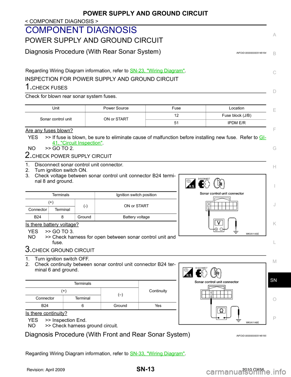
2.CHECK POWER SUPPLY CIRCUIT
1. Disconnect sonar control unit connector.
2. Turn ignition switch ON.
3. Check voltage between sonar control unit connector B24 termi- nal 8 and ground.
Is there battery voltage?
YES >> GO TO 3.
NO >> Check harness for open between sonar control unit and fuse.
3.CHECK GROUND CIRCUIT
1. Turn ignition switch OFF.
2. Check continuity between sonar control unit connector B24 ter- minal 6 and ground.
Is there continuity?
YES >> Inspection End.
NO >> Check harness ground circuit.
Diagnosis Procedure (With Front and Rear Sonar System)INFOID:0000000005146195
Regarding Wiring Diagram information, refer to SN-33, "Wiring Diagram".
UnitPower Source FuseLocation
Sonar control unit ON or START 12
Fuse block (J/B)
51 IPDM E/R
Terminals Ignition switch position
(+) (-) ON or START
Connector Terminal
B24 8 Ground Battery voltage
WKIA1145E
Te r m i n a l s
Continuity
(+)
(–)
Connector Terminal
B24 6 Ground Yes
WKIA1146E
Revision: April 20092010 QX56
Page 3487 of 4210
SN
SONAR SENSOR CIRCUIT INSPECTIONSN-15
< COMPONENT DIAGNOSIS >
C
DE
F
G H
I
J
K L
M B A
O P
SONAR SENSOR CIRCUIT INSPECTION
DescriptionINFOID:0000000005146196
With power and ground supplied to the sonar sensors, the sonar sensors transmit an ultrasonic signal. This
signal is reflected back to the sensor by objec ts large enough and close enough to be detected. The sonar
sensors measure the time from the transmitted signal to the time the signal is reflected back and send this
information to the sonar control unit.
Diagnosis Procedure (With Rear Sonar System)INFOID:0000000005146197
Regarding Wiring Diagram information, refer to SN-23, "Wiring Diagram".
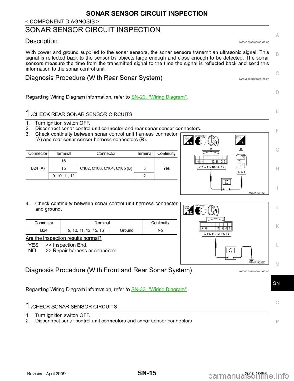
1.CHECK REAR SONAR SENSOR CIRCUITS
1. Turn ignition switch OFF.
2. Disconnect sonar control unit connector and rear sonar sensor connectors.
3. Check continuity between sonar control unit harness connector (A) and rear sonar sensor harness connectors (B).
4. Check continuity between sonar control unit harness connector and ground.
Are the inspection results normal?
YES >> Inspection End.
NO >> Repair harness or connector.
Diagnosis Procedure (With Front and Rear Sonar System)INFOID:0000000005146198
Regarding Wiring Diagram information, refer to SN-33, "Wiring Diagram".
1.CHECK SONAR SENSOR CIRCUITS
1. Turn ignition switch OFF.
2. Disconnect sonar control unit connec tors and sonar sensor connectors.
Connector TerminalConnectorTerminal Continuity
B24 (A) 16
C102, C103, C104, C105 (B) 1
Ye s
15 3
9, 10, 11, 12 2
AWNIA1501ZZ
ConnectorTerminalContinuity
B24 9, 10, 11, 12, 15, 16 Ground No
AWNIA1502ZZ
Revision: April 20092010 QX56
Page 3489 of 4210
SN
SONAR BUZZER CIRCUIT INSPECTIONSN-17
< COMPONENT DIAGNOSIS >
C
DE
F
G H
I
J
K L
M B A
O P
SONAR BUZZER CIRCUIT INSPECTION
DescriptionINFOID:0000000005146199
When the A/T selector lever is not it park or neutral, a stationary object will be detected by the sonar sensors
causing the front or rear sonar buzzer to sound a tone. As the vehicle moves closer to the object, the rate of
the tone will increase. When the object is very cl ose to the vehicle, the tone will sound continuously.
Diagnosis Procedure (With Rear Sonar System)INFOID:0000000005146200
Regarding Wiring Diagram information, refer to SN-23, "Wiring Diagram".
1.CHECK SONAR BUZZER
Refer to SN-18, "
Component Inspection".
Is the inspection result normal?
YES >> GO TO 2.
NO >> Replace sonar buzzer. Refer to SN-51, "
Removal and Installation".
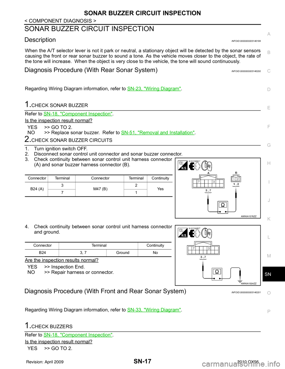
2.CHECK SONAR BUZZER CIRCUITS
1. Turn ignition switch OFF.
2. Disconnect sonar control unit connector and sonar buzzer connector.
3. Check continuity between sonar control unit harness connector (A) and sonar buzzer harness connector (B).
4. Check continuity between sonar control unit harness connector and ground.
Are the inspection results normal?
YES >> Inspection End.
NO >> Repair harness or connector.
Diagnosis Procedure (With Front and Rear Sonar System)INFOID:0000000005146201
Regarding Wiring Diagram information, refer to SN-33, "Wiring Diagram".
1.CHECK BUZZERS
Refer to SN-18, "
Component Inspection".
Is the inspection result normal?
YES >> GO TO 2.
Connector Terminal Connector Terminal Continuity
B24 (A) 3
M47 (B) 2
Ye s
71
AWNIA1576ZZ
Connector TerminalContinuity
B24 3, 7Ground No
AWNIA1504ZZ
Revision: April 20092010 QX56
Page 3491 of 4210
SN
SONAR SYSTEM OFF SWITCH CIRCUIT INSPECTIONSN-19
< COMPONENT DIAGNOSIS >
C
DE
F
G H
I
J
K L
M B A
O P
SONAR SYSTEM OFF SWITCH CIRCUIT INSPECTION
DescriptionINFOID:0000000005146203
The sonar system can be disabled by momentarily pressing the sonar system OFF switch. The sonar system
OFF indicator lamp will be illuminated when the sonar s ystem is OFF. Enabling the sonar system will cause
the sonar system OFF indicator to go out. The indica tor will flash if a malfunction exists in the system.
Diagnosis Procedure (With Rear Sonar System)INFOID:0000000005146204
Regarding Wiring Diagram information, refer to SN-23, "Wiring Diagram".
1.CHECK SONAR SYSTEM OFF SWITCH
Refer to SN-20, "
Component Inspection".
Is the inspection result normal?
YES >> GO TO 2.
NO >> Replace sonar system OFF switch. Refer to IP-14, "
Removal and Installation".
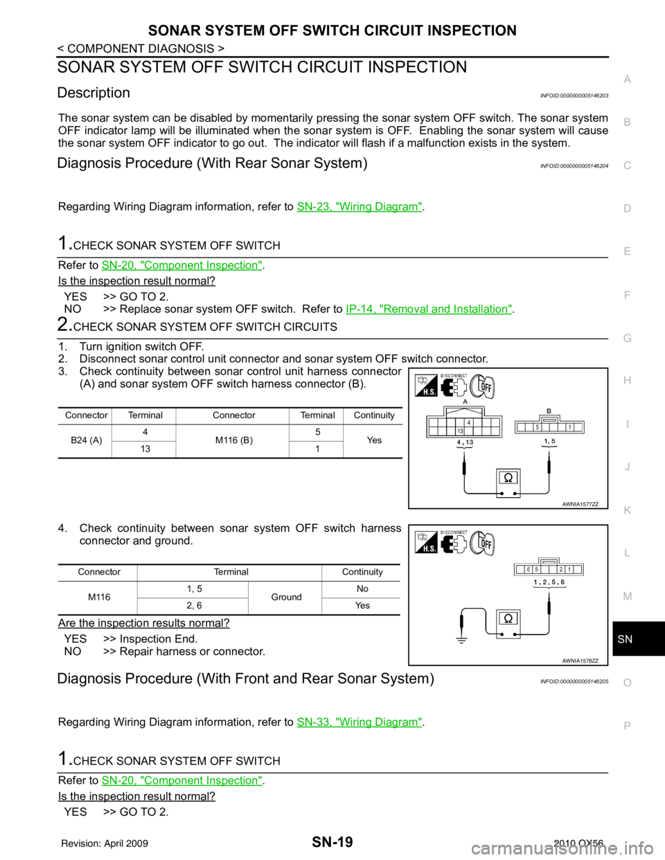
2.CHECK SONAR SYSTEM OFF SWITCH CIRCUITS
1. Turn ignition switch OFF.
2. Disconnect sonar control unit connector and sonar system OFF switch connector.
3. Check continuity between sonar control unit harness connector (A) and sonar system OFF switch harness connector (B).
4. Check continuity between sonar system OFF switch harness connector and ground.
Are the inspection results normal?
YES >> Inspection End.
NO >> Repair harness or connector.
Diagnosis Procedure (With Front and Rear Sonar System)INFOID:0000000005146205
Regarding Wiring Diagram information, refer to SN-33, "Wiring Diagram".
1.CHECK SONAR SYSTEM OFF SWITCH
Refer to SN-20, "
Component Inspection".
Is the inspection result normal?
YES >> GO TO 2.
Connector Terminal Connector Terminal Continuity
B24 (A) 4
M116 (B) 5
Ye s
13 1
AWNIA1577ZZ
ConnectorTerminalContinuity
M116 1, 5
Ground No
2, 6 Yes
AWNIA1578ZZ
Revision: April 20092010 QX56
Page 3495 of 4210
SN
SONAR CONTROL UNIT FOR REAR SONAR SYSTEMSN-23
< ECU DIAGNOSIS >
C
DE
F
G H
I
J
K L
M B A
O P
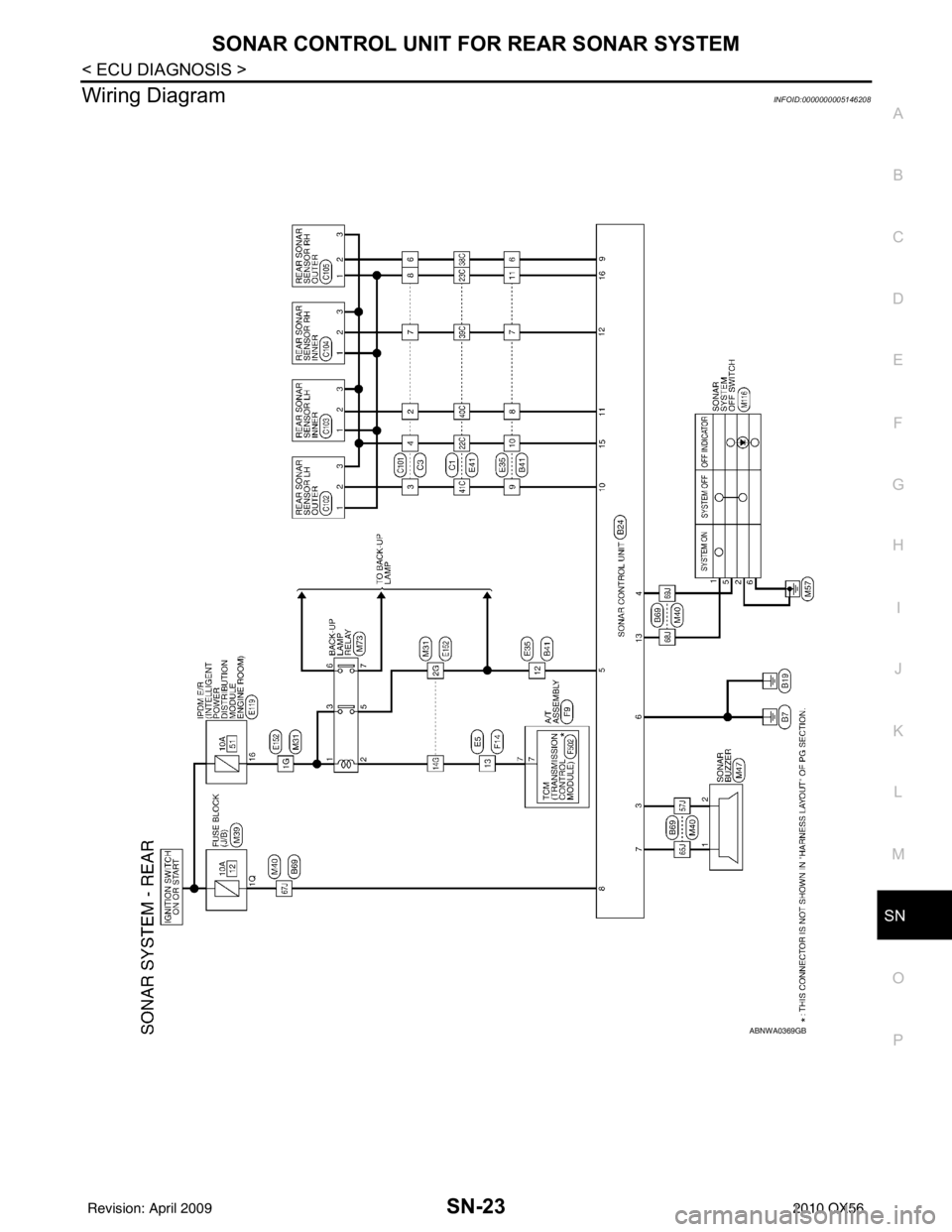
Wiring DiagramINFOID:0000000005146208
ABNWA0369GB
Revision: April 20092010 QX56
Page 3505 of 4210
SN
SONAR CONTROL UNIT FOR FRONT AND REAR SONAR SYSTEMSN-33
< ECU DIAGNOSIS >
C
DE
F
G H
I
J
K L
M B A
O P
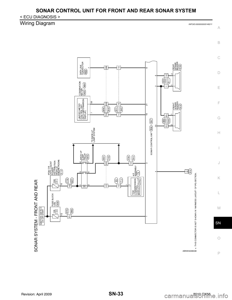
Wiring DiagramINFOID:0000000005146211
ABNWA0385GB
Revision: April 20092010 QX56
Page 3518 of 4210
SN-46
< PRECAUTION >
PRECAUTION
PRECAUTION
PRECAUTION
Precaution for Supplemental Restraint System (SRS) "AIR BAG" and "SEAT BELT
PRE-TENSIONER"
INFOID:0000000005403331
The Supplemental Restraint System such as “A IR BAG” and “SEAT BELT PRE-TENSIONER”, used along
with a front seat belt, helps to reduce the risk or severity of injury to the driver and front passenger for certain
types of collision. This system includes seat belt switch inputs and dual stage front air bag modules. The SRS
system uses the seat belt switches to determine the front air bag deployment, and may only deploy one front
air bag, depending on the severity of a collision and w hether the front occupants are belted or unbelted.
Information necessary to service the system safely is included in the SR and SB section of this Service Man-
ual.
WARNING:
• To avoid rendering the SRS inopera tive, which could increase the risk of personal injury or death in
the event of a collision which would result in air bag inflation, all maintenance must be performed by
an authorized NISSAN/INFINITI dealer.
• Improper maintenance, including in correct removal and installation of the SRS, can lead to personal
injury caused by unintent ional activation of the system. For re moval of Spiral Cable and Air Bag
Module, see the SR section.
• Do not use electrical test equipmen t on any circuit related to the SRS unless instructed to in this
Service Manual. SRS wiring harn esses can be identified by yellow and/or orange harnesses or har-
ness connectors.
PRECAUTIONS WHEN USING POWER TOOLS (AIR OR ELECTRIC) AND HAMMERS
WARNING:
• When working near the Airbag Diagnosis Sensor Unit or other Airbag System sensors with the Igni-
tion ON or engine running, DO NOT use air or electri c power tools or strike near the sensor(s) with a
hammer. Heavy vibration could activate the sensor( s) and deploy the air bag(s), possibly causing
serious injury.
• When using air or electric power tools or hammers , always switch the Ignition OFF, disconnect the
battery, and wait at least 3 minu tes before performing any service.
Precaution Necessary for Steering W heel Rotation After Battery Disconnect
INFOID:0000000005403332
NOTE:
• This Procedure is applied only to models with Intelligent Key system and NATS (NISSAN ANTI-THEFT SYS-
TEM).
• Remove and install all control units after disconnecting both battery cables with the ignition knob in the
″LOCK ″ position.
• Always use CONSULT-III to perform self-diagnosis as a part of each function inspection after finishing work.
If DTC is detected, perform trouble diagnosis according to self-diagnostic results.
For models equipped with the Intelligent Key system and NATS, an electrically controlled steering lock mech-
anism is adopted on the key cylinder.
For this reason, if the battery is disconnected or if the battery is discharged, the steering wheel will lock and
steering wheel rotation will become impossible.
If steering wheel rotation is required when battery pow er is interrupted, follow the procedure below before
starting the repair operation.
OPERATION PROCEDURE
1. Connect both battery cables. NOTE:
Supply power using jumper cables if battery is discharged.
2. Use the Intelligent Key or mechanical key to turn the ignition switch to the ″ACC ″ position. At this time, the
steering lock will be released.
3. Disconnect both battery cables. The steering lock will remain released and the steering wheel can be rotated.
4. Perform the necessary repair operation.
Revision: April 20092010 QX56