2010 INFINITI QX56 mirror
[x] Cancel search: mirrorPage 129 of 4210

DRIVER SEAT CONTROL UNITADP-115
< ECU DIAGNOSIS >
C
DE
F
G H
I
K L
M A
B
ADP
N
O P
TERMINAL LAYOUT
PHYSICAL VALUES
DETENT SW AT selector lever P position
OFF
Other than above ON
STARTER SW Ignition position Cranking
ON
Other than above OFF
SLIDE PULSE Seat sliding Forward
The numeral value decreases
Backward The numeral value increases
Other than above No change to numeral value
RECLN PULSE Seat reclining Forward
The numeral value decreases
Backward The numeral value increases
Other than above No change to numeral value
LIFT FR PULSE Seat lifter (front) Up
The numeral value decreases
Down The numeral value increases
Other than above No change to numeral value
LIFT RR PULSE Seat lifter (rear) Up
The numeral value decreases
Down The numeral value increases
Other than above No change to numeral value
MIR/SEN RH U–D Door mirror (passenger side) Close to peak
3.4
Close to valley 0.6
MIR/SEN RH R–L Door mirror (passenger side) Close to left edge
3.4
Close to right edge 0.6
MIR/SEN LH U–D Door mirror (driver side) Close to peak
3.4
Close to valley 0.6
MIR/SEN LH R–L Door mirror (driver side) Close to left edge
0.6
Close to right edge 3.4
PEDAL SEN Pedal position Forward
0.5
Backward 4.5
Monitor Item
Condition Value/Status
LIIA2449E
Revision: April 20092010 QX56
Page 148 of 4210

ADP-134
< ECU DIAGNOSIS >
DRIVER SEAT CONTROL UNIT
NOTE:
The front seat LH position and pedal adjustment functions (see the following table) operate simultaneously in
the order of priority.
*: In conjunction with sliding the seat, the door mirrors are positioned.
CANCEL OF FAIL-SAFE MODE
The mode is cancelled when the A/T selector lever is shifted to P position from any other position.
DTC IndexINFOID:0000000005147579
*1:
• 0: Current malfunction is present
• 1-39: Displayed if any previous malfunction is present when current condition is normal. The numeral value increases by one at each
IGN ON to OFF cycle from 1 to 39. The counter remains at 39 even if the number of cycles exceeds it. However, the counter is re set
to 1 if any malfunction is detected again, the normal operation is resumed and the ignition switch is turned from OFF to ON. OPERATED PORTION
T2
Seat sliding Approx. 0.1 sec.
Seat reclining Same as above
Seat lifting (Front) Same as above
Seat lifting (Rear) Same as above
Pedal adjust Same as above
Priority Function PriorityFunction
1 Seat sliding, (door mirro r LH/RH)* 4Seat lifter-FR
2 Pedal 5Seat lifter-RR
3 Seat reclining
CONSULT-III
display Timing
*1
Item
Reference page
Current mal-
function Previous mal-
function
CAN COMM CIRCUIT
[U1000] 0
1-39 CAN communication ADP-31
SEAT SLIDE
[B2112]0
1-39 Seat slide motor output ADP-32
SEAT RECLINING
[B2113]0
1-39 Seat reclin ing motor output ADP-33
SEAT LIFTER FRONT
[B2114] 0
1-39 Seat lifting motor front output ADP-36
SEAT LIFTER REAR
[B2115]0
1-39 Seat lifting motor rear output ADP-36
TILT MOTOR
[B2116]0
1-39 Tilt motor output ADP-105
ADJ PEDAL MOTOR
[B2117]0
1-39 Pedal adjusting motor output ADP-36
TILT SENSOR
[B2118]0
1-39 Tilt sensor input ADP-38
ADJ PEDAL SENSOR
[B2120]0
1-39 Pedal adjusting sensor input ADP-36
DETENT SW
[B2126]0
1-39 Park position switch condition ADP-42
UART COMM
[B2128]0
1-39 UART communication ADP-44
Revision: April 20092010 QX56
Page 149 of 4210

AUTOMATIC DRIVE POSITIONER CONTROL UNITADP-135
< ECU DIAGNOSIS >
C
DE
F
G H
I
K L
M A
B
ADP
N
O P
AUTOMATIC DRIVE POSITIONER CONTROL UNIT
Reference ValueINFOID:0000000005147580
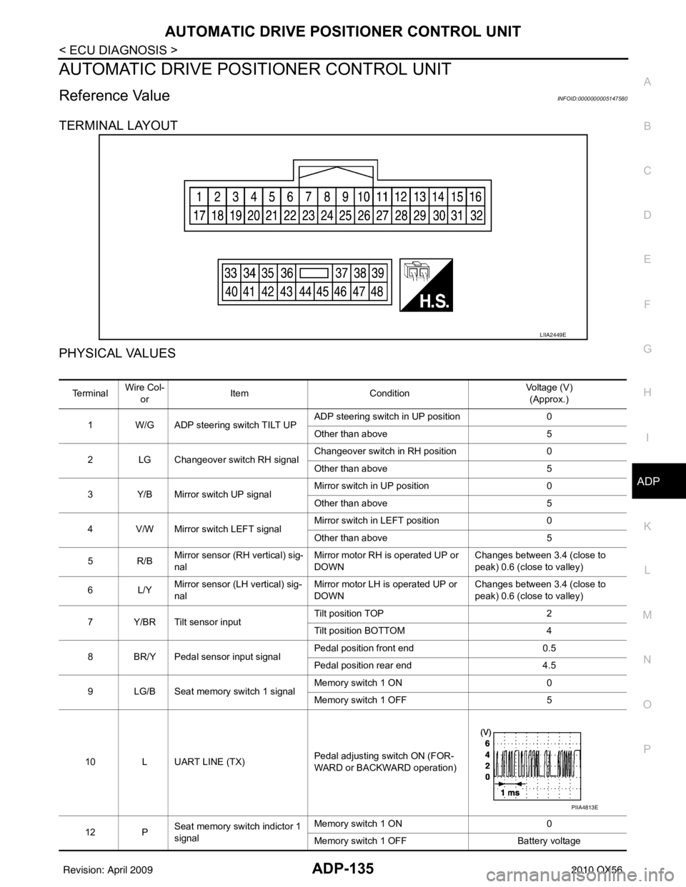
TERMINAL LAYOUT
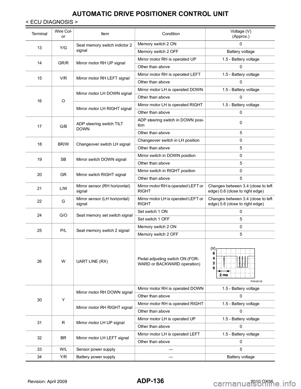
PHYSICAL VALUES
LIIA2449E
Te r m i n a l Wire Col-
or Item
Condition Voltage (V)
(Approx.)
1 W/G ADP steering switch TILT UP ADP steering switch in UP position
0
Other than above 5
2 LG Changeover switch RH signal Changeover switch in RH position
0
Other than above 5
3 Y/B Mirror switch UP signal Mirror switch in UP position
0
Other than above 5
4 V/W Mirror switch LEFT signal Mirror switch in LEFT position
0
Other than above 5
5R/B Mirror sensor (
RH vertical) sig-
nal Mirror motor RH is operated UP or
DOWN Changes between 3.4 (close to
peak) 0.6 (close to valley)
6L/Y Mirror sensor (L
H vertical) sig-
nal Mirror motor LH is operated UP or
DOWN Changes between 3.4 (close to
peak) 0.6 (close to valley)
7 Y/BR Tilt sensor input Tilt position TOP
2
Tilt position BOTTOM 4
8 BR/Y Pedal sensor input signal Pedal position front end
0.5
Pedal position rear end 4.5
9 LG/B Seat memory switch 1 signal Memory switch 1 ON
0
Memory switch 1 OFF 5
10 L UART LINE (TX) Pedal adjusting switch ON (FOR-
WARD or BACKWARD operation)
12 P Seat memory switch indictor 1
signal Memory switch 1 ON
0
Memory switch 1 OFF Battery voltage
PIIA4813E
Revision: April 20092010 QX56
Page 150 of 4210

ADP-136
< ECU DIAGNOSIS >
AUTOMATIC DRIVE POSITIONER CONTROL UNIT
13 Y/GSeat memory switch indictor 2
signal Memory switch 2 ON
0
Memory switch 2 OFF Battery voltage
14 GR/R Mirror motor RH UP signal Mirror motor RH is operated UP
1.5 - Battery voltage
Other than above 0
15 V/R Mirror motor RH LEFT signal Mirror motor RH is operated LEFT
1.5 - Battery voltage
Other than above 0
16 O Mirror motor LH
DOWN signal Mirror motor LH is operated DOWN 1.5 - Battery voltage
Other than above
0
Mirror motor LH RIGHT signal Mirror motor LH is operated RIGHT 1.5 - Battery voltage
Other than above
0
17 G/B ADP steering switch TILT
DOWN ADP steering switch in DOWN posi-
tion
0
Other than above 5
18 BR/W Changeover switch LH signal Changeover switch in LH position
0
Other than above 5
19 SB Mirror switch DOWN signal Mirror switch in DOWN position
0
Other than above 5
20 GR Mirror switch RIGHT signal Mirror switch in RIGHT position
0
Other than above 5
21 L/W Mirror sensor (RH horizontal)
signal Mirror motor RH is operated LEFT or
RIGHT Changes between 3.4 (close to left
edge) 0.6 (close to right edge)
22 G Mirror sensor (LH horizontal)
signal Mirror motor LH is operated LEFT or
RIGHT Changes between 3.4 (close to left
edge) 0.6 (close to right edge)
24 G/O Seat memory set switch signal Set switch 1 ON
0
Set switch 1 OFF 5
25 P/L Seat memory switch 2 signal Memory switch 2 ON
0
Memory switch 2 OFF 5
26 W UART LINE (RX) Pedal adjusting switch ON (FOR-
WARD or BACKWARD operation)
30 Y Mirror motor RH DOWN signal
Mirror motor RH is operated DOWN 1.5 - Battery voltage
Other than above
0
Mirror motor RH RIGHT signal Mirror motor RH is operated RIGHT 1.5 - Battery voltage
Other than above
0
31 R Mirror motor LH UP signal Mirror motor LH is operated UP
1.5 - Battery voltage
Other than above 0
32 BR Mirror motor LH LEFT signal Mirror motor LH is operated LEFT
1.5 - Battery voltage
Other than above 0
33 W/L Sensor power supply —5
34 Y/R Battery power supply —Battery voltage
Te r m i n a l
Wire Col-
or Item
Condition Voltage (V)
(Approx.)
PIIA4814E
Revision: April 20092010 QX56
Page 183 of 4210

ADP SYSTEM SYMPTOMSADP-169
< SYMPTOM DIAGNOSIS >
C
DE
F
G H
I
K L
M A
B
ADP
N
O P
SYMPTOM DIAGNOSIS
ADP SYSTEM SYMPTOMS
Symptom TableINFOID:0000000005147586
NOTE:
Always perform the “Basic Inspection” before perfo rming diagnosis in the following table. Refer to ADP-5,
"Work Flow".
SYMPTOM 1
SYMPTOM 2
SYMPTOM 3
Symptom Diagnosis procedureReference
page
Manual functions (for specific part) do
not operate Sliding operation
Check sliding switch. ADP-50
Reclining operationCheck reclining switch. ADP-53
Lifting operation (front) Check lifting switch (front). ADP-56
Lifting operation (rear) Check lifting switch (rear).ADP-59
Pedal operation1. Check pedal adjusting switch.
ADP-652. Check pedal adjusting sensor.ADP-91
Steering wheel tilt operation Check ADP steering switch ADP-62
Door mirror operation1. Changeover switch.
ADP-702. Mirror switchADP-72
All parts of seatCheck power seat switch ground cir-
cuit. ADP-76
Symptom
Diagnosis procedureReference
page
Memory functions (for specific part) do
not operate Sliding operation
Check sliding sensor. ADP-81
Reclining operationCheck reclining sensor. ADP-83
Lifting operation (front) Check lifting sensor (front). ADP-85
Lifting operation (rear) Check lifting sensor (rear).ADP-87
Pedal operationCheck pedal adjusting sensor. ADP-91
Steering wheel tilt operation Check tilt sensor ADP-89
Door mirror operation Check door mirror sensor. Driver side:
ADP-93Passenger side:
ADP-95
Symptom Diagnosis procedureReference
page
Memory functions and manual func-
tions (for specific part) do not operate Sliding operation
Check sliding motor. ADP-97
Reclining operationCheck reclining motor. ADP-99
Lifting operation (front) Check lifting motor (front). ADP-101
Lifting operation (rear) Check lifting motor (rear).ADP-103
Pedal operationCheck pedal adjusting motor. ADP-107
Steering wheel operation Check tilt motor ADP-105
Door mirror operation Check door mirror motor.ADP-109
Revision: April 20092010 QX56
Page 191 of 4210

DOOR MIRROR REMOTE CONTROL SWITCHADP-177
< ON-VEHICLE REPAIR >
C
DE
F
G H
I
K L
M A
B
ADP
N
O P
DOOR MIRROR REMOTE CONTROL SWITCH
Removal and InstallationINFOID:0000000005147595
The door mirror remote control switch is part of the power window switch assembly. Refer to INT-11, "Removal
and Installation" for removal and installation of door mirror remote control switch.
Revision: April 20092010 QX56
Page 618 of 4210

BODY REPAIRBRM-7
< SERVICE INFORMATION >
C
DE
F
G H
I
J
L
M A
B
BRM
N
O P
Body Exterior Paint ColorINFOID:0000000005147332
M: Metallic; 2S: 2-Coat Solid, 2P: 2-Coat Pearl; 3P: 3-Coat Pearl; t: New Cross Linking Clear Coat
LIIA1437E
Component Color code NAD B30 G10 K11 K12 Q11
Description
Deep
Garnet Lake-
shore
Slate Liquid
Onyx Silver
Graphite Silver
Indulgence Tuscan
Pearl
Clear coat t t t t tt
1 Outside
mirror Body
Chromium
plate Cr2P Cr2P Cr2P Cr2P Cr2P Cr2P
Base Black KH3 KH3 KH3 KH3 KH3 KH3
2 Radiator grille Center and
emblemChromium
plate
Cr2P Cr2P Cr2P Cr2P Cr2P Cr2P
3 Bumpers Fascias Body color NAD B30 G10 K11 K12 Q11
4 Valance BlackKH3 KH3 KH3 KH3 KH3 KH3
5 Running Boards Body Body color NAD B30 G10 K11 K12 Q11
Step pad Black
KH3 KH3 KH3 KH3 KH3 KH3
6 Outside handles Chromium
plate
Cr2P Cr2P Cr2P Cr2P Cr2P Cr2P
B o d y c o l o r N A D B 3 0 G 1 0 K 11 K 1 2 Q 11
7 Side Guard
Molding To p
Chromium
plate Cr2P Cr2P Cr2P Cr2P Cr2P Cr2P
Bottom Body color NAD B30 G10 K11 K12 Q11
8 License plate
finisher Base Body color NAD B30 G10 K11 K12 Q11
Top and bot-
tom trim
Chromium
plate
Cr2P Cr2P Cr2P Cr2P Cr2P Cr2P
9 Cowl top cover Body color NAD B30 G10 K11 K12 Q11
10 Rear spoiler Body color NAD B30 G10 K11 K12 Q11
Revision: April 20092010 QX56
Page 789 of 4210

DEF-1
DRIVER CONTROLS
C
DE
F
G H
I
J
K
M
SECTION DEF
A
B
DEF
N
O P
CONTENTS
DEFOGGER
BASIC INSPECTION ....... .............................3
DIAGNOSIS AND REPAIR WORKFLOW ..... .....3
Repair Work Flow ................................................ ......3
FUNCTION DIAGNOSIS ...............................4
REAR WINDOW DEFOGGER SYSTEM ........ .....4
System Diagram .................................................. ......4
System Description ...................................................4
Component Parts Location ........................................5
Component Description .............................................5
DIAGNOSIS SYSTEM (BCM) .............................6
COMMON ITEM ..................................................... ......6
COMMON ITEM : CONSULT-III Function (BCM -
COMMON ITEM) .......................................................
6
REAR WINDOW DEFOGGER ............................... ......6
REAR WINDOW DEFOGGER : CONSULT-III
Function (BCM - REAR DEFOGGER) ......................
7
COMPONENT DIAGNOSIS ..........................8
REAR WINDOW DEFOGGER SWITCH ........ .....8
Description .......................................................... ......8
Component Function Check ......................................8
Diagnosis Procedure .................................................8
REAR WINDOW DEFOGGER RELAY ...............9
Description .......................................................... ......9
Component Function Check ......................................9
Diagnosis Procedure .................................................9
REAR WINDOW DEFOGGER POWER SUP-
PLY AND GROUND CIRCUIT ............................
10
Description .......................................................... ....10
Component Function Check ....................................10
Diagnosis Procedure ...............................................10
Component Inspection ............................................11
DOOR MIRROR DEFOGGER LH ..................
....12
Description ........................................................... ....12
Component Function Check ....................................12
Diagnosis Procedure ...............................................12
Component Inspection .............................................13
DOOR MIRROR DEFOGGER RH .....................15
Description ...............................................................15
Component Function Check ....................................15
Diagnosis Procedure ...............................................15
Component Inspection .............................................16
ECU DIAGNOSIS .........................................18
BCM (BODY CONTROL MODULE) .................18
Reference Value .................................................. ....18
Terminal Layout .......................................................21
Physical Values ................................................... ....21
Wiring Diagram ........................................................27
Fail Safe ..................................................................34
DTC Inspection Priority Chart ...............................35
DTC Index ...............................................................35
SYMPTOM DIAGNOSIS ..............................37
REAR WINDOW DEFOGGER AND DOOR
MIRROR DEFOGGER DO NOT OPERATE. ....
37
Diagnosis Procedure ........................................... ....37
REAR WINDOW DEFOGGER DOES NOT
OPERATE BUT BOTH OF DOOR MIRROR
DEFOGGER OPERATE. ...................................
38
Diagnosis Procedure ...............................................38
BOTH DOORS MIRROR DEFOGGER DON’T
OPERATE BUT REAR WINDOW DEFOG-
GER OPERATES ..............................................
39
Diagnosis Procedure ...............................................39
DRIVER SIDE DOOR MIRROR DEFOGGER
DOES NOT OPERATE. .....................................
40
Diagnosis Procedure ...............................................40
Revision: April 20092010 QX56