Page 2772 of 4210

MWI-10
< FUNCTION DIAGNOSIS >
METER SYSTEM
TACHOMETER : System Description
INFOID:0000000005146035
The tachometer indicates engine speed in revolutions per minute (rpm).
The ECM provides an engine speed signal to the co mbination meter via CAN communication lines.
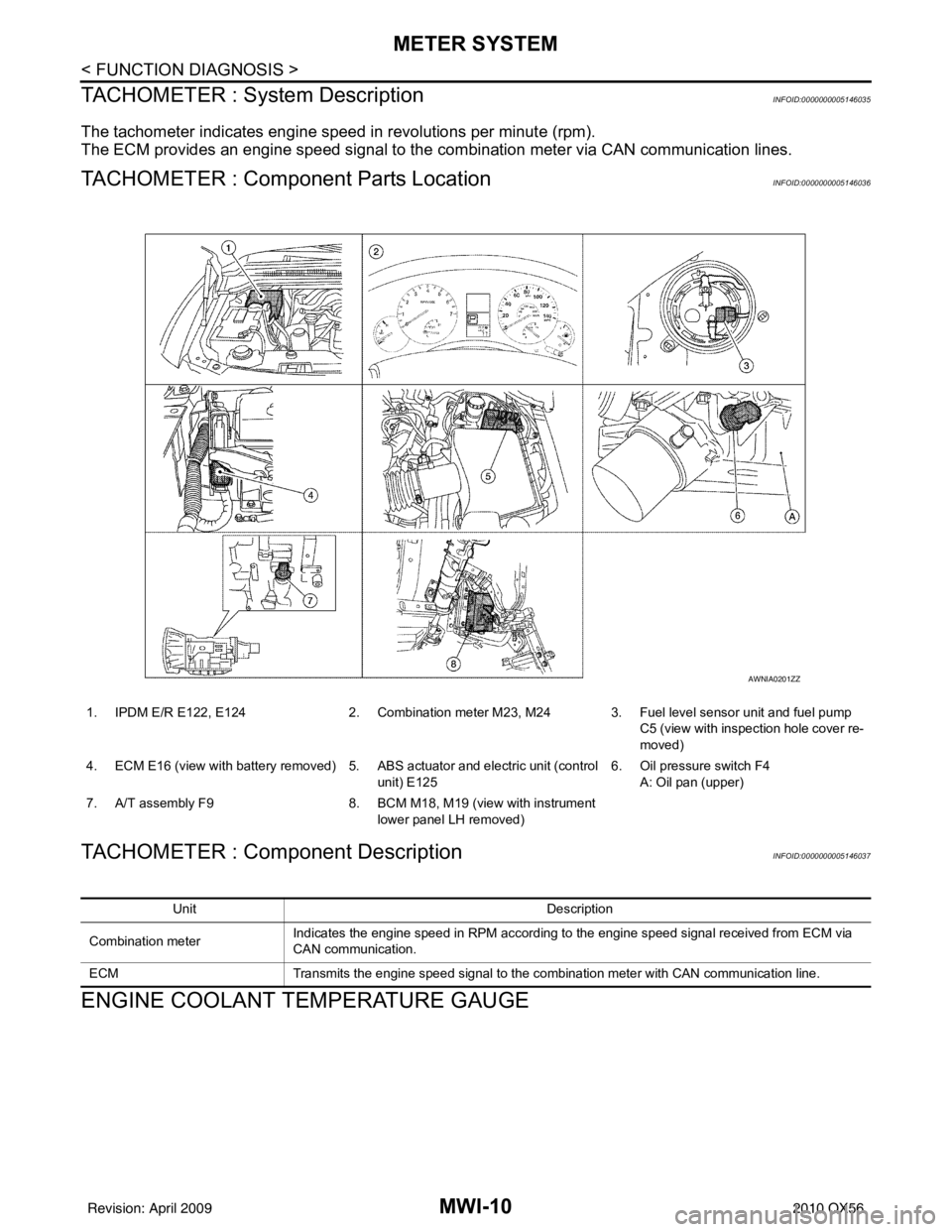
TACHOMETER : Component Parts LocationINFOID:0000000005146036
TACHOMETER : Component DescriptionINFOID:0000000005146037
ENGINE COOLANT TEMPERATURE GAUGE
1. IPDM E/R E122, E1242. Combination meter M23, M24 3. Fuel level sensor unit and fuel pump
C5 (view with inspection hole cover re-
moved)
4. ECM E16 (view with battery removed) 5. ABS actuator and electric unit (control
unit) E125 6. Oil pressure switch F4
A: Oil pan (upper)
7. A/T assembly F9 8. BCM M18, M19 (view with instrument
lower panel LH removed)
AWNIA0201ZZ
Unit Description
Combination meter Indicates the engine speed in RPM according to the engine speed signal received from ECM via
CAN communication.
ECM Transmits the engine speed signal to the combination meter with CAN communication line.
Revision: April 20092010 QX56
Page 2773 of 4210
MWI
METER SYSTEMMWI-11
< FUNCTION DIAGNOSIS >
C
DE
F
G H
I
J
K L
M B A
O P
ENGINE COOLANT TEMPERATURE GAUGE : System DiagramINFOID:0000000005146038
ENGINE COOLANT TEMPERATURE GAUGE : System DescriptionINFOID:0000000005146039
The engine coolant temperature gauge indicates the engine coolant temperature.
The ECM provides an engine coolant temperature signal to the combination meter via CAN communication
lines.
ENGINE COOLANT TEMPERATURE GA UGE : Component Parts Location
INFOID:0000000005146040
SKIB6905E
1. IPDM E/R E122, E124 2. Combination meter M23, M24 3. Fuel level sensor unit and fuel pump
C5 (view with inspection hole cover re-
moved)
4. ECM E16 (view with battery removed) 5. ABS actuator and electric unit (control unit) E1256. Oil pressure switch F4
A: Oil pan (upper)
7. A/T assembly F9 8. BCM M18, M19 (view with instrument
lower panel LH removed)
AWNIA0201ZZ
Revision: April 20092010 QX56
Page 2774 of 4210
MWI-12
< FUNCTION DIAGNOSIS >
METER SYSTEM
ENGINE COOLANT TEMPERATURE GAUGE : Component Description
INFOID:0000000005146041
FUEL GAUGE
FUEL GAUGE : System DiagramINFOID:0000000005146042
FUEL GAUGE : System DescriptionINFOID:0000000005146043
The fuel gauge indicates the approximate fuel level in the fuel tank.
The fuel gauge is regulated by the unified meter control unit and a variable resistor signal supplied by the fuel
level sensor unit.
FUEL GAUGE : Compone nt Parts LocationINFOID:0000000005146044
Unit Description
Combination meter Indicates the engine coolant temperature according to the engine coolant temperature signal re-
ceived from ECM via CAN communication.
ECM Transmits the engine coolant temperature signal to the combination meter via CAN communication.
AWNIA0004GB
AWNIA0201ZZ
Revision: April 20092010 QX56
Page 3190 of 4210

PRECAUTIONSRSU-3
< PRECAUTION >
C
DF
G H
I
J
K L
M A
B
RSU
N
O P
5. When the repair work is completed, return the ignition switch to the ″LOCK ″ position before connecting
the battery cables. (At this time, the steering lock mechanism will engage.)
6. Perform a self-diagnosis check of al l control units using CONSULT-III.
Precaution for Rear SuspensionINFOID:0000000005148126
• When installing the rubber bushings, the final tightening must be done under unladen condition and with the
tires on level ground. Oil will shorten the life of the rubber bushings, so wipe off any spilled oil immediately.
• Unladen condition means the fuel tank, engine coolant and lubricants are at the full specification. The spare
tire, jack, hand tools, and mats are in their designated positions.
• After installing suspension components, check the wheel alignment.
• Caulking nuts are not reusable. Always use new caulking nuts for installation. New caulking nuts are pre- oiled, do not apply any additional lubrication.
Revision: April 20092010 QX56
Page 3193 of 4210

RSU-6
< ON-VEHICLE MAINTENANCE >
REAR SUSPENSION ASSEMBLY
ON-VEHICLE MAINTENANCE
REAR SUSPENSION ASSEMBLY
On-Vehicle Inspection and ServiceINFOID:0000000005148129
Check all of the component mountings for any excessive looseness, or back lash. Check the components for
any excessive wear, damage, or abnormal conditions. Repair or replace the components as necessary.
SHOCK ABSORBER INSPECTION
• Check the shock absorbers for any air leaks or damage, and replace as necessary.
• Check the hoses for any air leaks or damage, and replace as necessary.
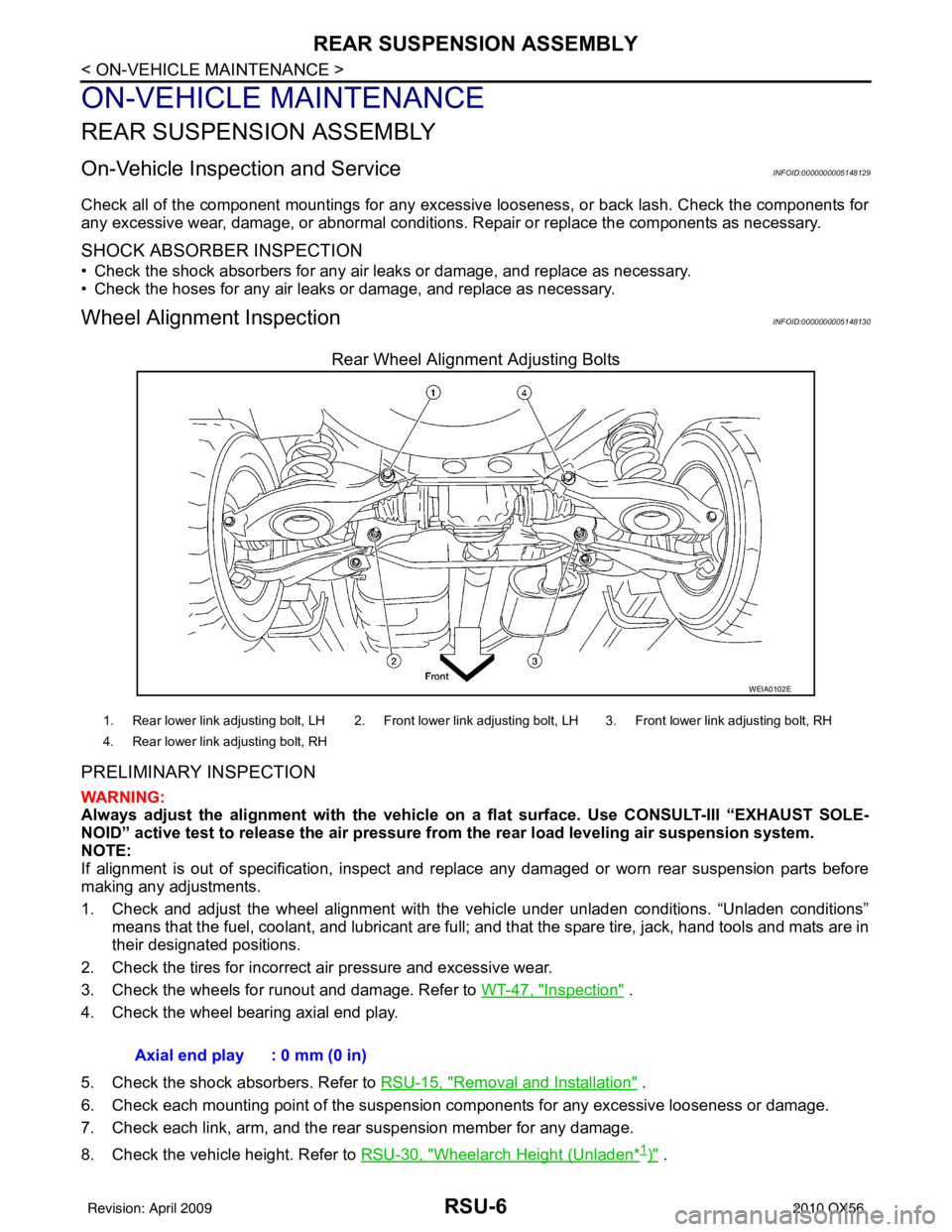
Wheel Alignment InspectionINFOID:0000000005148130
Rear Wheel Alignment Adjusting Bolts
PRELIMINARY INSPECTION
WARNING:
Always adjust the alignment with the vehicle on a flat surface. Use CONSULT-III “EXHAUST SOLE-
NOID” active test to release the air pressure from the rear load leveling air suspension system.
NOTE:
If alignment is out of specificat ion, inspect and replace any damaged or worn rear suspension parts before
making any adjustments.
1. Check and adjust the wheel alignment with the vehicle under unladen conditions. “Unladen conditions”
means that the fuel, coolant, and lubricant are full; and that the spare tire, jack, hand tools and mats are in
their designated positions.
2. Check the tires for incorrect air pressure and excessive wear.
3. Check the wheels for runout and damage. Refer to WT-47, "
Inspection" .
4. Check the wheel bearing axial end play.
5. Check the shock absorbers. Refer to RSU-15, "
Removal and Installation" .
6. Check each mounting point of the suspension components for any excessive looseness or damage.
7. Check each link, arm, and the rear suspension member for any damage.
8. Check the vehicle height. Refer to RSU-30, "
Wheelarch Height (Unladen*1)" .
WEIA0102E
1. Rear lower link adjusting bolt, LH 2. Front lower link adjusting bolt, LH 3. Front lower link adjusting bolt, RH
4. Rear lower link adjusting bolt, RH
Axial end play : 0 mm (0 in)
Revision: April 20092010 QX56
Page 3217 of 4210
RSU-30
< SERVICE DATA AND SPECIFICATIONS (SDS)
SERVICE DATA AND SPECIFICATIONS (SDS)
Wheelarch Height (Unladen*
1)INFOID:0000000005148144
Unit: mm (in)
*1: Fuel, engine coolant and engine oil full. Spare tire, jack, hand tools and mats in designated positions.
*2: Verify the vehicle height. If vehicle height is not within ± 10 mm (0.39 in) of the specification, perform the control unit initialization pro-
cedure. Refer to RSU-26, "
Initialization Procedure" .
Suspension type
Air leveling*
2
Applied model2WD4WD
Front wheelarch height (Hf) 920
(36.22) 937
(36.89)
Rear wheelarch height (Hr) 917
(36.10) 937
(36.89)
LEIA0085E
Revision: April 20092010 QX56
Page 3272 of 4210

SCS-40
< PRECAUTION >
PRECAUTIONS
PRECAUTION
PRECAUTIONS
Precaution for Supplemental Restraint System (SRS) "AIR BAG" and "SEAT BELT
PRE-TENSIONER"
INFOID:0000000005383225
The Supplemental Restraint System such as “A IR BAG” and “SEAT BELT PRE-TENSIONER”, used along
with a front seat belt, helps to reduce the risk or severity of injury to the driver and front passenger for certain
types of collision. This system includes seat belt switch inputs and dual stage front air bag modules. The SRS
system uses the seat belt switches to determine the front air bag deployment, and may only deploy one front
air bag, depending on the severity of a collision and w hether the front occupants are belted or unbelted.
Information necessary to service the system safely is included in the SR and SB section of this Service Man-
ual.
WARNING:
• To avoid rendering the SRS inopera tive, which could increase the risk of personal injury or death in
the event of a collision which would result in air bag inflation, all maintenance must be performed by
an authorized NISSAN/INFINITI dealer.
• Improper maintenance, including in correct removal and installation of the SRS, can lead to personal
injury caused by unintent ional activation of the system. For re moval of Spiral Cable and Air Bag
Module, see the SR section.
• Do not use electrical test equipmen t on any circuit related to the SRS unless instructed to in this
Service Manual. SRS wiring harn esses can be identified by yellow and/or orange harnesses or har-
ness connectors.
PRECAUTIONS WHEN USING POWER TOOLS (AIR OR ELECTRIC) AND HAMMERS
WARNING:
• When working near the Airbag Diagnosis Sensor Unit or other Airbag System sensors with the Igni-
tion ON or engine running, DO NOT use air or electri c power tools or strike near the sensor(s) with a
hammer. Heavy vibration could activate the sensor( s) and deploy the air bag(s), possibly causing
serious injury.
• When using air or electric power tools or hammers , always switch the Ignition OFF, disconnect the
battery, and wait at least 3 minu tes before performing any service.
Precaution for Rear SuspensionINFOID:0000000005148201
• When installing the rubber bushings, the final ti ghtening must be done under unladen condition and with the
tires on level ground. Oil will shorten the life of the r ubber bushings, so wipe off any spilled oil immediately.
• Unladen condition means the fuel tank, engine coolant and lubricants are at the full specification. The spare tire, jack, hand tools, and mats are in their designated positions.
• After installing suspension components, check the wheel alignment.
• Caulking nuts are not reusable. Always use new caulking nuts for installation. New caulking nuts are pre-
oiled, do not apply any additional lubrication.
Revision: April 20092010 QX56