2010 INFINITI QX56 coolant level
[x] Cancel search: coolant levelPage 1822 of 4210
![INFINITI QX56 2010 Factory Service Manual ECM
EC-469
< ECU DIAGNOSIS > [VK56DE]
C
D
E
F
G H
I
J
K L
M A
EC
NP
O
• Sea level
• Flat road
• Ambient air temperature: 20 - 30
°C (68 - 86 °F)
• Diagnosis is performed as quickly as possib INFINITI QX56 2010 Factory Service Manual ECM
EC-469
< ECU DIAGNOSIS > [VK56DE]
C
D
E
F
G H
I
J
K L
M A
EC
NP
O
• Sea level
• Flat road
• Ambient air temperature: 20 - 30
°C (68 - 86 °F)
• Diagnosis is performed as quickly as possib](/manual-img/42/57032/w960_57032-1821.png)
ECM
EC-469
< ECU DIAGNOSIS > [VK56DE]
C
D
E
F
G H
I
J
K L
M A
EC
NP
O
• Sea level
• Flat road
• Ambient air temperature: 20 - 30
°C (68 - 86 °F)
• Diagnosis is performed as quickly as possible under normal conditions. Under different conditions [For example: ambient air temperature other than 20 - 30 °C (68 - 86° F)], diagno-
sis may also be performed.
Pattern 1:
• The engine is started at the engine coolant temperature of −10 to 35 °C (14 to 95 °F)
(where the voltage between the ECM terminal 73 and ground is 3.0 - 4.3V).
• The engine must be operated at idle speed until the engine coolant temperature is greater than 70 °C
(158° F) (where the voltage between the ECM te rminal 73 and ground is lower than 1.4V).
• The engine is started at the fuel tank temperature of warmer than 0 °C (32° F) (where the voltage
between the ECM terminal 107 and ground is less than 4.1V).
Pattern 2:
• When steady-state driving is performed again even afte r it is interrupted, each diagnosis can be conducted.
In this case, the time required for diagnosis may be extended.
Pattern 3:
• Operate vehicle following the driving pattern shown in the figure.
• Release the accelerator pedal during decelerating vehicle speed from 90 km/h (56 MPH) to 0 km/h (0 MPH).
Pattern 4:
• The accelerator pedal must be held very steady during steady- state driving.
• If the accelerator pedal is moved, the test must be conducted all over again.
*1: Depress the accelerator pedal until vehicle speed is 90 km/h (56
MPH), then release the accelerator pedal and keep it released for
more than 10 seconds. Depress the accelerator pedal until vehicle
speed is 90 km/h (56 MPH) again.
*2: Checking the vehicle speed with GST is advised.
Suggested Transmi ssion Gear Position
Set the selector lever in the D position with the overdrive switch turned ON.
TEST VALUE AND TEST LIMIT
The following is the information specified in Service $06 of SAE J1979.
The test value is a parameter used to determine whether a system/circuit diagnostic test is OK or NG while
being monitored by the ECM during self-diagnosis. The test limit is a reference value which is specified as the
maximum or minimum value and is compared with the test value being monitored.
These data (test value and test limit) are specified by On Boad Monitor ID(OBDMID), Test ID (TID), Unit and
Scaling ID and can be displayed on the GST screen.
The items of the test value and test limit will be disp layed with GST screen which items are provided by the
ECM. (eg., if the bank 2 is not applied on this v ehicle, only the items of the bank 1 is displayed)
PBIB2244E
Revision: April 20092010 QX56
Page 1833 of 4210
![INFINITI QX56 2010 Factory Service Manual EC-480
< SYMPTOM DIAGNOSIS >[VK56DE]
ENGINE CONTROL SYSTEM SYMPTOMS
1 - 6: The numbers refer to the order of inspection.Exhaust Exhaust manifold/Tube/Muffler/
Gasket 55555 55 5EM-30
,
EX-
5Three way INFINITI QX56 2010 Factory Service Manual EC-480
< SYMPTOM DIAGNOSIS >[VK56DE]
ENGINE CONTROL SYSTEM SYMPTOMS
1 - 6: The numbers refer to the order of inspection.Exhaust Exhaust manifold/Tube/Muffler/
Gasket 55555 55 5EM-30
,
EX-
5Three way](/manual-img/42/57032/w960_57032-1832.png)
EC-480
< SYMPTOM DIAGNOSIS >[VK56DE]
ENGINE CONTROL SYSTEM SYMPTOMS
1 - 6: The numbers refer to the order of inspection.Exhaust Exhaust manifold/Tube/Muffler/
Gasket 55555 55 5EM-30
,
EX-
5Three way catalyst
Lubrica-
tion Oil pan/Oil strainer/Oil pump/Oil
filter/Oil gallery/Oil cooler
55555 55 5EM-33
,
LU-
14 , LU-11 ,
LU-12
Oil level (Low)/Filthy oil LU-8, "In-
spection"
Cooling Radiator/Hose/Radiator filler cap
55555 55 45 CO-15
Thermostat
5CO-22
Water pump CO-20
Water galleryCO-6
Cooling fan5CO-18,
CO-
19
Coolant level (Low)/Contaminat-
ed coolant 5
CO-10
IVIS (INFINITI Vehicle Immobilizer System —
NATS) 11
SEC-9
SYMPTOM
Reference
page
HARD/NO START/RESTART (EXCP. HA)
ENGINE STALL
HESITATION/SURGING/FLAT SPOT
SPARK KNOCK/DETONATION
LACK OF POWER/POOR ACCELERATION
HIGH IDLE/LOW IDLE
ROUGH IDLE/HUNTING
IDLING VIBRATION
SLOW/NO RETURN TO IDLE
OVERHEATS/WATER TEMPERATURE HIGH
EXCESSIVE FUEL CONSUMPTION
EXCESSIVE OIL CONSUMPTION
BATTERY DEAD (UNDER CHARGE)
Warranty symptom code AA AB AC AD AE AF AG AH AJ AK AL AM HA
Revision: April 20092010 QX56
Page 1880 of 4210
INTAKE MANIFOLDEM-29
< ON-VEHICLE REPAIR >
C
DE
F
G H
I
J
K L
M A
EM
NP
O
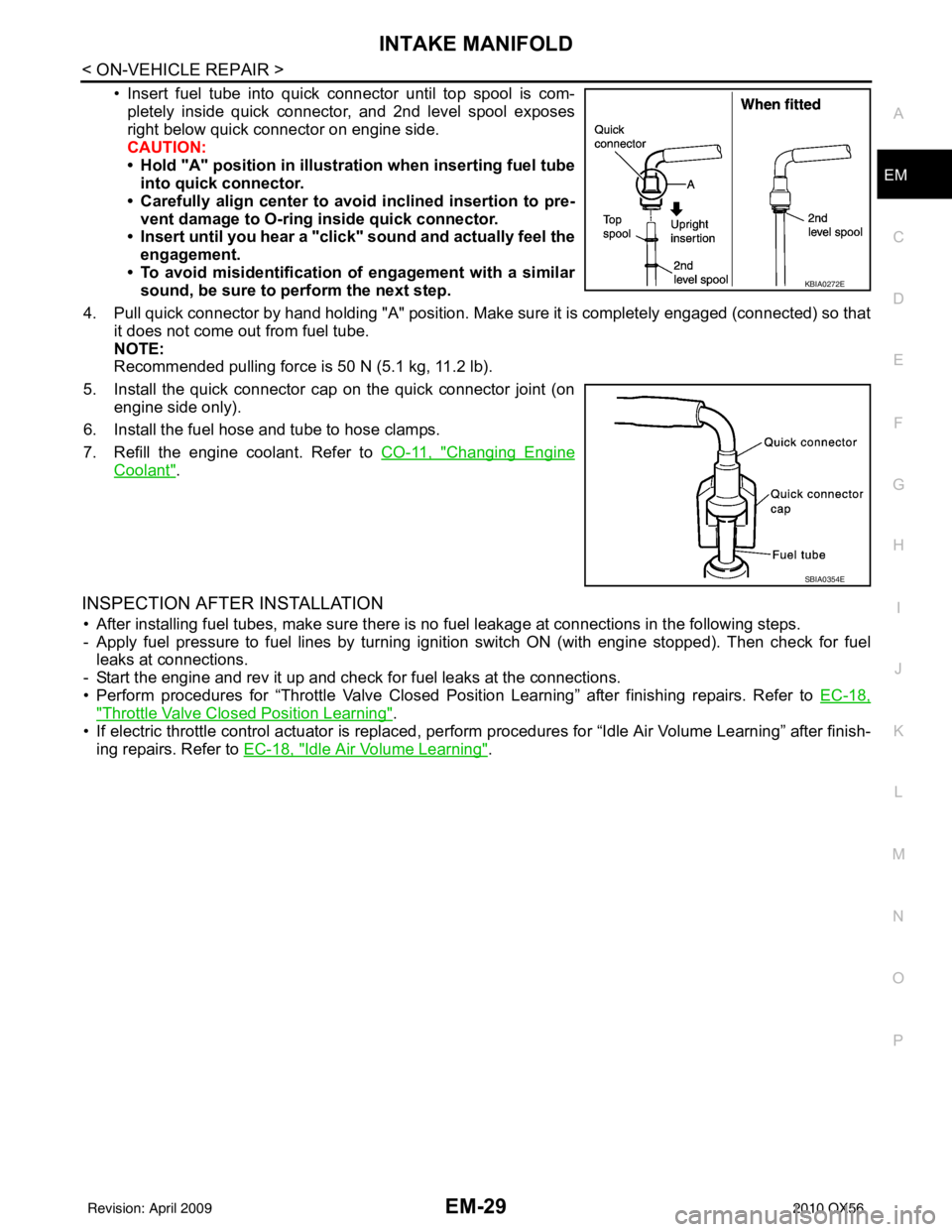
• Insert fuel tube into quick connector until top spool is com-
pletely inside quick connector, and 2nd level spool exposes
right below quick connector on engine side.
CAUTION:
• Hold "A" position in illustration when inserting fuel tubeinto quick connector.
• Carefully align center to avoid inclined insertion to pre-
vent damage to O-ring inside quick connector.
• Insert until you hear a "click" sound and actually feel the
engagement.
• To avoid misidentification of engagement with a similar sound, be sure to perform the next step.
4. Pull quick connector by hand holding "A" position. Make sure it is completely engaged (connected) so that it does not come out from fuel tube.
NOTE:
Recommended pulling force is 50 N (5.1 kg, 11.2 lb).
5. Install the quick connector cap on the quick connector joint (on engine side only).
6. Install the fuel hose and tube to hose clamps.
7. Refill the engine coolant. Refer to CO-11, "
Changing Engine
Coolant".
INSPECTION AFTER INSTALLATION
• After installing fuel tubes, make sure there is no fuel leakage at connections in the following steps.
- Apply fuel pressure to fuel lines by turning ignition switch ON (with engine stopped). Then check for fuel leaks at connections.
- Start the engine and rev it up and check for fuel leaks at the connections.
• Perform procedures for “Throttle Valve Closed Position Learning” after finishing repairs. Refer to EC-18,
"Throttle Valve Closed Position Learning".
• If electric throttle control actuator is replaced, per form procedures for “Idle Air Volume Learning” after finish-
ing repairs. Refer to EC-18, "
Idle Air Volume Learning".
KBIA0272E
SBIA0354E
Revision: April 20092010 QX56
Page 1903 of 4210
EM-52
< ON-VEHICLE REPAIR >
TIMING CHAIN
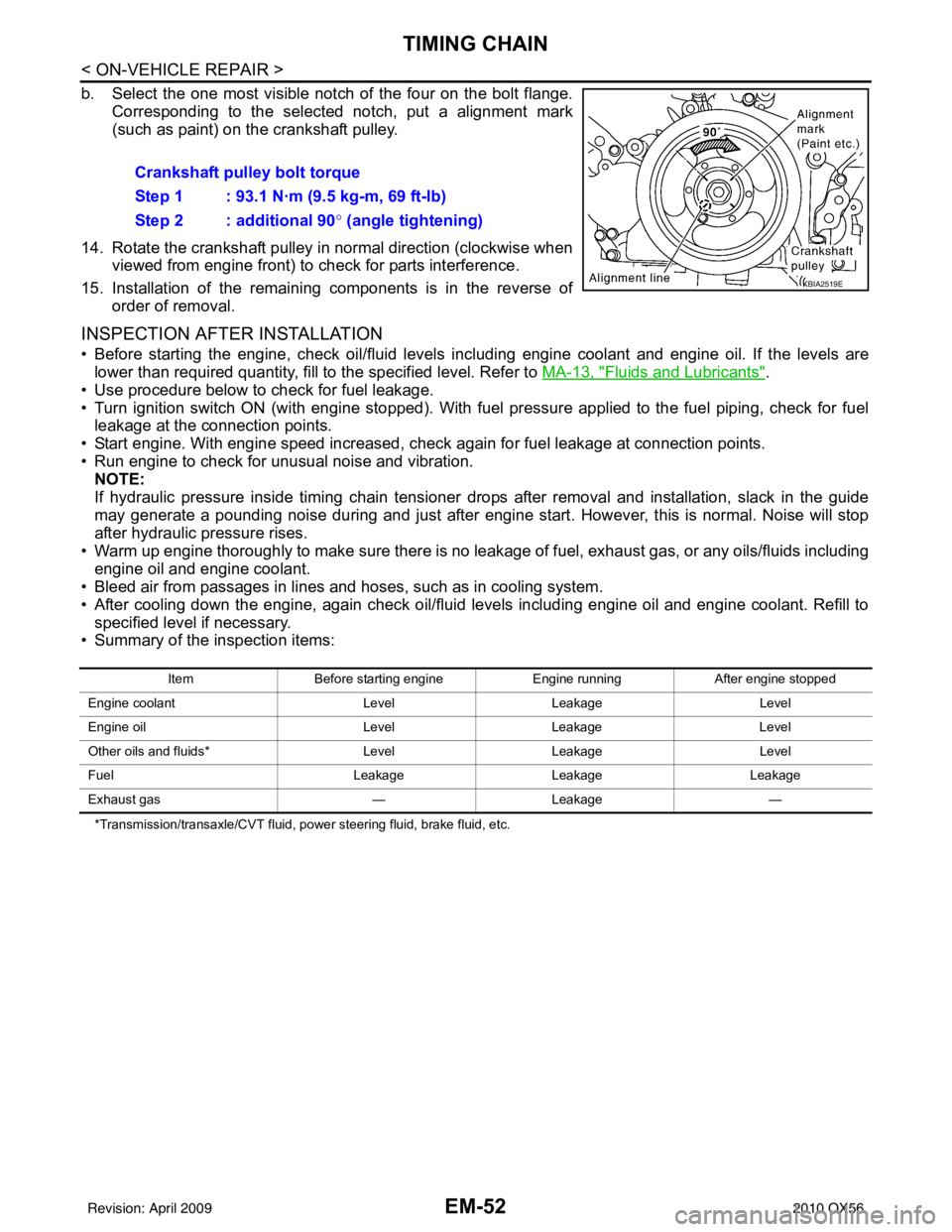
b. Select the one most visible notch of the four on the bolt flange.Corresponding to the selected notch, put a alignment mark
(such as paint) on the crankshaft pulley.
14. Rotate the crankshaft pulley in normal direction (clockwise when viewed from engine front) to check for parts interference.
15. Installation of the remaining components is in the reverse of order of removal.
INSPECTION AFTER INSTALLATION
• Before starting the engine, check oil/fluid levels in cluding engine coolant and engine oil. If the levels are
lower than required quantity, fill to the specified level. Refer to MA-13, "
Fluids and Lubricants".
• Use procedure below to check for fuel leakage.
• Turn ignition switch ON (with engine stopped). With fuel pressure applied to the fuel piping, check for fuel leakage at the connection points.
• Start engine. With engine speed increased, che ck again for fuel leakage at connection points.
• Run engine to check for unusual noise and vibration. NOTE:
If hydraulic pressure inside timing chain tensioner drops after removal and installation, slack in the guide
may generate a pounding noise during and just after engine start. However, this is normal. Noise will stop
after hydraulic pressure rises.
• Warm up engine thoroughly to make sure there is no leakage of fuel, exhaust gas, or any oils/fluids including engine oil and engine coolant.
• Bleed air from passages in lines and hoses, such as in cooling system.
• After cooling down the engine, again check oil/fluid levels including engine oil and engine coolant. Refill to
specified level if necessary.
• Summary of the inspection items:
*Transmission/transaxle/CVT fluid, power steering fluid, brake fluid, etc.
Crankshaft pulley bolt torque
Step 1 : 93.1 N·m (9.5 kg-m, 69 ft-lb)
Step 2 : additional 90 ° (angle tightening)
KBIA2519E
Item Before starting engine Engine runningAfter engine stopped
Engine coolant LevelLeakage Level
Engine oil LevelLeakage Level
Other oils and fluids* LevelLeakage Level
Fuel LeakageLeakageLeakage
Exhaust gas —Leakage —
Revision: April 20092010 QX56
Page 1920 of 4210
CYLINDER HEADEM-69
< ON-VEHICLE REPAIR >
C
DE
F
G H
I
J
K L
M A
EM
NP
O
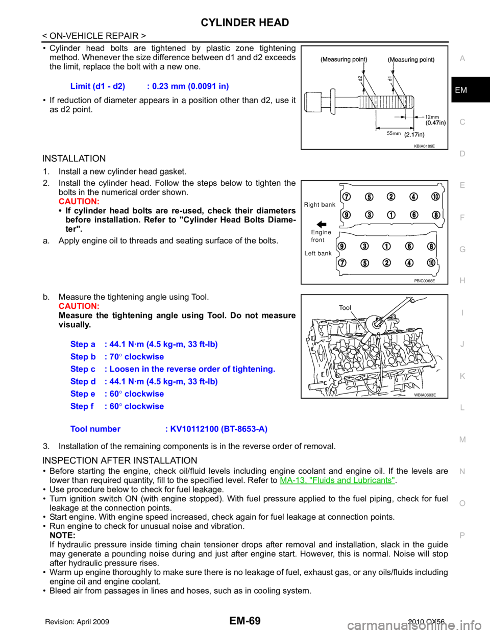
• Cylinder head bolts are tightened by plastic zone tightening
method. Whenever the size difference between d1 and d2 exceeds
the limit, replace the bolt with a new one.
• If reduction of diameter appears in a position other than d2, use it as d2 point.
INSTALLATION
1. Install a new cylinder head gasket.
2. Install the cylinder head. Follow the steps below to tighten the bolts in the numerical order shown.
CAUTION:
• If cylinder head bolts are re-used, check their diameters
before installation. Refer to "Cylinder Head Bolts Diame-
ter".
a. Apply engine oil to threads and seating surface of the bolts.
b. Measure the tightening angle using Tool. CAUTION:
Measure the tightening angl e using Tool. Do not measure
visually.
3. Installation of the remaining components is in the reverse order of removal.
INSPECTION AFTER INSTALLATION
• Before starting the engine, check oil/fluid levels including engine coolant and engine oil. If the levels are lower than required quantity, fill to the specified level. Refer to MA-13, "
Fluids and Lubricants".
• Use procedure below to check for fuel leakage.
• Turn ignition switch ON (with engine stopped). With fuel pressure applied to the fuel piping, check for fuel
leakage at the connection points.
• Start engine. With engine speed increased, check again for fuel leakage at connection points.
• Run engine to check for unusual noise and vibration.
NOTE:
If hydraulic pressure inside timing chain tensioner drops after removal and installation, slack in the guide
may generate a pounding noise during and just after engine start. However, this is normal. Noise will stop
after hydraulic pressure rises.
• Warm up engine thoroughly to make sure there is no leakage of fuel, exhaust gas, or any oils/fluids including
engine oil and engine coolant.
• Bleed air from passages in lines and hoses, such as in cooling system. Limit (d1 - d2) : 0.23 mm (0.0091 in)
KBIA0189E
PBIC0068E
Step a : 44.1 N·m (4.5 kg-m, 33 ft-lb)
Step b : 70°
clockwise
Step c : Loosen in the reverse order of tightening.
Step d : 44.1 N·m (4.5 kg-m, 33 ft-lb)
Step e : 60 ° clockwise
Step f : 60° clockwise
Tool number : KV10112100 (BT-8653-A)
WBIA0603E
Revision: April 20092010 QX56
Page 1921 of 4210
EM-70
< ON-VEHICLE REPAIR >
CYLINDER HEAD
• After cooling down the engine, again check oil/fluid levels including engine oil and engine coolant. Refill tospecified level if necessary.
• Summary of the inspection items:
*Transmission/transaxle/CVT fluid, power steering fluid, brake fluid, etc.
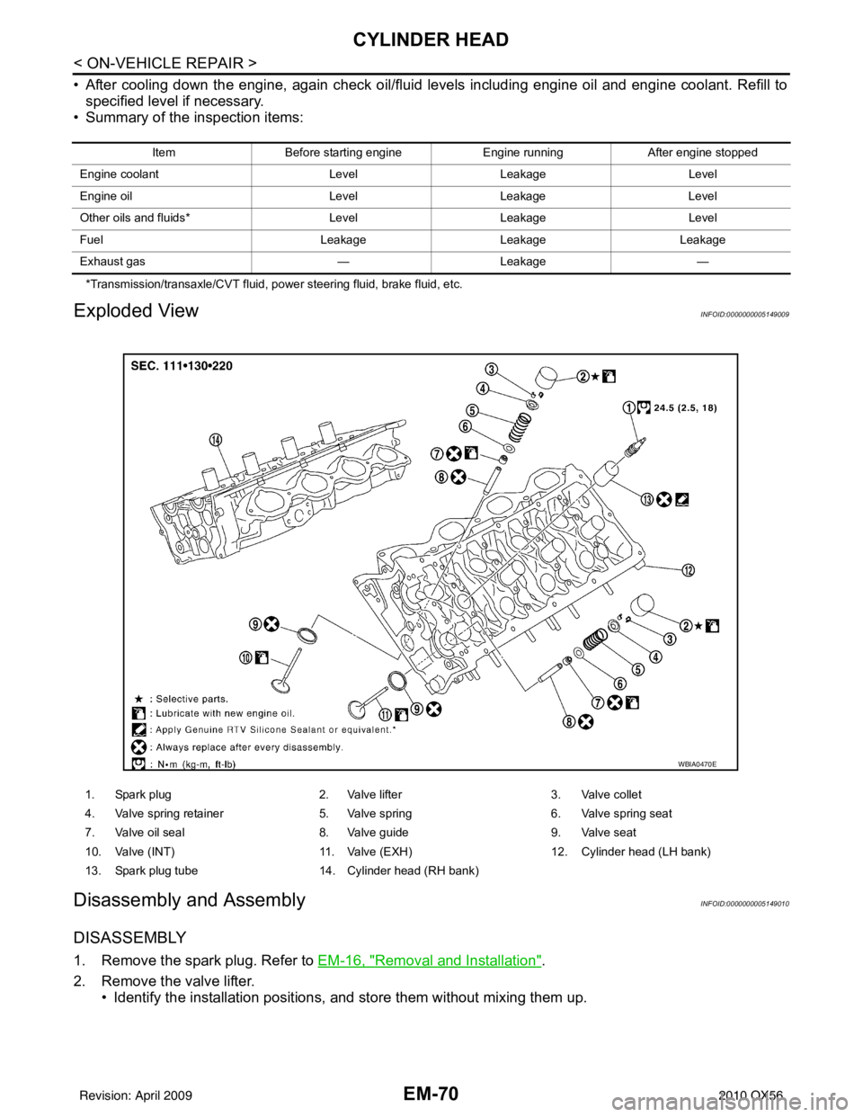
Exploded ViewINFOID:0000000005149009
Disassembly and AssemblyINFOID:0000000005149010
DISASSEMBLY
1. Remove the spark plug. Refer to EM-16, "Removal and Installation".
2. Remove the valve lifter. • Identify the installation positions, and store them without mixing them up.
Item Before starting engine Engine runningAfter engine stopped
Engine coolant LevelLeakage Level
Engine oil LevelLeakage Level
Other oils and fluids* LevelLeakage Level
Fuel LeakageLeakageLeakage
Exhaust gas —Leakage —
1. Spark plug 2. Valve lifter3. Valve collet
4. Valve spring retainer 5. Valve spring6. Valve spring seat
7. Valve oil seal 8. Valve guide9. Valve seat
10. Valve (INT) 11. Valve (EXH)12. Cylinder head (LH bank)
13. Spark plug tube 14. Cylinder head (RH bank)
WBIA0470E
Revision: April 20092010 QX56
Page 1930 of 4210
ENGINE ASSEMBLYEM-79
< REMOVAL AND INSTALLATION >
C
DE
F
G H
I
J
K L
M A
EM
NP
O
1. Release the fuel pressure. Refer to
EC-489, "Fuel Pressure Check".
2. Drain the engine coolant. Refer to CO-11, "
Changing Engine Coolant".
3. Drain the engine oil. Refer to LU-9, "
Changing Engine Oil".
4. Partially drain the A/T fluid. Refer to TM-150, "
Changing the A/T Fluid (ATF)".
5. Disconnect the battery negative and positive terminal. Refer to PG-74, "
Removal and Installation".
6. Remove the engine hood. Refer to DLK-234, "
Removal and Installation of Hood Assembly".
7. Remove the cowl extension. Refer to EXT-18, "
Removal and Installation".
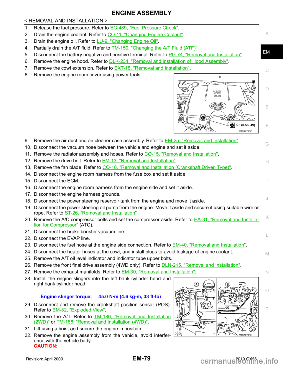
8. Remove the engine room cover using power tools.
9. Remove the air duct and air cleaner case assembly. Refer to EM-25, "
Removal and Installation".
10. Disconnect the vacuum hose between the vehicle and engine and set it aside.
11. Remove the radiator assembly and hoses. Refer to CO-15, "
Removal and Installation".
12. Remove the drive belt. Refer to EM-13, "
Removal and Installation".
13. Remove the fan blade. Refer to CO-18, "
Removal and Installation (Crankshaft Driven Type)".
14. Disconnect the engine room harness from the fuse box and set it aside.
15. Disconnect the ECM.
16. Disconnect the engine room harness from the engine side and set it aside.
17. Disconnect the engine harness grounds.
18. Disconnect the power steering reservoir t ank from the engine and move it aside.
19. Disconnect the power steering oil pump from the engine. Move it aside and secure it using suitable wire or rope. Refer to ST-26, "
Removal and Installation"
20. Remove the A/C compressor bolts and set the compressor aside. Refer to HA-31, "Removal and Installa-
tion for Compressor" (ATC).
21. Disconnect the brake booster vacuum line.
22. Disconnect the EVAP line.
23. Disconnect the fuel hose at the engine side connection. Refer to EM-40, "
Removal and Installation".
24. Disconnect the heater hoses at the cowl, and in stall plugs to avoid leakage of engine coolant.
25. Remove the A/T oil level indicator and indicator tube upper bolts.
26. Remove the front final drive assembly (4WD only). Refer to DLN-215, "
Removal and Installation".
27. Remove the exhaust manifolds. Refer to EM-30, "
Removal and Installation".
28. Install the engine slingers into the left bank cylinder head and right bank cylinder head.
29. Disconnect and remove the crankshaft position sensor (POS). Refer to EM-82, "
Exploded View".
30. Remove the A/T. Refer to TM-186, "
Removal and Installation
(2WD)" or TM-188, "Removal and Installation (4WD)".
31. Lift using a hoist and secure the engine in position.
32. Remove the engine assembly from the vehicle, avoid interfer- ence with the vehicle body.
CAUTION:
WBIA0795E
Engine slinger torque: 45.0 N·m (4.6 kg-m, 33 ft-lb)
WBIA0715E
Revision: April 20092010 QX56
Page 1932 of 4210
ENGINE ASSEMBLYEM-81
< REMOVAL AND INSTALLATION >
C
DE
F
G H
I
J
K L
M A
EM
NP
O
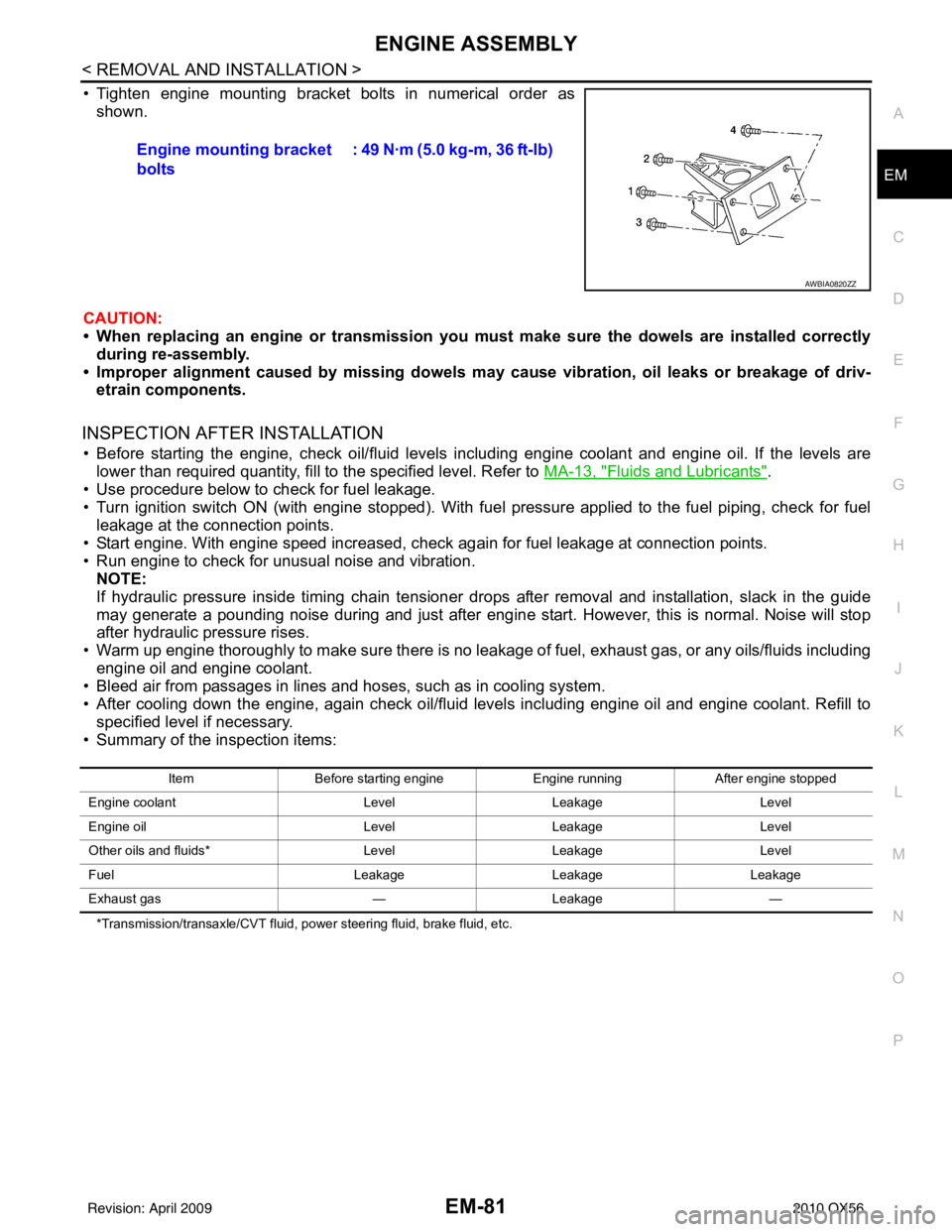
• Tighten engine mounting bracket bolts in numerical order as
shown.
CAUTION:
• When replacing an engine or tr ansmission you must make sure the dowels are installed correctly
during re-assembly.
• Improper alignment caused by missing dowels m ay cause vibration, oil leaks or breakage of driv-
etrain components.
INSPECTION AFTER INSTALLATION
• Before starting the engine, check oil/fluid levels including engine coolant and engine oil. If the levels are
lower than required quantity, fill to the specified level. Refer to MA-13, "
Fluids and Lubricants".
• Use procedure below to check for fuel leakage.
• Turn ignition switch ON (with engine stopped). With fuel pressure applied to the fuel piping, check for fuel leakage at the connection points.
• Start engine. With engine speed increased, check again for fuel leakage at connection points.
• Run engine to check for unusual noise and vibration. NOTE:
If hydraulic pressure inside timing chain tensioner drops after removal and installation, slack in the guide
may generate a pounding noise during and just after engine start. However, this is normal. Noise will stop
after hydraulic pressure rises.
• Warm up engine thoroughly to make sure there is no leakage of fuel, exhaust gas, or any oils/fluids including engine oil and engine coolant.
• Bleed air from passages in lines and hoses, such as in cooling system.
• After cooling down the engine, again check oil/fluid levels including engine oil and engine coolant. Refill to
specified level if necessary.
• Summary of the inspection items:
*Transmission/transaxle/CVT fluid, power steering fluid, brake fluid, etc.
Engine mounting bracket
bolts : 49 N·m (5.0 kg-m, 36 ft-lb)
AWBIA0820ZZ
Item
Before starting engine Engine runningAfter engine stopped
Engine coolant LevelLeakage Level
Engine oil LevelLeakage Level
Other oils and fluids* LevelLeakage Level
Fuel LeakageLeakage Leakage
Exhaust gas —Leakage —
Revision: April 20092010 QX56