Page 2919 of 4210
PG
POWER SUPPLY ROUTING CIRCUITPG-9
< COMPONENT DIAGNOSIS >
C
DE
F
G H
I
J
K L
B A
O P
N
COMPONENT DIAGNOSIS
POWER SUPPLY ROUTING CIRCUIT
Wiring Diagram —Battery Power Supply —INFOID:0000000005146576
ABMWA0428GB
Revision: April 20092010 QX56
Page 2928 of 4210
PG-18
< COMPONENT DIAGNOSIS >
POWER SUPPLY ROUTING CIRCUIT
Wiring Diagram —Accessory Power Supply —
INFOID:0000000005146577
ABMWA0433GB
Revision: April 20092010 QX56
Page 2932 of 4210
PG-22
< COMPONENT DIAGNOSIS >
POWER SUPPLY ROUTING CIRCUIT
Wiring Diagram —Igniti on Power Supply —
INFOID:0000000005146578
ABMWA0066GB
Revision: April 20092010 QX56
Page 2940 of 4210

PG-30
< COMPONENT DIAGNOSIS >
POWER SUPPLY ROUTING CIRCUIT
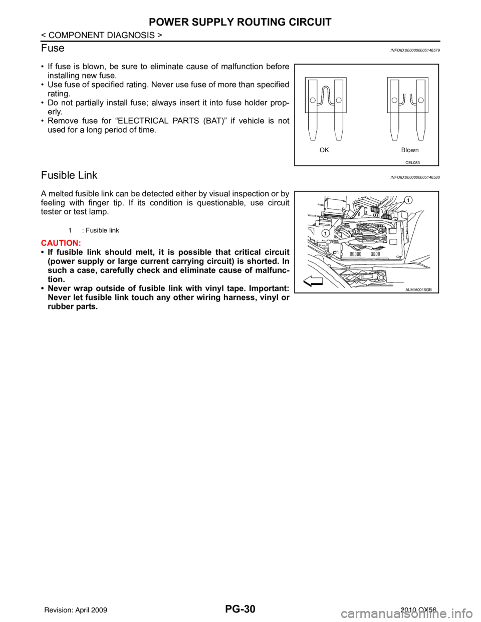
Fuse
INFOID:0000000005146579
• If fuse is blown, be sure to eliminate cause of malfunction before installing new fuse.
• Use fuse of specified rating. Never use fuse of more than specified
rating.
• Do not partially install fuse; always insert it into fuse holder prop- erly.
• Remove fuse for “ELECTRICAL PARTS (BAT)” if vehicle is not used for a long period of time.
Fusible LinkINFOID:0000000005146580
A melted fusible link can be detected either by visual inspection or by
feeling with finger tip. If its condition is questionable, use circuit
tester or test lamp.
CAUTION:
• If fusible link should melt, it is possible that critical circuit
(power supply or large current carrying circuit) is shorted. In
such a case, carefully check and eliminate cause of malfunc-
tion.
• Never wrap outside of fusible link with vinyl tape. Important: Never let fusible link touch an y other wiring harness, vinyl or
rubber parts.
CEL083
1 : Fusible link
ALMIA0015GB
Revision: April 20092010 QX56
Page 2954 of 4210

PG-44
< COMPONENT DIAGNOSIS >
HARNESS
D2 M55 W/4 : Hazard switchD5 M207 B/3 : Console power socket
D4 M56 W/16 : To M201 C4 M208 BR/20 : To M69
A3 M57 — : Body ground C5 M209 W/2 : Center console area antenna (rear)
F2 M58 B/6 : Intake door motor C4 M210 GR/2 : Center console area antenna (front)
F3 M59 BR/2 : Glove box lamp C4 M212 W/6 : Rear heated seat switch LH
G3 M60 W/6 : Fuse block (J/B) C4 M213 BR/6 : Rear heated seat switch RH
C3 M61 — : Body ground Console switch sub-harness
F4 M62 B/2 : Front blower motor D4 M251 BR/20 : To M63
D4 M63 BR/20 : To M251 D4 M252 BR/6 : Front heated seat switch RH
D4 M64 BR/24 : To M202 C4 M253 GR/6 : VDC OFF switch
F2 M65 W/4 : To M301 C3 M255 W/6 : Front heated seat switch LH
G3 M66 B/1 : To E33 C4 M256 B/2 : A/T shift selector
C3 M69 BR/20 : To M208 D4 M258 GR/8 : Tow mode switch
A2 M70 W/40 : Intelligent key unit C4 M260 W/6 : Heated steering wheel switch
A2 M71 L/4 : Heated steering relay Optical sensor sub-harness
D3 M73 BR/6 : Back-up lamp relay F1 M301 W/4 : To M65
G3 M74 BR/20 : To D102 D1 M302 B/4 : Optical sensor
G3 M75 W/10 : To D101
A3 M76 W/6 : Electric brake (pre-wiring)
E2 M77 Y/4 : Front passenger air bag module
(service replacement)
Revision: April 20092010 QX56
Page 2983 of 4210
PG
IPDM E/R (INTELLIGENT POWER DISTRIBUTION MODULE ENGINE ROOM)
PG-73
< COMPONENT DIAGNOSIS >
C
D E
F
G H
I
J
K L
B A
O P
N
IPDM E/R Terminal Ar
rangement - Type BINFOID:0000000005370328
NOTE:
Numbers preceded by an "F" represent the fuse number s imprinted on the IPDM E/R. The other numbers
represent the fuse numbers as they appear in the wiring diagrams.
AAMIA0364GB
Revision: April 20092010 QX56
Page 2987 of 4210

PWC-2
PASSENGER SIDE : Description ...........................25
PASSENGER SIDE : Compo nent Function Check
...
25
PASSENGER SIDE : Diagnosis Procedure ........ ...25
REAR LH ................................................................ ...28
REAR LH : Description ...........................................28
REAR LH : Component Function Check ................28
REAR LH : Diagnosis Procedure ............................28
REAR RH ............................................................... ...30
REAR RH : Description ..........................................31
REAR RH : Component Function Check ................31
REAR RH : Diagnosis Procedure ...........................31
DOOR SWITCH .................................................34
Description ..............................................................34
Component Function Check ...................................34
Diagnosis Procedure ..............................................34
Component Inspection ............................................35
DOOR KEY CYLINDER SWITCH ......................36
Description ........................................................... ...36
Component Function Check ...................................36
Diagnosis Procedure ..............................................36
Component Inspection ............................................37
POWER WINDOW SERIAL LINK .....................39
POWER WINDOW MAIN SWITCH ........................ ...39
POWER WINDOW MAIN SWITCH : Description ...39
POWER WINDOW MAIN SWITCH : Component
Function Check .......................................................
39
POWER WINDOW MAIN SWITCH : Diagnosis
Procedure ...............................................................
39
FRONT POWER WINDOW SWITCH ..................... ...40
FRONT POWER WINDOW SWITCH : Descrip-
tion ..........................................................................
40
FRONT POWER WINDOW SWITCH : Compo-
nent Function Check ...............................................
40
FRONT POWER WINDOW SWITCH : Diagnosis
Procedure ...............................................................
41
REAR POWER WINDOW SWITCH ....................... ...42
REAR POWER WINDOW SWITCH : Power Win-
dow Serial Link Check Rear LH or RH ...................
42
POWER WINDOW LOCK SWITCH ...................43
Description ........................................................... ...43
Component Function Check ...................................43
REAR POWER VENT WINDOW SWITCH
CIRCUIT CHECK ...............................................
44
Description ........................................................... ...44
Diagnosis Procedure ..............................................44
REAR POWER VENT WINDOW MOTOR LH
CIRCUIT CHECK ...............................................
45
Description ........................................................... ...45
Diagnosis Procedure ..............................................45
REAR POWER VENT WINDOW MOTOR RH
CIRCUIT CHECK ...............................................
46
Description ........................................................... ...46
Diagnosis Procedure ...............................................46
REAR POWER VENT WINDOW RELAY
(OPEN) CHECK .................................................
47
Description ........................................................... ...47
Diagnosis Procedure ...............................................47
REAR POWER VENT WINDOW RELAY
(CLOSE) CHECK ...............................................
49
Description ........................................................... ...49
Diagnosis Procedure ...............................................49
ECU DIAGNOSIS .......................................51
POWER WINDOW MAIN SWITCH ................ ...51
Reference Value .................................................. ...51
Wiring Diagram .......................................................53
Fail Safe .................................................................64
FRONT POWER WINDOW SWITCH ................66
Reference Value .................................................. ...66
Wiring Diagram .......................................................68
Fail Safe .................................................................79
BCM (BODY CONTROL MODULE) ..................81
Reference Value .................................................. ...81
Terminal Layout ......................................................84
Physical Values .......................................................84
Wiring Diagram .......................................................90
Fail Safe .................................................................94
DTC Inspection Priority Chart ...............................95
DTC Index ..............................................................95
SYMPTOM DIAGNOSIS ............................97
NONE OF THE POWER WINDOWS CAN BE
OPERATED USING ANY SWITCH ................ ...
97
Diagnosis Procedure ............................................ ...97
DRIVER SIDE POWER WINDOW ALONE
DOES NOT OPERATE ......................................
98
Diagnosis Procedure ............................................ ...98
FRONT PASSENGER SIDE POWER WIN-
DOW ALONE DOES NOT OPERATE ...............
99
Diagnosis Procedure ............................................ ...99
REAR LH SIDE POWER WINDOW ALONE
DOES NOT OPERATE .....................................
100
Diagnosis Procedure ............................................ .100
REAR RH SIDE POWER WINDOW ALONE
DOES NOT OPERATE .....................................
101
Diagnosis Procedure ............................................ .101
ANTI-PINCH SYSTEM DOES NOT OPERATE
NORMALLY (DRIVER SIDE) ...........................
102
Diagnosis Procedure ............................................ .102
Revision: April 20092010 QX56
Page 2997 of 4210

PWC-12
< COMPONENT DIAGNOSIS >
POWER SUPPLY AND GROUND CIRCUIT
COMPONENT DIAGNOSIS
POWER SUPPLY AND GROUND CIRCUIT
POWER WINDOW MAIN SWITCH
POWER WINDOW MAIN SWITCH : DescriptionINFOID:0000000005147171
• BCM supplies power.
• It operates each power window motor via corresponding power window switch and makes window move up/down when main power window and door lock/unlock switch is operated.
POWER WINDOW MAIN SWITCH : Component Function CheckINFOID:0000000005147172
Main Power Window And Door Lock/Unlock Switch
1. CHECK MAIN POWER WINDOW AND DO OR LOCK/UNLOCK SWITCH FUNCTION
Does power window motor operate with main power window and door lock/unlock switch operation?
Is the inspection result normal?
YES >> Main power window and door lock/unlock switch power supply and ground circuit are OK.
NO >> Refer to PWC-12, "
POWER WINDOW MAIN SWITCH : Diagnosis Procedure".
POWER WINDOW MAIN SWITCH : Diagnosis ProcedureINFOID:0000000005147173
Regarding Wiring Diagram information, refer to PWC-53, "Wiring Diagram".
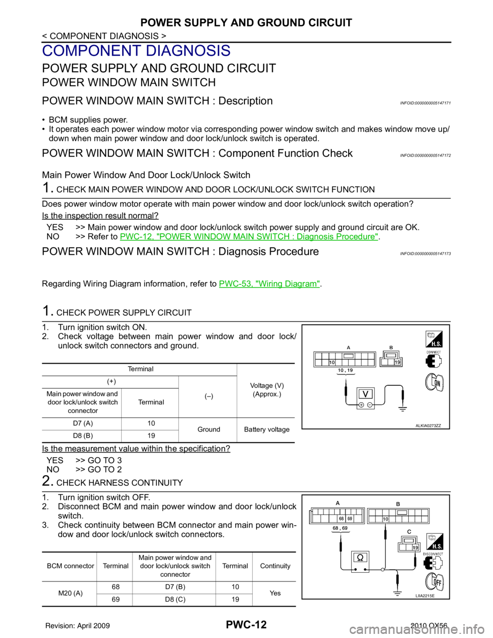
1. CHECK POWER SUPPLY CIRCUIT
1. Turn ignition switch ON.
2. Check voltage between main power window and door lock/ unlock switch connectors and ground.
Is the measurement value within the specification?
YES >> GO TO 3
NO >> GO TO 2
2. CHECK HARNESS CONTINUITY
1. Turn ignition switch OFF.
2. Disconnect BCM and main power window and door lock/unlock switch.
3. Check continuity between BCM connector and main power win- dow and door lock/unlock switch connectors.
Te r m i n a l
Voltage (V)(Approx.)
(+)
(–)
Main power window and
door lock/unlock switch
connector Te r m i n a l
D7 (A) 10
Ground Battery voltage
D8 (B) 19
ALKIA0273ZZ
BCM connector Terminal Main power window and
door lock/unlock switch connector Terminal Continuity
M20 (A) 68
D7 (B) 10
Ye s
69 D8 (C) 19
LIIA2215E
Revision: April 20092010 QX56