2010 INFINITI QX56 oil
[x] Cancel search: oilPage 3847 of 4210
TM-152
< ON-VEHICLE MAINTENANCE >
A/T FLUID COOLER
A/T FLUID COOLER
A/T Fluid Cooler CleaningINFOID:0000000005148724
Whenever an A/T is repaired, overhauled, or replaced, the A/T fluid cooler mounted in the radiator must be
inspected and cleaned.
Metal debris and friction material, if present, can become trapped in the A/T fluid cooler. This debris can con-
taminate the newly serviced A/T or, in severe cases, can bloc k or restrict the flow of A/T fluid. In either case,
malfunction of the newly serviced A/T may result.
Debris, if present, may build up as A/T fluid enters the c ooler inlet. It will be necessary to back flush the cooler
through the cooler outlet in order to flush out any built up debris.
A/T FLUID COOLER CLEANING PROCEDURE
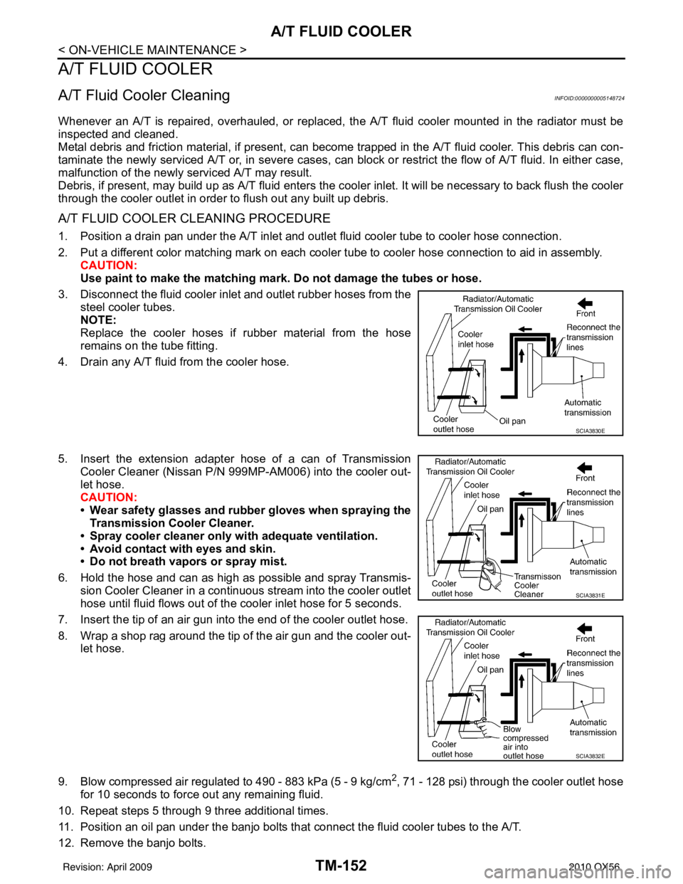
1. Position a drain pan under the A/T inlet and outlet fluid cooler tube to cooler hose connection.
2. Put a different color matching mark on each cooler tube to cooler hose connection to aid in assembly. CAUTION:
Use paint to make the matching mark. Do not damage the tubes or hose.
3. Disconnect the fluid cooler inlet and outlet rubber hoses from the steel cooler tubes.
NOTE:
Replace the cooler hoses if rubber material from the hose
remains on the tube fitting.
4. Drain any A/T fluid from the cooler hose.
5. Insert the extension adapter hose of a can of Transmission
Cooler Cleaner (Nissan P/N 999MP-AM006) into the cooler out-
let hose.
CAUTION:
• Wear safety glasses and rubber gloves when spraying the Transmission Cooler Cleaner.
• Spray cooler cleaner only wi th adequate ventilation.
• Avoid contact with eyes and skin.
• Do not breath vapors or spray mist.
6. Hold the hose and can as high as possible and spray Transmis- sion Cooler Cleaner in a continuous stream into the cooler outlet
hose until fluid flows out of the cooler inlet hose for 5 seconds.
7. Insert the tip of an air gun into the end of the cooler outlet hose.
8. Wrap a shop rag around the tip of the air gun and the cooler out- let hose.
9. Blow compressed air regulated to 490 - 883 kPa (5 - 9 kg/cm
2, 71 - 128 psi) through the cooler outlet hose
for 10 seconds to force out any remaining fluid.
10. Repeat steps 5 through 9 three additional times.
11. Position an oil pan under the banjo bolts that connect the fluid cooler tubes to the A/T.
12. Remove the banjo bolts.
SCIA3830E
SCIA3831E
SCIA3832E
Revision: April 20092010 QX56
Page 3849 of 4210
TM-154
< ON-VEHICLE MAINTENANCE >
A/T FLUID COOLER
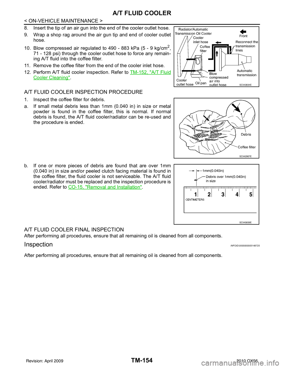
8. Insert the tip of an air gun into the end of the cooler outlet hose.
9. Wrap a shop rag around the air gun tip and end of cooler outlethose.
10. Blow compressed air regulated to 490 - 883 kPa (5 - 9 kg/cm
2,
71 - 128 psi) through the cooler outlet hose to force any remain-
ing A/T fluid into the coffee filter.
11. Remove the coffee filter from the end of the cooler inlet hose.
12. Perform A/T fluid cooler inspection. Refer to TM-152, "
A/T Fluid
Cooler Cleaning".
A/T FLUID COOLER INSPECTION PROCEDURE
1. Inspect the coffee filter for debris.
a. If small metal debris less than 1mm (0.040 in) in size or metal
powder is found in the coffee filter, this is normal. If normal
debris is found, the A/T fluid cooler/radiator can be re-used and
the procedure is ended.
b. If one or more pieces of debris are found that are over 1mm (0.040 in) in size and/or peeled clutch facing material is found in
the coffee filter, the fluid cooler is not serviceable. The A/T fluid
cooler/radiator must be replaced and the inspection procedure is
ended. Refer to CO-15, "
Removal and Installation".
A/T FLUID COOLER FINAL INSPECTION
After performing all procedures, ensure that all remaining oil is cleaned from all components.
InspectionINFOID:0000000005148725
After performing all procedures, ensure that all remaining oil is cleaned from all components.
SCIA3834E
SCIA2967E
SCIA5659E
Revision: April 20092010 QX56
Page 3850 of 4210
STALL TESTTM-155
< ON-VEHICLE MAINTENANCE >
CEF
G H
I
J
K L
M A
B
TM
N
O P
STALL TEST
Inspection and JudgmentINFOID:0000000005148726
A/T FLUID CHECK
Fluid Leakage and Fluid Level Check
• Inspect for fluid leakage and check the fluid level. Refer to TM-148, "Checking the A/T Fluid (ATF)".
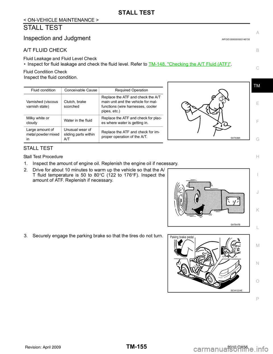
Fluid Condition Check
Inspect the fluid condition.
STALL TEST
Stall Test Procedure
1. Inspect the amount of engine oil. Replenish the engine oil if necessary.
2. Drive for about 10 minutes to warm up the vehicle so that the A/
T fluid temperature is 50 to 80 °C (122 to 176 °F). Inspect the
amount of ATF. Replenish if necessary.
3. Securely engage the parking brake so that the tires do not turn.
Fluid condition Conceivable Cause Required Operation
Varnished (viscous
varnish state) Clutch, brake
scorchedReplace the ATF and check the A/T
main unit and the vehicle for mal-
functions (wire harnesses, cooler
pipes, etc.)
Milky white or
cloudy Water in the fluidReplace the ATF and check for plac-
es where water is getting in.
Large amount of
metal powder mixed
in Unusual wear of
sliding parts within
A/T
Replace the ATF and check for im-
proper operation of the A/T.
SAT638A
SAT647B
SCIA1224E
Revision: April 20092010 QX56
Page 3852 of 4210
LINE PRESSURE TESTTM-157
< ON-VEHICLE MAINTENANCE >
CEF
G H
I
J
K L
M A
B
TM
N
O P
LINE PRESSURE TEST
Inspection and JudgmentINFOID:0000000005148727
LINE PRESSURE TEST
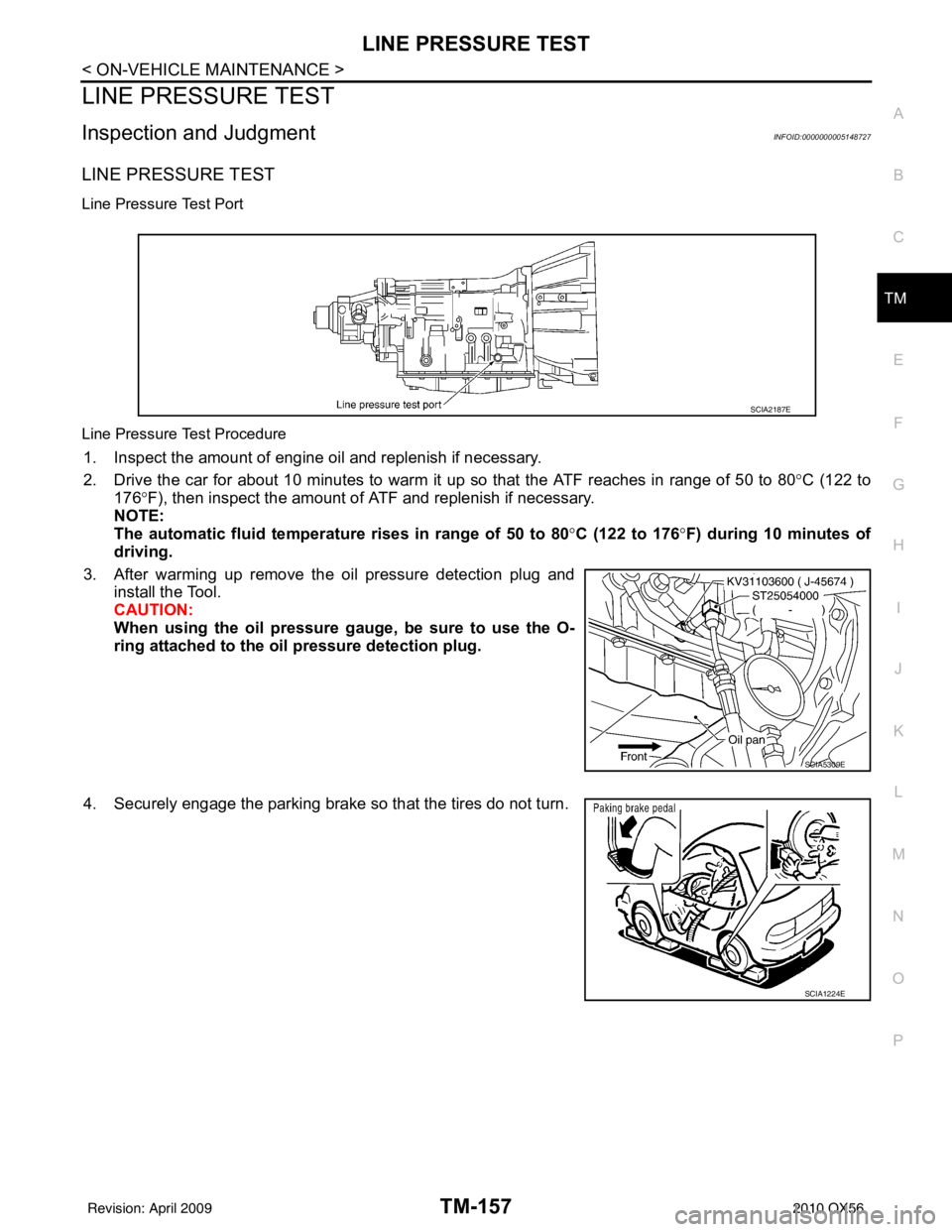
Line Pressure Test Port
Line Pressure Test Procedure
1. Inspect the amount of engine oil and replenish if necessary.
2. Drive the car for about 10 minutes to warm it up so that the ATF reaches in range of 50 to 80 °C (122 to
176° F), then inspect the amount of ATF and replenish if necessary.
NOTE:
The automatic fluid temperature rises in range of 50 to 80 °C (122 to 176° F) during 10 minutes of
driving.
3. After warming up remove the oil pressure detection plug and install the Tool.
CAUTION:
When using the oil pressure ga uge, be sure to use the O-
ring attached to the oil pressure detection plug.
4. Securely engage the parking brake so that the tires do not turn.
SCIA2187E
SCIA5309E
SCIA1224E
Revision: April 20092010 QX56
Page 3853 of 4210
TM-158
< ON-VEHICLE MAINTENANCE >
LINE PRESSURE TEST
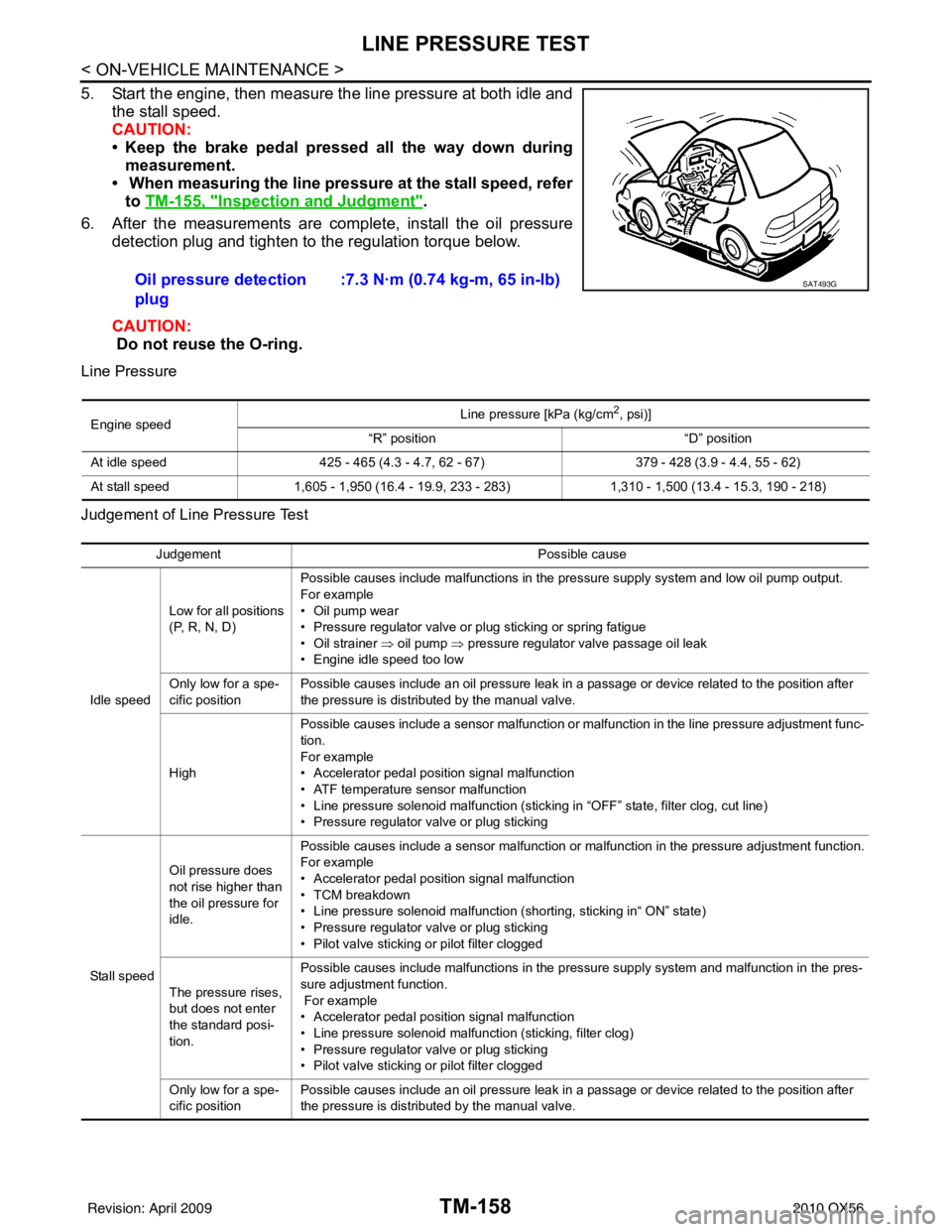
5. Start the engine, then measure the line pressure at both idle andthe stall speed.
CAUTION:
• Keep the brake pedal pressed all the way down duringmeasurement.
• When measuring the line pressure at the stall speed, refer
to TM-155, "
Inspection and Judgment".
6. After the measurements are complete, install the oil pressure detection plug and tighten to the regulation torque below.
CAUTION:
Do not reuse the O-ring.
Line Pressure
Judgement of Line Pressure Test
Oil pressure detection
plug :7.3 N·m (0.74 kg-m, 65 in-lb)SAT493G
Engine speed
Line pressure [kPa (kg/cm
2, psi)]
“R” position “D” position
At idle speed 425 - 465 (4.3 - 4.7, 62 - 67) 379 - 428 (3.9 - 4.4, 55 - 62)
At stall speed 1,605 - 1,950 (16.4 - 19.9, 233 - 283) 1,310 - 1,500 (13.4 - 15.3, 190 - 218)
Judgement Possible cause
Idle speed Low for all positions
(P, R, N, D)
Possible causes include malfunctions in the pressure supply system and low oil pump output.
For example
•Oil pump wear
• Pressure regulator valve or plug sticking or spring fatigue
• Oil strainer ⇒ oil pump
⇒ pressure regulator valve passage oil leak
• Engine idle speed too low
Only low for a spe-
cific position Possible causes include an oil pressure leak in a passage or device related to the position after
the pressure is distributed by the manual valve.
High Possible causes include a sensor malfunction or malfunction in the line pressure adjustment func-
tion.
For example
• Accelerator pedal position signal malfunction
• ATF temperature sensor malfunction
• Line pressure solenoid malfunction (sticking in “OFF” state, filter clog, cut line)
• Pressure regulator valve or plug sticking
Sta ll sp ee d Oil pressure does
not rise higher than
the oil pressure for
idle.
Possible causes include a sensor malfunction or malfunction in the pressure adjustment function.
For example
• Accelerator pedal position signal malfunction
• TCM breakdown
• Line pressure solenoid malfunction (shorting, sticking in“ ON” state)
• Pressure regulator valve or plug sticking
• Pilot valve sticking or pilot filter clogged
The pressure rises,
but does not enter
the standard posi-
tion. Possible causes include malfunctions in the pressure supply system and malfunction in the pres-
sure adjustment function.
For example
• Accelerator pedal position signal malfunction
• Line pressure solenoid malfunction (sticking, filter clog)
• Pressure regulator valve or plug sticking
• Pilot valve sticking or pilot filter clogged
Only low for a spe-
cific position Possible causes include an oil pressure leak in a passage or device related to the position after
the pressure is distributed by the manual valve.
Revision: April 20092010 QX56
Page 3855 of 4210
TM-160
< ON-VEHICLE MAINTENANCE >
ROAD TEST
YES >> Record the malfunction, GO TO 4.
NO >> GO TO 4.
4.CHECK “N” POSITION FUNCTIONS
1. Start the engine.
2. Move selector lever to “N” position.
3. Release the parking brake.
Does vehicle move forward or backward?
YES >> Record the malfunction, GO TO 5.
NO >> GO TO 5.
5.CHECK SHIFT SHOCK
1. Engage the brake.
2. Move selector lever to “D” position.
When the transmission is shifted from
“N” to “D”, is there an excessive shock?
YES >> Record the malfunction, GO TO 6.
NO >> GO TO 6.
6.CHECK “R” POSITION FUNCTIONS
1. Engage the brake.
2. Move selector lever to “R” position.
3. Release the brake for 4 to 5 seconds.
Does the vehicle creep backward?
YES >> GO TO 7.
NO >> Record the malfunction, GO TO 7.
7.CHECK “D” POSITION FUNCTIONS
Inspect whether the vehicle creeps forward when the transmission is put into the “D” position.
Does the vehicle creep forward in the
“D” positions?
YES >> Go to TM-160, "Cruise Test - Part 1".
NO >> Record the malfunction and go to TM-160, "
Cruise Test - Part 1".
Cruise Test - Part 1INFOID:0000000005148731
1.CHECK STARTING OUT FROM D1
1. Drive the vehicle for about 10 minutes to warm up the engine oil and ATF. Appropriate temperature for the ATF: 50 - 80° C (122 - 176°F)
2. Park the vehicle on a level surface.
3. Move selector lever to “P” position.
4. Start the engine.
5. Move selector lever to “D” position.
6. Press the accelerator pedal about half way down to accelerate the vehicle.
With CONSULT-III
Read off the gear positions.
Starts from D1?
YES >> GO TO 2.
NO >> Record the malfunction, GO TO 2.
2.CHECK SHIFT-UP D1 → D2
Press down the accelerator pedal about half way and inspect if the vehicle shifts up (D1 → D2) at the appropri-
ate speed.
• Refer to TM-265, "
Vehicle Speed at Which Gear Shifting Occurs".
With CONSULT-III
Read the gear position, throttle degree of opening, and vehicle speed.
Does the A/T shift-up D1
→ D2 at the correct speed?
YES >> GO TO 3.
NO >> Record the malfunction, GO TO 3.
Revision: April 20092010 QX56
Page 3865 of 4210
TM-170
< ON-VEHICLE REPAIR >
OIL PAN
OIL PAN
Oil PanINFOID:0000000005148740
REMOVAL AND INSTALLATION
Removal
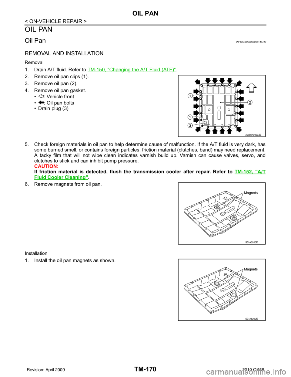
1. Drain A/T fluid. Refer to TM-150, "Changing the A/T Fluid (ATF)".
2. Remove oil pan clips (1).
3. Remove oil pan (2).
4. Remove oil pan gasket. • : Vehicle front
• : Oil pan bolts
• Drain plug (3)
5. Check foreign materials in oil pan to help determine c ause of malfunction. If the A/T fluid is very dark, has
some burned smell, or contains foreign particles, friction material (clutches, band) may need replacement.
A tacky film that will not wipe clean indicates varnish build up. Varnish can cause valves, servo, and
clutches to stick and can inhibit pump pressure.
CAUTION:
If friction material is detected, flush the transmission cooler after repair. Refer to TM-152, "
A/T
Fluid Cooler Cleaning".
6. Remove magnets from oil pan.
Installation
1. Install the oil pan magnets as shown.
AWDIA0023ZZ
SCIA5200E
SCIA5200E
Revision: April 20092010 QX56
Page 3866 of 4210
OIL PANTM-171
< ON-VEHICLE REPAIR >
CEF
G H
I
J
K L
M A
B
TM
N
O P
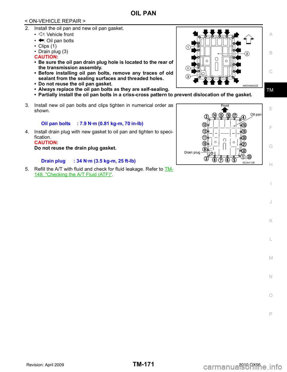
2. Install the oil pan and new oil pan gasket. • : Vehicle front
• : Oil pan bolts
• Clips (1)
• Drain plug (3)
CAUTION:
• Be sure the oil pan drain plug hole is located to the rear ofthe transmission assembly.
• Before installing oil pan bolts, remove any traces of old sealant from the sealing su rfaces and threaded holes.
• Do not reuse the oil pan gasket.
• Always replace the oil pan bolts as they are self-sealing.
• Partially install the oil pan bo lts in a criss-cross pattern to prevent dislocation of the gasket.
3. Install new oil pan bolts and clips tighten in numerical order as shown.
4. Install drain plug with new gasket to oil pan and tighten to speci- fication.
CAUTION:
Do not reuse the drain plug gasket.
5. Refill the A/T with fluid and check for fluid leakage. Refer to TM-
148, "Checking the A/T Fluid (ATF)".
AWDIA0023ZZ
Oil pan bolts : 7.9 N·m (0.81 kg-m, 70 in-lb)
Drain plug : 34 N·m (3.5 kg-m, 25 ft-lb)
SCIA4113E
Revision: April 20092010 QX56