Page 2786 of 4210
![INFINITI QX56 2010 Factory Service Manual MWI-24
< FUNCTION DIAGNOSIS >
DIAGNOSIS SYSTEM (METER)
X: Applicable
Display item [Unit]MAIN
SIGNALS SELECTION
FROM MENU Description
SPEED METER [km/h] or [mph] X X Displays the value of vehicle spee INFINITI QX56 2010 Factory Service Manual MWI-24
< FUNCTION DIAGNOSIS >
DIAGNOSIS SYSTEM (METER)
X: Applicable
Display item [Unit]MAIN
SIGNALS SELECTION
FROM MENU Description
SPEED METER [km/h] or [mph] X X Displays the value of vehicle spee](/manual-img/42/57032/w960_57032-2785.png)
MWI-24
< FUNCTION DIAGNOSIS >
DIAGNOSIS SYSTEM (METER)
X: Applicable
Display item [Unit]MAIN
SIGNALS SELECTION
FROM MENU Description
SPEED METER [km/h] or [mph] X X Displays the value of vehicle speed signal.
SPEED OUTPUT [km/h] or [mph] X XDisplays the value of vehicle speed signal, which is transmitted to
each unit with
CAN communication.
TACHO METER [rpm] XX Displays the value of engine speed signal, which is input from ECM.
FUEL METER [lit.] XXDisplays the value, which processes a resistance signal from fuel
gauge.
W TEMP METER [ °C] or [° F] X XDisplays the value of engine coolant temperature signal, which is in-
put from ECM.
ABS W/L [ON/OFF] X Displays [ON/OFF] condition of ABS warning lamp.
VDC/TCS IND [ON/OFF] X Displays [ON/OFF] condition of VDC OFF indicator lamp.
SLIP IND [ON/OFF] X Displays [ON/OFF] condition of SLIP indicator lamp.
BRAKE W/L [ON/OFF] X Displays [ON/OFF] condition of brake warning lamp.*
DOOR W/L [ON/OFF] X Displays [ON/OFF] condition of door warning lamp.
TRUNK W/L [ON/OFF] X Displays [ON/OFF] condition of glass hatch warning lamp.
HI-BEAM IND [ON/OFF] X Displays [ON/OFF] condition of high beam indicator.
TURN IND [ON/OFF] X Displays [ON/OFF] conditio n of turn indicator.
OIL W/L [ON/OFF] X Displays [ON/OFF] condition of oil pressure warning lamp.
C-ENG W/L [ON/OFF] X Displays [ON/OFF] condition of malfunction indicator lamp.
CRUISE IND [ON/OFF] X Displays [ON/OFF] condition of CRUISE indicator.
SET IND [ON/OFF] X Displays [ON/OFF] condition of SET indicator.
AT CHECK W/L [ON/OFF] X Displays [ON/OFF] condition of AT CHECK warning lamp.
FUEL W/L [ON/OFF] XX Displays [ON/OFF] condition of low-fuel warning lamp.
AIR PRES W/L [ON/OFF] X Displays [ON/OFF] condition of tire pressure warning lamp.
KEY G/Y W/L [ON/OFF] X Displays [ON/OFF] condition of key green warning lamp.
KEY R W/L [ON/OFF] X Displays [ON/OFF] condition of key red warning lamp.
KEY KNOB W/L [ON/OFF] X Displays [ON/OFF] condition of key knob warning lamp.
M RANGE SW [ON/OFF] XX Displays [ON/OFF] condition of manual mode range switch.
NM RANGE SW [ON/OFF] XXDisplays [ON/OFF] condition of except for manual mode range
switch.
AT SFT UP SW [ON/OFF] XX Displays [ON/OFF] condition of A/T shift-up switch.
AT SFT DWN SW [ON/OFF] XX Displays [ON/OF F] condition of A/T shift-down switch.
DISTANCE [km] or [mile] XXDisplays the value, which is calculated by vehicle speed signal, fuel
gauge and fuel consumption from ECM.
BUZZER [ON/OFF] XX Displays [ON/ OFF] condition of buzzer.
BRAKE SW [ON/OFF] X Indicates [ON/OFF] condition of parking brake switch.
AT-M GEAR [1, 2, 3, 4] XX Indicates [1, 2, 3, 4] condition of A/T manual mode gear position.
P RANGE IND [ON/OFF] XX Indicates [ON/OFF] condition of A/T shift P range indicator.
R RANGE IND [ON/OFF] XX Indicates [ON/OFF] condition of A/T shift R range indicator.
N RANGE IND [ON/OFF] XX Indicates [ON/OFF] condition of A/T shift N range indicator.
D RANGE IND [ON/OFF] XX Indicates [ON/OFF] condition of A/T shift D range indicator.
4 RANGE IND [ON/OFF] XX Indicates [ON/OFF] condition of A/T shift 4 range indicator.
3 RANGE IND [ON/OFF] XX Indicates [ON/OFF] condition of A/T shift 3 range indicator.
2 RANGE IND [ON/OFF] XX Indicates [ON/OFF] condition of A/T shift 2 range indicator.
1 RANGE IND [ON/OFF] XX Indicates [ON/OFF] condition of A/T shift 1range indicator.
Revision: April 20092010 QX56
Page 2787 of 4210
MWI
DIAGNOSIS SYSTEM (METER)MWI-25
< FUNCTION DIAGNOSIS >
C
DE
F
G H
I
J
K L
M B A
O P
NOTE:
Some items are not available due to vehicle specification.
*: The monitor will indicate “OFF” even though the brake warnin g lamp is on if either of the following conditions exist.
• The parking brake is engaged
• The brake fluid level is low CRUISE W/L [ON/OFF]
X Indicates [ON/OFF] condition of CRUISE warning lamp.
4WD LOCK SW [ON/OFF] X Indicates [ON/OFF] condition of 4WD lock switch.
4WD LOCK IND [ON/OFF] X Indicates [ON/OFF] condition of 4WD lock indicator.
SEAT BELT W/L [ON/OFF] X Indicates [ON/OFF] condition of seat belt warning lamp.
LIGHT IND [ON/OFF] X Indicates [ON/OFF] condition of light indicator.
4WD W/L [ON/OFF] X Indicates [ON/OFF] condition of 4WD warning lamp.
Display item [Unit]
MAIN
SIGNALS SELECTION
FROM MENU Description
Revision: April 20092010 QX56
Page 2788 of 4210
MWI-26
< COMPONENT DIAGNOSIS >
DTC U1000 CAN COMMUNICATION
COMPONENT DIAGNOSIS
DTC U1000 CAN COMMUNICATION
DTC LogicINFOID:0000000005146073
DTC DETECTION LOGIC
Diagnosis ProcedureINFOID:0000000005146074
Symptom: Displays “CAN COMM CIRC [U1000]” as a self-diagnosis result of combination meter.
1.CHECK CAN COMMUNICATION
Select “SELF-DIAG RESULTS” mode for “METER/M&A” with CONSULT-III.
>> Go to “LAN system”. Refer to LAN-14, "
Trouble Diagnosis Flow Chart".
DTC CONSULT-III display Detection condition
U1000 CAN COMM CIRC
[U1000] When combination meter is not receiving CAN communication signals for 2 seconds or more.
Revision: April 20092010 QX56
Page 2789 of 4210

MWI
DTC B2205 VEHICLE SPEED CIRCUITMWI-27
< COMPONENT DIAGNOSIS >
C
DE
F
G H
I
J
K L
M B A
O P
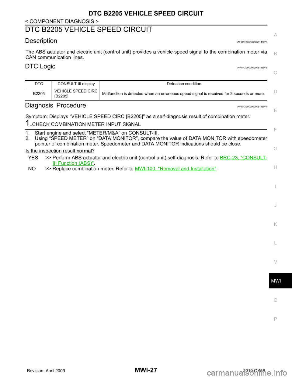
DTC B2205 VEHICLE SPEED CIRCUIT
DescriptionINFOID:0000000005146075
The ABS actuator and electric unit (control unit) provi des a vehicle speed signal to the combination meter via
CAN communication lines.
DTC LogicINFOID:0000000005146076
Diagnosis ProcedureINFOID:0000000005146077
Symptom: Displays “VEHICLE SPEED CIRC [B2205]” as a self-diagnosis result of combination meter.
1.CHECK COMBINATION METER INPUT SIGNAL
1. Start engine and select “M ETER/M&A” on CONSULT-III.
2. Using “SPEED METER” on “DATA MONITOR”, compare the value of DATA MONITOR with speedometer
pointer of combination meter. Speedometer and DATA MONITOR indications should be close.
Is the inspection result normal?
YES >> Perform ABS actuator and electric uni t (control unit) self-diagnosis. Refer to BRC-23, "CONSULT-
III Function (ABS)".
NO >> Replace combination meter. Refer to MWI-100, "
Removal and Installation".
DTC CONSULT-III display Detection condition
B2205 VEHICLE SPEED CIRC
[B2205]
Malfunction is detected when an erroneous speed signal is received for 2 seconds or more.
Revision: April 20092010 QX56
Page 2821 of 4210

MWI
COMBINATION METERMWI-59
< ECU DIAGNOSIS >
C
DE
F
G H
I
J
K L
M B A
O P
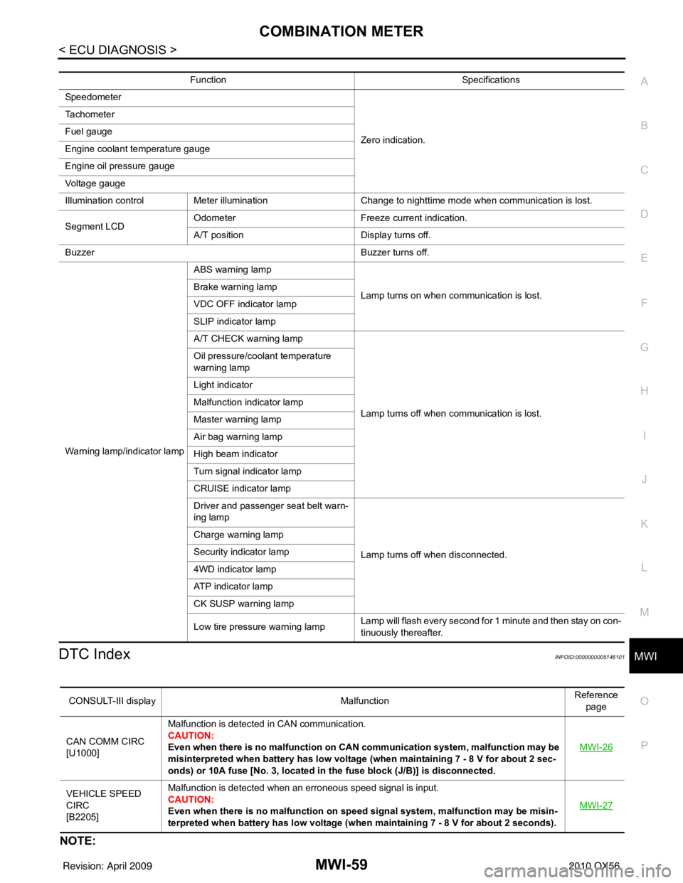
DTC IndexINFOID:0000000005146101
NOTE:
Function Specifications
Speedometer
Zero indication.
Tachometer
Fuel gauge
Engine coolant temperature gauge
Engine oil pressure gauge
Voltage gauge
Illumination control
Meter illumination Change to nighttime mode when communication is lost.
Segment LCD Odometer
Freeze current indication.
A/T position Display turns off.
Buzzer Buzzer turns off.
Warning lamp/indicator lamp ABS warning lamp
Lamp turns on when communication is lost.
Brake warning lamp
VDC OFF indicator lamp
SLIP indicator lamp
A/T CHECK warning lamp
Lamp turns off when communication is lost.
Oil pressure/coolant temperature
warning lamp
Light indicator
Malfunction indicator lamp
Master warning lamp
Air bag warning lamp
High beam indicator
Turn signal indicator lamp
CRUISE indicator lamp
Driver and passenger seat belt warn-
ing lamp
Lamp turns off when disconnected.
Charge warning lamp
Security indicator lamp
4WD indicator lamp
ATP indicator lamp
CK SUSP warning lamp
Low tire pressu
re warning lamp Lamp will flash every second for 1 minute and then stay on con-
tinuously thereafter.
CONSULT-III display
MalfunctionReference
page
CAN COMM CIRC
[U1000] Malfunction is detected in CAN communication.
CAUTION:
Even when there is no ma
lfunction on CAN communication system, malfunction may be
misinterpreted when battery has low voltag e (when maintaining 7 - 8 V for about 2 sec-
onds) or 10A fuse [No. 3, located in the fuse block (J/B)] is disconnected. MWI-26
VEHICLE SPEED
CIRC
[B2205]Malfunction is detected when an erroneous speed signal is input.
CAUTION:
Even when there is no malfunction on speed signal system, malfunction may be misin-
terpreted when battery has low voltage (whe
n maintaining 7 - 8 V for about 2 seconds). MWI-27
Revision: April 20092010 QX56
Page 2822 of 4210
MWI-60
< ECU DIAGNOSIS >
COMBINATION METER
“TIME” indicates the following.
• 0: Indicates that a malfunction is detected at present.
• 1-63: Indicates that a malfunction was detected in the past. (Displays number of ignition switch OFF → ON
cycles after malfunction is detected. Self-diagnos is result is erased when “63” is exceeded.)
Revision: April 20092010 QX56
Page 2837 of 4210

MWI
BCM (BODY CONTROL MODULE)MWI-75
< ECU DIAGNOSIS >
C
DE
F
G H
I
J
K L
M B A
O P
DTC Inspection Priority ChartINFOID:0000000005380662
If some DTCs are displayed at the same time, perform inspections one by one based on the following priority
chart.
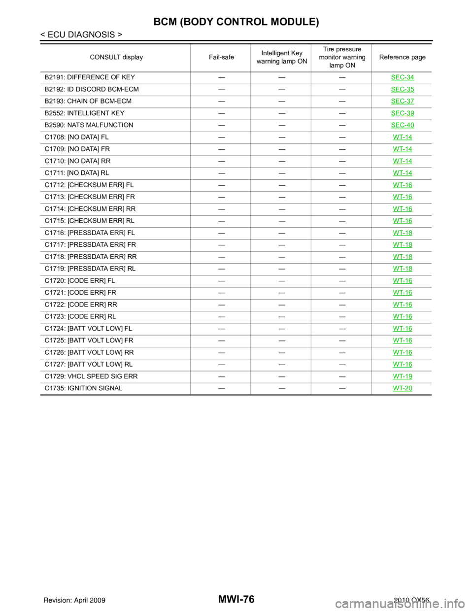
DTC IndexINFOID:0000000005380663
NOTE: Details of time display
• CRNT: Displays when there is a malfunction now or after returning to the normal condition until turning igni- tion switch OFF → ON again.
• 1 - 39: Displayed if any previous ma lfunction is present when current conditi on is normal. It increases like 1
→ 2 → 3...38 → 39 after returning to the normal condition whenever ignition switch OFF → ON. The counter
remains at 39 even if the number of cycles exceeds it. It is counted from 1 again when turning ignition switch
OFF → ON after returning to the normal condi tion if the malfunction is detected again.
Display contents of CONSULT Fail-safe Cancellation
U1000: CAN COMM CIRCUIT I nhibit engine crankingWhen the BCM re-establishes communication with the other mod-
ules.
Priority
DTC
1 • U1000: CAN COMM CIRCUIT
2 • B2190: NATS ANTENNA AMP
• B2191: DIFFERENCE OF KEY
• B2192: ID DISCORD BCM-ECM
• B2193: CHAIN OF BCM-ECM
• B2013: STRG COMM 1
• B2552: INTELLIGENT KEY
• B2590: NATS MALFUNCTION
3 • C1729: VHCL SPEED SIG ERR
• C1735: IGNITION SIGNAL
4 • C1708: [NO DATA] FL
• C1709: [NO DATA] FR
• C1710: [NO DATA] RR
• C1711: [NO DATA] RL
• C1712: [CHECKSUM ERR] FL
• C1713: [CHECKSUM ERR] FR
• C1714: [CHECKSUM ERR] RR
• C1715: [CHECKSUM ERR] RL
• C1716: [PRESSDATA ERR] FL
• C1717: [PRESSDATA ERR] FR
• C1718: [PRESSDATA ERR] RR
• C1719: [PRESSDATA ERR] RL
• C1720: [CODE ERR] FL
• C1721: [CODE ERR] FR
• C1722: [CODE ERR] RR
• C1723: [CODE ERR] RL
• C1724: [BATT VOLT LOW] FL
• C1725: [BATT VOLT LOW] FR
• C1726: [BATT VOLT LOW] RR
• C1727: [BATT VOLT LOW] RL
CONSULT display
Fail-safeIntelligent Key
warning lamp ON Tire pressure
monitor warning lamp ON Reference page
No DTC is detected.
further testing
may be required. ————
U1000: CAN COMM CIRCUIT ———BCS-32
B2190: NATS ANTENNA AMP ———SEC-31
Revision: April 20092010 QX56
Page 2838 of 4210

MWI-76
< ECU DIAGNOSIS >
BCM (BODY CONTROL MODULE)
B2191: DIFFERENCE OF KEY———SEC-34
B2192: ID DISCORD BCM-ECM ———SEC-35
B2193: CHAIN OF BCM-ECM ———SEC-37
B2552: INTELLIGENT KEY ———SEC-39
B2590: NATS MALFUNCTION ———SEC-40
C1708: [NO DATA] FL ———WT-14
C1709: [NO DATA] FR ———WT-14
C1710: [NO DATA] RR ———WT-14
C1711: [NO DATA] RL ———WT-14
C1712: [CHECKSUM ERR] FL ———WT-16
C1713: [CHECKSUM ERR] FR ———WT-16
C1714: [CHECKSUM ERR] RR ———WT-16
C1715: [CHECKSUM ERR] RL ———WT-16
C1716: [PRESSDATA ERR] FL ———WT-18
C1717: [PRESSDATA ERR] FR ———WT-18
C1718: [PRESSDATA ERR] RR ———WT-18
C1719: [PRESSDATA ERR] RL ———WT-18
C1720: [CODE ERR] FL ———WT-16
C1721: [CODE ERR] FR ———WT-16
C1722: [CODE ERR] RR ———WT-16
C1723: [CODE ERR] RL ———WT-16
C1724: [BATT VOLT LOW] FL ———WT-16
C1725: [BATT VOLT LOW] FR ———WT-16
C1726: [BATT VOLT LOW] RR ———WT-16
C1727: [BATT VOLT LOW] RL ———WT-16
C1729: VHCL SPEED SIG ERR ———WT-19
C1735: IGNITION SIGNAL ———WT-20
CONSULT display Fail-safeIntelligent Key
warning lamp ON Tire pressure
monitor warning
lamp ON Reference page
Revision: April 20092010 QX56