2010 INFINITI QX56 display
[x] Cancel search: displayPage 2643 of 4210
![INFINITI QX56 2010 Factory Service Manual LAN
CAN COMMUNICATION SYSTEMLAN-45
< FUNCTION DIAGNOSIS > [CAN]
C
D
E
F
G H
I
J
K L
B A
O P
N
Engine speed signal
T RRR R R R R R
Engine status signal TR
Fuel consumption monitor signal TR
RT
ICC stee INFINITI QX56 2010 Factory Service Manual LAN
CAN COMMUNICATION SYSTEMLAN-45
< FUNCTION DIAGNOSIS > [CAN]
C
D
E
F
G H
I
J
K L
B A
O P
N
Engine speed signal
T RRR R R R R R
Engine status signal TR
Fuel consumption monitor signal TR
RT
ICC stee](/manual-img/42/57032/w960_57032-2642.png)
LAN
CAN COMMUNICATION SYSTEMLAN-45
< FUNCTION DIAGNOSIS > [CAN]
C
D
E
F
G H
I
J
K L
B A
O P
N
Engine speed signal
T RRR R R R R R
Engine status signal TR
Fuel consumption monitor signal TR
RT
ICC steering switch signal TR
Malfunction indicator lamp signal T R
Wide open throttle position signal T R
A/T CHECK indicato r lamp signal T R
A/T fluid temperature sensor signal T R
A/T position indicator lamp signal TR RR
A/T self-diagnosis signal R T
Current gear position signal TR R
Input speed signal R TR
Output shaft revolution signal R TR R
P range signal TR R RR
ICC sensor signal T R
Buzzer output signal TR
TR
ICC OD cancel request signal R RT
ICC operation signal R RT
ICC system display signal TR
System setting signal TRT
RTR
A/C switch/indicator signal TR
RT
A/C switch signal RT R
Blower fan motor switch signal RT
Day time running light request signal TR R
Door lock/unlock status signal TR
Door switch signal R R TR R R
Front fog light request signal TR
Front wiper request signal RT R
High beam request signal TR R
Horn chirp signal TR
Ignition switch signal RTR R
Key fob door unlock signal RT
Key fob ID signal RT
Key switch signal RT
Low beam request signal TR
Position light request signal TR R
Rear window defogger switch signal T RR
Sleep wake up signal RT R R
Theft warning horn request signal TR
Signal name/Connecting unit
ECM
TCM
LASER ICC
ADP AV
BCM
HVAC I-KEY M&A
STRG 4WD
ABS
IPDM-E
Revision: April 20092010 QX56
Page 2647 of 4210
![INFINITI QX56 2010 Factory Service Manual LAN
TROUBLE DIAGNOSISLAN-49
< FUNCTION DIAGNOSIS > [CAN]
C
D
E
F
G H
I
J
K L
B A
O P
N
NOTE:
Replace the unit when “NG” is indicated on the “INITIAL DIAG”.
A/C Auto Amp.
0: Error at present, 1 INFINITI QX56 2010 Factory Service Manual LAN
TROUBLE DIAGNOSISLAN-49
< FUNCTION DIAGNOSIS > [CAN]
C
D
E
F
G H
I
J
K L
B A
O P
N
NOTE:
Replace the unit when “NG” is indicated on the “INITIAL DIAG”.
A/C Auto Amp.
0: Error at present, 1](/manual-img/42/57032/w960_57032-2646.png)
LAN
TROUBLE DIAGNOSISLAN-49
< FUNCTION DIAGNOSIS > [CAN]
C
D
E
F
G H
I
J
K L
B A
O P
N
NOTE:
Replace the unit when “NG” is indicated on the “INITIAL DIAG”.
A/C Auto Amp.
0: Error at present, 1 – 39: Error in the past (Number means the number of times the ignition switch is turned OFF→
ON)
*: 39 or higher number is fixed at 39 until the self-diagnosis result is erased.
Intelligent Key Unit
0: Error at present, 1 – 39: Error in the past (Number means the number of times the ignition switch is turned OFF→ON)
*: 39 or higher number is fixed at 39 until the self-diagnosis result is erased.
Combination Meter
ITEMCAN DIAG SUP-
PORT MNTR DescriptionNormal Error
PRSNT
BCM INITIAL DIAG Status of CAN controller
OKNG
TRANSMIT DIAG Signal transmission status
UNKWN
ECM Signal receiving status from the ECM
IPDM E/R Signal receiving status from the IPDM E/R
METER/M&A Signal receiving status from the combination meter
I-KEY Not used even though indicated
ITEM
CAN DIAG SUP-
PORT MNTR Description Normal
Error
PRSNT PAST PRSNT PAST
HVAC TRANSMIT DIAG Signal transmission status
OKOK
or
1 – 39
*UNKWN 0
ECM Signal receiving status from the ECM
TCM Not used even though indicated
BCM/SEC Signal receiving status from the BCM OKOK
or
1 – 39
*UNKWN 0
VDC/TCS/ABS Signal receivin
g status from the ABS actua-
tor and electric unit (control unit)
IPDM E/R Not used even though indicated
DISPLAY Signal receiving status from the AV control
unit
OKOK
or
1 – 39
*UNKWN 0
I-KEY
Not used even though indicated
EPS
AWD/4WD
e4WD
ICC
LANE CAMERA
TIRE-P
ITEM
CAN DIAG SUP-
PORT MNTR Description Normal
Error
PRSNT PAST PRSNT PAST
I-KEY TRANSMIT DIAG Signal transmission status
OKOK
or
1 – 39
*UNKWN 0
ECM
Signal receiving status from the ECM
METER/M&A Signal receiving status from the combina-
tion meter
BCM/SEC Signal receiving status from the BCM
Revision: April 20092010 QX56
Page 2648 of 4210
![INFINITI QX56 2010 Factory Service Manual LAN-50
< FUNCTION DIAGNOSIS >[CAN]
TROUBLE DIAGNOSIS
0: Error at present, 1 – 39: Error in the past (Number m
eans the number of times the ignition switch is turned OFF →ON)
*: 39 or higher number INFINITI QX56 2010 Factory Service Manual LAN-50
< FUNCTION DIAGNOSIS >[CAN]
TROUBLE DIAGNOSIS
0: Error at present, 1 – 39: Error in the past (Number m
eans the number of times the ignition switch is turned OFF →ON)
*: 39 or higher number](/manual-img/42/57032/w960_57032-2647.png)
LAN-50
< FUNCTION DIAGNOSIS >[CAN]
TROUBLE DIAGNOSIS
0: Error at present, 1 – 39: Error in the past (Number m
eans the number of times the ignition switch is turned OFF →ON)
*: 39 or higher number is fixed at 39 until the self-diagnosis result is erased.
Transfer Control Unit
0: Error at present, 1 – 39: Error in the past (Number m eans the number of times the ignition switch is turned OFF →ON)
*: 39 or higher number is fixed at 39 until the self-diagnosis result is erased.
ABS Actuator and Electric Unit (Control Unit)
CAUTION:ITEM
CAN DIAG SUP-
PORT MNTR Description Normal
Error
PRSNT PAST PRSNT PAST
M&A TRANSMIT DIAG Signal transmission status
OKOK
or
1 – 39
*UNKWN 0
ECM
Signal receiving status from the ECM
TCM Signal receiving status from the TCM
BCM/SEC Signal receiving status from the BCM
VDC/TCS/ABS Signal receiving stat
us from the ABS actua-
tor and electric unit (control unit)
IPDM E/R Signal receiving status from the IPDM E/R
DISPLAY Not used even though indicated
I-KEY Signal receiving status from the Intelligent
Key unit
OKOK
or
1 – 39
*UNKWN 0
EPS Not used even though indicated
AWD/4WD
e4WD
ICC Signal receiving status from the ICC unit OK OK
or
1 – 39
*UNKWN 0
LANE CAMERA Not used even though indicated
TIRE-P
ITEM CAN DIAG SUP-
PORT MNTR Description Normal
Error
PRSNT PAST PRSNT PAST
4WD TRANSMIT DIAG Signal transmission status
OKOK
or
1 – 39
*UNKWN 0
ECM
Signal receiving status from the ECM
VDC/TCS/ABS Signal receiving stat
us from the ABS actua-
tor and electric unit (control unit)
TCM Signal receiving status from the TCM
STRG Signal receiving status from the steering an-
gle sensor
ITEMCAN DIAG SUP-
PORT MNTR DescriptionNormal Error
PRSNT
ABS INITIAL DIAG Status of CAN controller
OKNG
Caution
TRANSMIT DIAG Signal transmission status
UNKWN
ECM Signal receiving status from the ECM
TCM Signal receiving status from the TCM
METER/M&A Not used even though indicated
STRG Signal receiving status from the steering angle sensor
OK UNKWN
ICC Signal receiving status from the ICC unit
AWD/4WD Signal receiving status from the transfer control unit
Revision: April 20092010 QX56
Page 2764 of 4210

MWI-2
INFORMATION DISPLAY .........................................19
INFORMATION DISPLAY : System Diagram .........20
INFORMATION DISPLAY : System Description ....20
INFORMATION DISPLAY : Component Parts Lo-
cation ................................................................... ...
21
INFORMATION DISPLAY : Component Descrip-
tion ....................................................................... ...
21
DIAGNOSIS SYSTEM (METER) .......................22
Diagnosis Description .......................................... ...22
CONSULT-III Function (METER/M&A) ................ ...23
COMPONENT DIAGNOSIS ........................26
DTC U1000 CAN COMMUNICATION ............ ...26
DTC Logic ............................................................ ...26
Diagnosis Procedure .............................................26
DTC B2205 VEHICLE SPEED CIRCUIT ...........27
Description ........................................................... ...27
DTC Logic ...............................................................27
Diagnosis Procedure .............................................27
POWER SUPPLY AND GROUND CIRCUIT .....28
COMBINATION METER ........................................ ...28
COMBINATION METER : Diagnosis Procedure ....28
BCM (BODY CONTROL MODULE) ...................... ...29
BCM (BODY CONTROL MODULE) : Diagnosis
Procedure ...............................................................
29
IPDM E/R (INTELLIGENT POWER DISTRIBU-
TION MODULE ENGINE ROOM) .......................... ...
30
IPDM E/R (INTELLIGENT POWER DISTRIBU-
TION MODULE ENGINE ROOM) : Diagnosis Pro-
cedure .....................................................................
30
FUEL LEVEL SENSOR SIGNAL CIRCUIT .......32
Description ........................................................... ...32
Component Function Check ...................................32
Diagnosis Procedure .............................................32
Component Inspection ............................................33
OIL PRESSURE SWITCH SIGNAL CIRCUIT ...34
Description ..............................................................34
Component Function Check ...................................34
Diagnosis Procedure ..............................................34
Component Inspection ............................................34
PARKING BRAKE SWITCH SIGNAL CIR-
CUIT ...................................................................
35
Description ........................................................... ...35
Component Function Check ...................................35
Diagnosis Procedure ..............................................35
Component Inspection ............................................35
WASHER LEVEL SWITCH SIGNAL CIRCUIT ...36
Description ........................................................... ...36
Diagnosis Procedure ..............................................36
Component Inspection ............................................36
CLOCK ..............................................................37
Wiring Diagram .................................................... ...37
ECU DIAGNOSIS .......................................39
COMBINATION METER ................................. ...39
Reference Value .................................................. ...39
Wiring Diagram .......................................................41
Fail Safe ..................................................................58
DTC Index ...............................................................59
BCM (BODY CONTROL MODULE) ..................61
Reference Value .................................................. ...61
Terminal Layout ......................................................64
Physical Values .......................................................64
Wiring Diagram .......................................................70
Fail Safe .................................................................74
DTC Inspection Priority Chart ...............................75
DTC Index ..............................................................75
IPDM E/R (INTELLIGENT POWER DISTRI-
BUTION MODULE ENGINE ROOM) .................
77
Reference Value .................................................. ...77
Terminal Layout ......................................................79
Physical Values .......................................................80
Wiring Diagram .......................................................85
Fail Safe .................................................................88
DTC Index ..............................................................90
SYMPTOM DIAGNOSIS ............................91
THE FUEL GAUGE POINTER DOES NOT
MOVE .............................................................. ...
91
Description ........................................................... ...91
Diagnosis Procedure ...............................................91
THE FUEL GAUGE POINTER DOES NOT
MOVE TO "F" WHEN REFUELING ..................
92
Description ........................................................... ...92
Diagnosis Procedure ...............................................92
THE OIL PRESSURE WARNING LAMP
DOES NOT TURN ON .................................... ...
93
Description ........................................................... ...93
Diagnosis Procedure ...............................................93
THE OIL PRESSURE WARNING LAMP
DOES NOT TURN OFF .................................. ...
94
Description ........................................................... ...94
Diagnosis Procedure ...............................................94
THE PARKING BRAKE RELEASE WARNING
CONTINUES DISPLAYING, OR DOES NOT
DISPLAY ............................................................
95
Description ........................................................... ...95
Diagnosis Procedure ...............................................95
THE LOW WASHER FLUID WARNING CON-
TINUES DISPLAYING, or DOES NOT DIS-
PLAY ..................................................................
96
Revision: April 20092010 QX56
Page 2765 of 4210

MWI
MWI-3
C
DE
F
G H
I
J
K L
M B
A
O P
Description ..........................................................
....
96
Diagnosis Procedure ...............................................96
THE DOOR OPEN WARNING CONTINUES
DISPLAYING, OR DOES NOT DISPLAY ..........
97
Description .......................................................... ....97
Diagnosis Procedure ...............................................97
PRECAUTION ..............................................98
PRECAUTIONS .............................................. ....98
Precaution for Supplemental Restraint System
(SRS) "AIR BAG" and "SEAT BELT PRE-TEN-
SIONER" ............................................................. ....
98
Precaution Necessary for Steering Wheel Rota-
tion After Battery Disconnect ...................................
98
ON-VEHICLE REPAIR ...............................100
COMBINATION METER .................................100
Removal and Installation ..................................... ..100
CLOCK ............................................................101
Removal and Installation .......................................101
Revision: April 20092010 QX56
Page 2767 of 4210

MWI
METER SYSTEMMWI-5
< FUNCTION DIAGNOSIS >
C
DE
F
G H
I
J
K L
M B A
O P
FUNCTION DIAGNOSIS
METER SYSTEM
METER SYSTEM
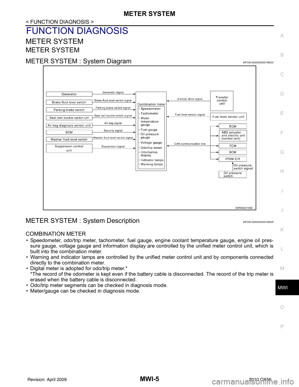
METER SYSTEM : System DiagramINFOID:0000000005146025
METER SYSTEM : System DescriptionINFOID:0000000005146026
COMBINATION METER
• Speedometer, odo/trip meter, tachometer, fuel gauge, engine coolant temperature gauge, engine oil pres-
sure gauge, voltage gauge and information display are controlled by the unified meter control unit, which is
built into the combination meter.
• Warning and indicator lamps are controlled by the unified meter control unit and by components connected directly to the combination meter.
• Digital meter is adopted for odo/trip meter.* *The record of the odometer is kept even if the battery cable is disconnected. The record of the trip meter is
erased when the battery cable is disconnected.
• Odo/trip meter segments can be checked in diagnosis mode.
• Meter/gauge can be checked in diagnosis mode.
AWNIA0274GB
Revision: April 20092010 QX56
Page 2769 of 4210

MWI
METER SYSTEMMWI-7
< FUNCTION DIAGNOSIS >
C
DE
F
G H
I
J
K L
M B A
O P
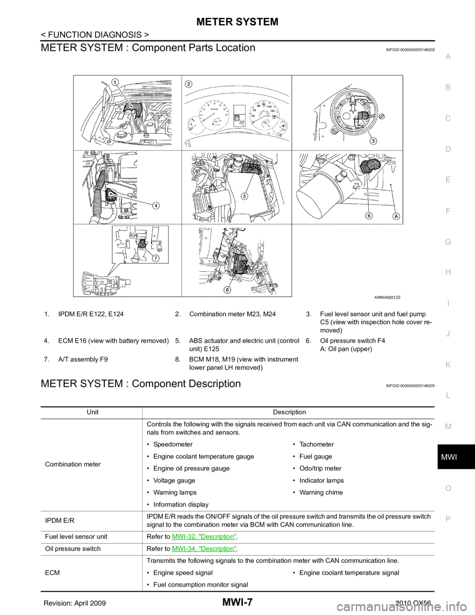
METER SYSTEM : Com ponent Parts LocationINFOID:0000000005146028
METER SYSTEM : Component DescriptionINFOID:0000000005146029
1. IPDM E/R E122, E124 2. Combination meter M23, M24 3. Fuel level sensor unit and fuel pump
C5 (view with inspection hole cover re-
moved)
4. ECM E16 (view with battery removed) 5. ABS actuator and electric unit (control unit) E1256. Oil pressure switch F4
A: Oil pan (upper)
7. A/T assembly F9 8. BCM M18, M19 (view with instrument
lower panel LH removed)
AWNIA0201ZZ
Unit Description
Combination meter Controls the following with the signals received from each unit via CAN communication and the sig-
nals from switches and sensors.
• Speedometer
• Tachometer
• Engine coolant temperature gauge • Fuel gauge
• Engine oil pressure gauge • Odo/trip meter
• Voltage gauge • Indicator lamps
• Warning lamps • Warning chime
• Information display
IPDM E/R IPDM E/R reads the ON/OFF signals of the oil pressure switch and transmits the oil pressure switch
signal to the combination meter via BCM with CAN communication line.
Fuel level sensor unit Refer to MWI-32, "
Description".
Oil pressure switch Refer to MWI-34, "
Description".
ECM Transmits the following signals to the combination meter with CAN communication line.
• Engine speed signal
• Engine coolant temperature signal
• Fuel consumption monitor signal
Revision: April 20092010 QX56
Page 2775 of 4210

MWI
METER SYSTEMMWI-13
< FUNCTION DIAGNOSIS >
C
DE
F
G H
I
J
K L
M B A
O PFUEL GAUGE : Component DescriptionINFOID:0000000005146045
ENGINE OIL PRESSURE GAUGE
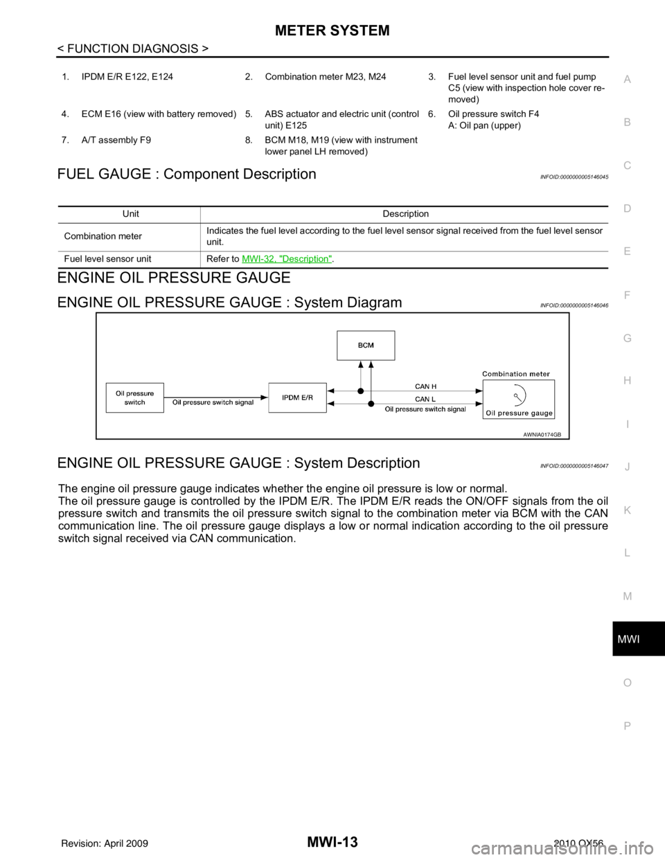
ENGINE OIL PRESSURE GAUGE : System DiagramINFOID:0000000005146046
ENGINE OIL PRESSURE GAUGE : System DescriptionINFOID:0000000005146047
The engine oil pressure gauge indicates whether the engine oil pressure is low or normal.
The oil pressure gauge is controlled by the IPDM E/R. The IPDM E/R reads the ON /OFF signals from the oil
pressure switch and transmits the oil pressure switch signal to the combination meter via BCM with the CAN
communication line. The oil pressure gauge displays a low or normal indication according to the oil pressure
switch signal received via CAN communication.
1. IPDM E/R E122, E124 2. Combination meter M23, M24 3. Fuel level sensor unit and fuel pump
C5 (view with inspection hole cover re-
moved)
4. ECM E16 (view with battery removed) 5. ABS actuator and electric unit (control unit) E1256. Oil pressure switch F4
A: Oil pan (upper)
7. A/T assembly F9 8. BCM M18, M19 (view with instrument
lower panel LH removed)
Unit Description
Combination meter Indicates the fuel level according to the fuel level sensor signal received from the fuel level sensor
unit.
Fuel level sensor unit Refer to MWI-32, "
Description".
AWNIA0174GB
Revision: April 20092010 QX56