2010 INFINITI QX56 fuse diagram
[x] Cancel search: fuse diagramPage 1754 of 4210
![INFINITI QX56 2010 Factory Service Manual FUEL PUMPEC-401
< COMPONENT DIAGNOSIS > [VK56DE]
C
D
E
F
G H
I
J
K L
M A
EC
NP
O
2. Disconnect 15 A fuse.
3. Check 15 A fuse (No. 48).
OK or NG
OK >> GO TO 7.
NG >> Replace fuse.
7.CHECK CONDENSER-2 P INFINITI QX56 2010 Factory Service Manual FUEL PUMPEC-401
< COMPONENT DIAGNOSIS > [VK56DE]
C
D
E
F
G H
I
J
K L
M A
EC
NP
O
2. Disconnect 15 A fuse.
3. Check 15 A fuse (No. 48).
OK or NG
OK >> GO TO 7.
NG >> Replace fuse.
7.CHECK CONDENSER-2 P](/manual-img/42/57032/w960_57032-1753.png)
FUEL PUMPEC-401
< COMPONENT DIAGNOSIS > [VK56DE]
C
D
E
F
G H
I
J
K L
M A
EC
NP
O
2. Disconnect 15 A fuse.
3. Check 15 A fuse (No. 48).
OK or NG
OK >> GO TO 7.
NG >> Replace fuse.
7.CHECK CONDENSER-2 POWER SUPPLY
CIRCUIT-II FOR OPEN AND SHORT
1. Disconnect IPDM E/R harness connector E119.
2. Check harness continuity between IPDM E/R terminal 13 and condenser-2 terminal 1. Refer to Wiring Diagram.
3. Also check harness for short to ground and short to power.
OK or NG
OK >> GO TO 13.
NG >> Repair open circuit or short to ground or short to power in harness or connectors.
8.CHECK CONDENSER-2 GROUND CIRCUIT FOR OPEN AND SHORT
1. Check harness continuity between condenser-2 terminal 2 and ground. Refer to Wiring Diagram.
2. Also check harness for short to power.
OK or NG
OK >> GO TO 9.
NG >> Repair open circuit or short to power in harness or connectors.
9.CHECK CONDENSER-2
Refer to EC-402, "
Component Inspection".
OK or NG
OK >> GO TO 10.
NG >> Replace condenser-2.
10.CHECK FUEL PUMP POWER SUPPLY AND GROUND CIRCUIT FOR OPEN AND SHORT
1. Turn ignition switch OFF.
2. Disconnect “fuel level sensor unit and fuel pump” harness con- nector.
3. Disconnect IPDM E/R harness connector E119.
4. Check harness continuity between IPDM E/R terminal 13 and
“fuel level sensor unit and fuel pump” terminal 1, “fuel level sen-
sor unit and fuel pump” terminal 3 and ground.
Refer to Wiring Diagram.
5. Also check harness for short to ground and short to power.
OK or NG
OK >> GO TO 12.
NG >> GO TO 11.
11 .DETECT MALFUNCTIONING PART
Check the following.
• Harness connectors E41, C1
• Harness for open or short between fuel pump and IPDM E/R
• Harness for open or short between fuel pump and ground
>> Repair open circuit or short to ground or short to power in harness or connectors.
Continuity should exist.
Continuity should exist.
Continuity should exist.
BBIA0583E
Revision: April 20092010 QX56
Page 1757 of 4210
![INFINITI QX56 2010 Factory Service Manual EC-404
< COMPONENT DIAGNOSIS >[VK56DE]
ICC BRAKE SWITCH
4. Check voltage between ICC brake switch terminal 1 and ground
with CONSULT-III or tester.
OK or NG
OK >> GO TO 6.
NG >> GO TO 3.
3.CHECK ICC B INFINITI QX56 2010 Factory Service Manual EC-404
< COMPONENT DIAGNOSIS >[VK56DE]
ICC BRAKE SWITCH
4. Check voltage between ICC brake switch terminal 1 and ground
with CONSULT-III or tester.
OK or NG
OK >> GO TO 6.
NG >> GO TO 3.
3.CHECK ICC B](/manual-img/42/57032/w960_57032-1756.png)
EC-404
< COMPONENT DIAGNOSIS >[VK56DE]
ICC BRAKE SWITCH
4. Check voltage between ICC brake switch terminal 1 and ground
with CONSULT-III or tester.
OK or NG
OK >> GO TO 6.
NG >> GO TO 3.
3.CHECK ICC BRAKE SWITCH POWER SUPPLY CIRCUIT-II
1. Turn ignition switch OFF.
2. Disconnect ICC brake hold relay.
3. Check harness continuity between ICC brake switch terminal 1 and ICC brake hold relay terminal 3.
Refer to Wiring Diagram
OK or NG
OK >> GO TO 4.
NG >> Repair open circuit or short to ground or short to power in harness or connectors.
4.CHECK ICC BRAKE HOLD RE LAY POWER SUPPLY CIRCUIT
1. Turn ignition switch ON.
2. Check the voltage between ICC brake hold relay terminal 4 and ground with CONSULT-III or tester.
OK or NG
OK >> GO TO 8.
NG >> GO TO 5.
5.DETECT MALFUNCTIONING PART
Check the following.
• Harness connectors M31, E152
• Fuse block (J/B) connector M4
• 10 A fuse (No.15)
• Harness for open or short between ICC brake hold relay and fuse
>> Repair open circuit or short to ground or short to power in harness or connectors.
6.CHECK ICC BRAKE SWITCH INPUT SIGNAL CIRCUIT FOR OPEN AND SHORTVoltage: Battery voltage
PBIB0857E
BBIA0471E
Continuity should exist.
Voltage: Battery voltage
MBIB0059E
Revision: April 20092010 QX56
Page 2003 of 4210
POWER SUPPLY AND GROUND CIRCUITEXL-27
< COMPONENT DIAGNOSIS >
C
DE
F
G H
I
J
K
M A
B
EXL
N
O P
COMPONENT DIAGNOSIS
POWER SUPPLY AND GROUND CIRCUIT
BCM (BODY CONTROL MODULE)
BCM (BODY CONTROL MODULE) : Diagnosis ProcedureINFOID:0000000005369888
Regarding Wiring Diagram information, refer to BCS-49, "Wiring Diagram".
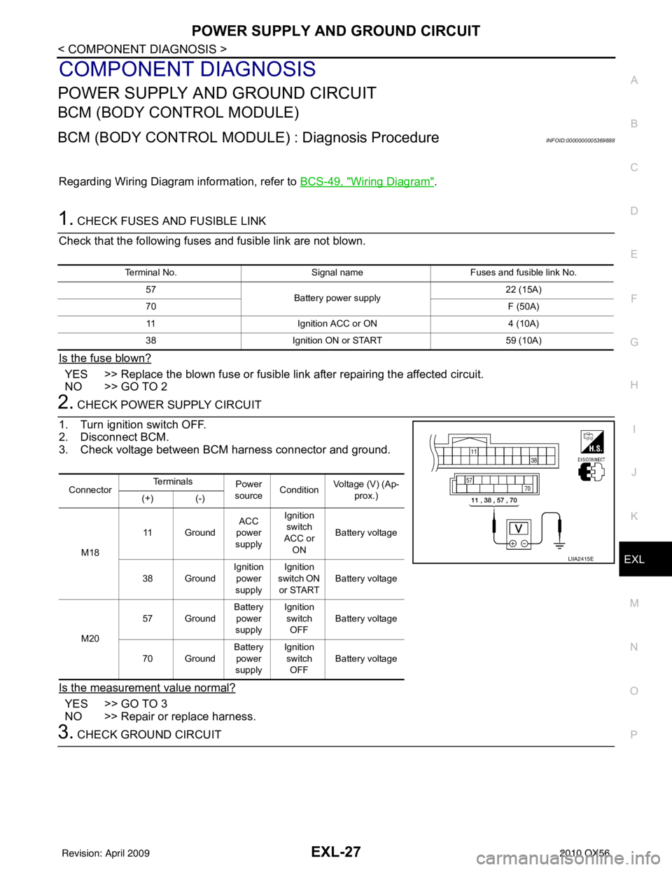
1. CHECK FUSES AND FUSIBLE LINK
Check that the following fuses and fusible link are not blown.
Is the fuse blown?
YES >> Replace the blown fuse or fusible link after repairing the affected circuit.
NO >> GO TO 2
2. CHECK POWER SUPPLY CIRCUIT
1. Turn ignition switch OFF.
2. Disconnect BCM.
3. Check voltage between BCM harness connector and ground.
Is the measurement value normal?
YES >> GO TO 3
NO >> Repair or replace harness.
3. CHECK GROUND CIRCUIT
Terminal No. Signal nameFuses and fusible link No.
57 Battery power supply 22 (15A)
70 F (50A)
11 Ignition ACC or ON 4 (10A)
38 Ignition ON or START 59 (10A)
ConnectorTe r m i n a l s
Power
source Condition Voltage (V) (Ap-
prox.)
(+) (-)
M18 11 Ground
ACC
power
supply Ignition
switch
ACC or ON Battery voltage
38 Ground Ignition
power
supply Ignition
switch ON
or START Battery voltage
M20 57 Ground
Battery
power
supply Ignition
switch OFF Battery voltage
70 Ground Battery
power
supply Ignition
switch OFF Battery voltage
LIIA2415E
Revision: April 20092010 QX56
Page 2004 of 4210
EXL-28
< COMPONENT DIAGNOSIS >
POWER SUPPLY AND GROUND CIRCUIT
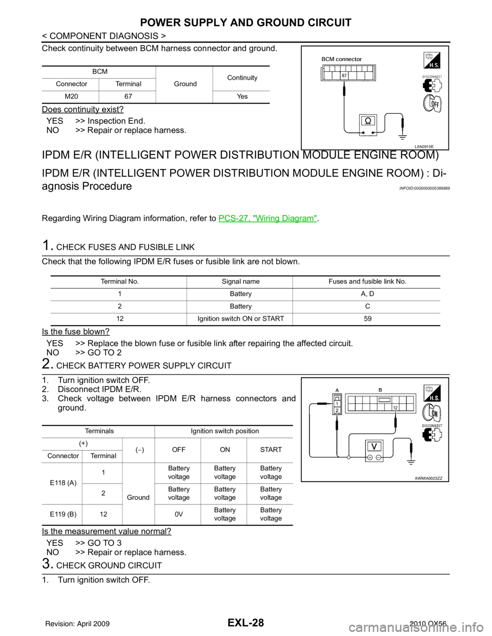
Check continuity between BCM harness connector and ground.
Does continuity exist?
YES >> Inspection End.
NO >> Repair or replace harness.
IPDM E/R (INTELLIGENT POWER DISTRIBUTION MODULE ENGINE ROOM)
IPDM E/R (INTELLIGENT POWER DIST RIBUTION MODULE ENGINE ROOM) : Di-
agnosis Procedure
INFOID:0000000005369889
Regarding Wiring Diagram information, refer to PCS-27, "Wiring Diagram".
1. CHECK FUSES AND FUSIBLE LINK
Check that the following IPDM E/R fuses or fusible link are not blown.
Is the fuse blown?
YES >> Replace the blown fuse or fusible link after repairing the affected circuit.
NO >> GO TO 2
2. CHECK BATTERY POWER SUPPLY CIRCUIT
1. Turn ignition switch OFF.
2. Disconnect IPDM E/R.
3. Check voltage between IPDM E/R harness connectors and ground.
Is the measurement value normal?
YES >> GO TO 3
NO >> Repair or replace harness.
3. CHECK GROUND CIRCUIT
1. Turn ignition switch OFF.
BCM
GroundContinuity
Connector Terminal
M20 67 Yes
LIIA0915E
Terminal No. Signal nameFuses and fusible link No.
1 Battery A, D
2 Battery C
12 Ignition switch ON or START 59
TerminalsIgnition switch position
(+) (−) OFF ON START
Connector Terminal
E118 (A) 1
Ground Battery
voltage Battery
voltage Battery
voltage
2 Battery
voltage Battery
voltage Battery
voltage
E119 (B) 12 0VBattery
voltage Battery
voltage
AWMIA0023ZZ
Revision: April 20092010 QX56
Page 2006 of 4210
EXL-30
< COMPONENT DIAGNOSIS >
HEADLAMP (HI) CIRCUIT
HEADLAMP (HI) CIRCUIT
DescriptionINFOID:0000000005370270
The IPDM E/R (intelligent power distribution module engine room) controls the headlamp LH high and head-
lamp RH high relays based on inputs from the BCM via the CAN communication lines. When the headlamp LH
high and headlamp RH high relays are energized, power flows through fuse\
s 34 and 35, located in the IPDM
E/R. Power then flows to the front combination lamps to the headlamp high beam.
Component Function CheckINFOID:0000000005146640
1.CHECK HEADLAMP (HI) OPERATION
WITHOUT CONSULT-III
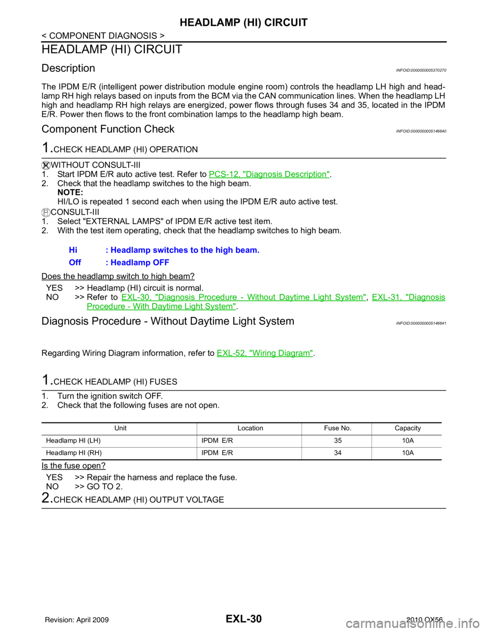
1. Start IPDM E/R auto active test. Refer to PCS-12, "
Diagnosis Description".
2. Check that the headlamp switches to the high beam. NOTE:
HI/LO is repeated 1 second each when usi ng the IPDM E/R auto active test.
CONSULT-III
1. Select "EXTERNAL LAMPS" of IPDM E/R active test item.
2. With the test item operating, check that the headlamp switches to high beam.
Does the headlamp switch to high beam?
YES >> Headlamp (HI) circuit is normal.
NO >> Refer to EXL-30, "
Diagnosis Procedure - Without Daytime Light System", EXL-31, "Diagnosis
Procedure - With Daytime Light System".
Diagnosis Procedure - Wit hout Daytime Light SystemINFOID:0000000005146641
Regarding Wiring Diagram information, refer to EXL-52, "Wiring Diagram".
1.CHECK HEADLAMP (HI) FUSES
1. Turn the ignition switch OFF.
2. Check that the following fuses are not open.
Is the fuse open?
YES >> Repair the harness and replace the fuse.
NO >> GO TO 2.
2.CHECK HEADLAMP (HI) OUTPUT VOLTAGE Hi : Headlamp switches to the high beam.
Off : Headlamp OFF
Unit
LocationFuse No.Capacity
Headlamp HI (LH) IPDM E/R3510A
Headlamp HI (RH) IPDM E/R3410A
Revision: April 20092010 QX56
Page 2007 of 4210
HEADLAMP (HI) CIRCUITEXL-31
< COMPONENT DIAGNOSIS >
C
DE
F
G H
I
J
K
M A
B
EXL
N
O P
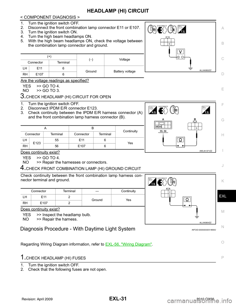
1. Turn the ignition switch OFF.
2. Disconnect the front combination lamp connector E11 or E107.
3. Turn the ignition switch ON.
4. Turn the high beam headlamps ON.
5. With the high beam headlamps ON, check the voltage between the combination lamp connector and ground.
Are the voltage readings as specified?
YES >> GO TO 4.
NO >> GO TO 3.
3.CHECK HEADLAMP (HI) CIRCUIT FOR OPEN
1. Turn the ignition switch OFF.
2. Disconnect IPDM E/R connector E123.
3. Check continuity between the IPDM E/R harness connector (A) and the front combination lamp harness connector (B).
Does continuity exist?
YES >> GO TO 4.
NO >> Repair the harnesses or connectors.
4.CHECK FRONT COMBINATION LAMP (HI) GROUND CIRCUIT
Check continuity between the front combination lamp harness con-
nector terminal and ground.
Does continuity exist?
YES >> Inspect the headlamp bulb.
NO >> Repair the harness.
Diagnosis Procedure - With Daytime Light SystemINFOID:0000000005146642
Regarding Wiring Diagram information, refer to EXL-56, "Wiring Diagram".
1.CHECK HEADLAMP (HI) FUSES
1. Turn the ignition switch OFF.
2. Check that the following fuses are not open.
(+) (−)Voltage
Connector Terminal
LH E11 6 Ground Battery voltage
RH E107 6
ALLIA0852ZZ
AB Continuity
Connector Terminal Connector Terminal
LH E123 55
E11 6
Ye s
RH 56E107 6
AWLIA1371ZZ
Connector Terminal —Continuity
LH E11 2
Ground Yes
RH E107 2
ALLIA0854ZZ
Revision: April 20092010 QX56
Page 2009 of 4210
HEADLAMP (LO) CIRCUITEXL-33
< COMPONENT DIAGNOSIS >
C
DE
F
G H
I
J
K
M A
B
EXL
N
O P
HEADLAMP (LO) CIRCUIT
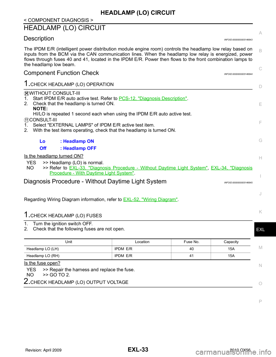
DescriptionINFOID:0000000005146643
The IPDM E/R (intelligent power distribution modul e engine room) controls the headlamp low relay based on
inputs from the BCM via the CAN communication li nes. When the headlamp low relay is energized, power
flows through fuses 40 and 41, located in the IPDM E/R. Power then flows to the front combination lamps to
the headlamp low beam.
Component Function CheckINFOID:0000000005146644
1.CHECK HEADLAMP (LO) OPERATION
WITHOUT CONSULT-III
1. Start IPDM E/R auto active test. Refer to PCS-12, "
Diagnosis Description".
2. Check that the headlamp is turned ON. NOTE:
HI/LO is repeated 1 second each when using the IPDM E/R auto active test.
CONSULT-III
1. Select "EXTERNAL LAMPS" of IPDM E/R active test item.
2. With the test items operating, c heck that the headlamp is turned ON.
Is the headlamp turned ON?
YES >> Headlamp (LO) is normal.
NO >> Refer to EXL-33, "
Diagnosis Procedure - Without Daytime Light System", EXL-34, "Diagnosis
Procedure - With Daytime Light System".
Diagnosis Procedure - Without Daytime Light SystemINFOID:0000000005146645
Regarding Wiring Diagram information, refer to EXL-52, "Wiring Diagram".
1.CHECK HEADLAMP (LO) FUSES
1. Turn the ignition switch OFF.
2. Check that the following fuses are not open.
Is the fuse open?
YES >> Repair the harness and replace the fuse.
NO >> GO TO 2.
2.CHECK HEADLAMP (LO) OUTPUT VOLTAGE Lo : Headlamp ON
Off : Headlamp OFF
Unit
LocationFuse No.Capacity
Headlamp LO (LH) IPDM E/R4015A
Headlamp LO (RH) IPDM E/R4115A
Revision: April 20092010 QX56
Page 2010 of 4210
EXL-34
< COMPONENT DIAGNOSIS >
HEADLAMP (LO) CIRCUIT
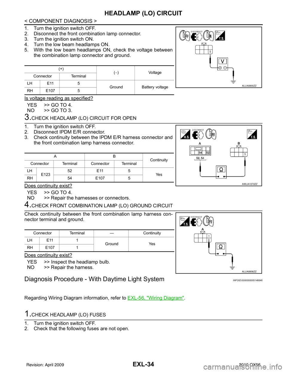
1. Turn the ignition switch OFF.
2. Disconnect the front combination lamp connector.
3. Turn the ignition switch ON.
4. Turn the low beam headlamps ON.
5. With the low beam headlamps ON, check the voltage betweenthe combination lamp connector and ground.
Is voltage reading as specified?
YES >> GO TO 4.
NO >> GO TO 3.
3.CHECK HEADLAMP (LO) CIRCUIT FOR OPEN
1. Turn the ignition switch OFF.
2. Disconnect IPDM E/R connector.
3. Check continuity between the IPDM E/R harness connector and
the front combination lamp harness connector.
Does continuity exist?
YES >> GO TO 4.
NO >> Repair the harnesses or connectors.
4.CHECK FRONT COMBINATION LAMP (LO) GROUND CIRCUIT
Check continuity between the front combination lamp harness con-
nector terminal and ground.
Does continuity exist?
YES >> Inspect the headlamp bulb.
NO >> Repair the harness.
Diagnosis Procedure - With Daytime Light SystemINFOID:0000000005146646
Regarding Wiring Diagram information, refer to EXL-56, "Wiring Diagram".
1.CHECK HEADLAMP (LO) FUSES
1. Turn the ignition switch OFF.
2. Check that the following fuses are not open.
(+) (−)V olt a ge
Connector Terminal
LH E11 5
Ground Battery voltage
RH E107 5
ALLIA0855ZZ
AB
Continuity
Connector Terminal Connector Terminal
LH E123 52
E11 5
Ye s
RH 54E107 5
AWLIA1372ZZ
Connector Terminal —Continuity
LH E11 1
Ground Yes
RH E107 1
ALLIA0856ZZ
Revision: April 20092010 QX56