2010 INFINITI QX56 fuse diagram
[x] Cancel search: fuse diagramPage 2012 of 4210
EXL-36
< COMPONENT DIAGNOSIS >
FRONT FOG LAMP CIRCUIT
FRONT FOG LAMP CIRCUIT
DescriptionINFOID:0000000005146647
The IPDM E/R (intelligent power distribution module engine room) controls the front fog lamp relay based on
inputs from the BCM via the CAN communication lines. When the front fog lamp relay is energized, power
flows from the front fog lamp relay in the IPDM E/R to the front fog lamps.
Component Function CheckINFOID:0000000005146648
1.CHECK FRONT FOG LAMP OPERATION
WITHOUT CONSULT-III
1. Activate IPDM E/R auto active test. Refer to PCS-12, "
Diagnosis Description".
2. Check that the front fog lamp is turned ON.
CONSULT-III
1. Select "EXTERNAL LAMPS" of IPDM E/R active test item.
2. With operating the test items, Check that the front fog lamp is turned ON.
Is the front fog lamp turned ON?
YES >> Front fog lamp circuit is normal.
NO >> Refer to EXL-36, "
Diagnosis Procedure".
Diagnosis ProcedureINFOID:0000000005146649
Regarding Wiring Diagram information, refer to EXL-73, "Wiring Diagram".
1.CHECK FRONT FOG LAMP FUSE
1. Turn the ignition switch OFF.
2. Check that the following fuses are not open.
Is the fuse open?
YES >> Repair the harness and replace the fuse.
NO >> GO TO 2.
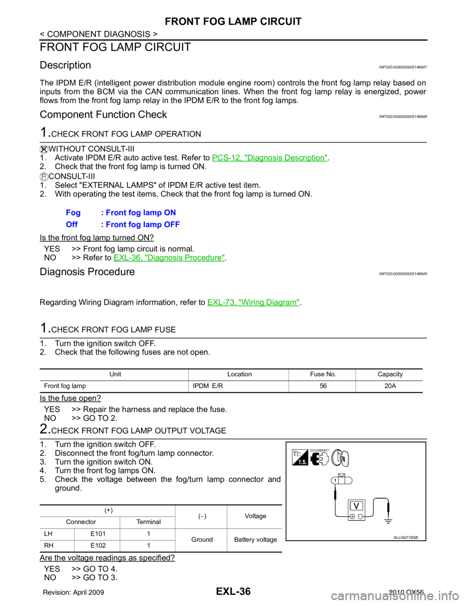
2.CHECK FRONT FOG LAMP OUTPUT VOLTAGE
1. Turn the ignition switch OFF.
2. Disconnect the front fog/turn lamp connector.
3. Turn the ignition switch ON.
4. Turn the front fog lamps ON.
5. Check the voltage between the fog/turn lamp connector and ground.
Are the voltage readings as specified?
YES >> GO TO 4.
NO >> GO TO 3. Fog : Front fog lamp ON
Off : Front fog lamp OFF
Unit
LocationFuse No.Capacity
Front fog lamp IPDM E/R5620A
(+)
(−)V olt a g e
Connector Terminal
LH E101 1
Ground Battery voltage
RH E102 1
ALLIA0719GB
Revision: April 20092010 QX56
Page 2014 of 4210
EXL-38
< COMPONENT DIAGNOSIS >
PARKING LAMP CIRCUIT
PARKING LAMP CIRCUIT
DescriptionINFOID:0000000005146650
The IPDM E/R (intelligent power distribution module engine room) controls the tail lamp relay based on inputs
from the BCM via the CAN communication lines. When the tail lamp relay is energized, power flows through
fuse 37, located in the IPDM E/R. Power then flows to the front and rear combination lamps.
Component Function CheckINFOID:0000000005146651
1.CHECK PARKING LAMP OPERATION
WITHOUT CONSULT-III
1. Activate IPDM E/R auto active test. Refer to PCS-12, "
Diagnosis Description".
2. Check that the parking lamp is turned ON.
CONSULT-III
1. Select "EXTERNAL LAMPS" of IPDM E/R active test item.
2. With operating the test items, check that the parking lamp is turned ON.
Is the parking lamp turned ON?
YES >> Parking lamp circuit is normal.
NO >> Refer to EXL-38, "
Diagnosis Procedure - Without Daytime Light System", EXL-41, "Diagnosis
Procedure - With Daytime Light System".
Diagnosis Procedure - Wit hout Daytime Light SystemINFOID:0000000005146652
Regarding Wiring Diagram information, refer to EXL-84, "Wiring Diagram".
1.CHECK PARKING LAMP FUSES
1. Turn the ignition switch OFF.
2. Check that the following fuses are not open.
Is the fuse open?
YES >> Repair the harness and replace the fuse.
NO >> GO TO 2.
2.CHECK TAIL LAMP RELAY OUTPUT (VOLTAGE)
1. Turn the ignition switch OFF.
2. Disconnect the front combination lamp connector, rear combination lamp connector and license plate
lamp connector.
3. Turn the ignition switch ON.
4. Turn the parking lamps ON. TAIL : Parking lamp ON
Off : Parking lamp OFF
Unit
LocationFuse No.Capacity
Parking lamps IPDM E/R3710A
Revision: April 20092010 QX56
Page 2017 of 4210
PARKING LAMP CIRCUITEXL-41
< COMPONENT DIAGNOSIS >
C
DE
F
G H
I
J
K
M A
B
EXL
N
O P
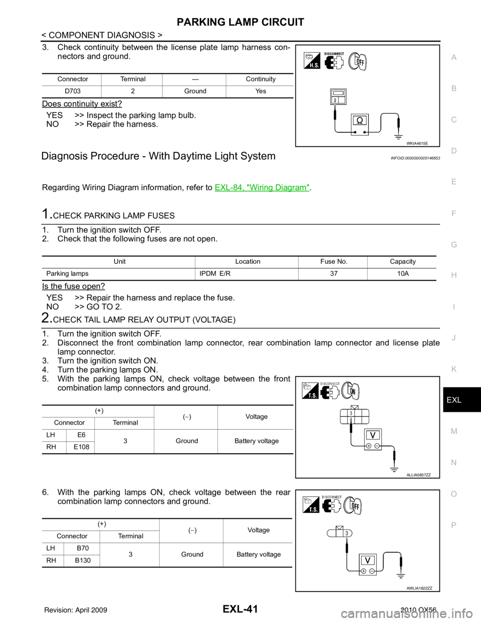
3. Check continuity between the license plate lamp harness con- nectors and ground.
Does continuity exist?
YES >> Inspect the parking lamp bulb.
NO >> Repair the harness.
Diagnosis Procedure - With Daytime Light SystemINFOID:0000000005146653
Regarding Wiring Diagram information, refer to EXL-84, "Wiring Diagram".
1.CHECK PARKING LAMP FUSES
1. Turn the ignition switch OFF.
2. Check that the following fuses are not open.
Is the fuse open?
YES >> Repair the harness and replace the fuse.
NO >> GO TO 2.
2.CHECK TAIL LAMP RELAY OUTPUT (VOLTAGE)
1. Turn the ignition switch OFF.
2. Disconnect the front combination lamp connector, rear combination lamp connector and license plate
lamp connector.
3. Turn the ignition switch ON.
4. Turn the parking lamps ON.
5. With the parking lamps ON, check voltage between the front combination lamp connectors and ground.
6. With the parking lamps ON, check voltage between the rear combination lamp connectors and ground.
Connector Terminal —Continuity
D703 2Ground Yes
WKIA4615E
Unit LocationFuse No.Capacity
Parking lamps IPDM E/R3710A
(+)
(−)V olt a g e
Connector Terminal
LH E6 3Ground Battery voltage
RH E108
ALLIA0857ZZ
(+) (−)V olt a g e
Connector Terminal
LH B70 3Ground Battery voltage
RH B130
AWLIA1622ZZ
Revision: April 20092010 QX56
Page 2234 of 4210
HOW TO READ WIRING DIAGRAMSGI-11
< HOW TO USE THIS MANUAL >
C
DE
F
G H
I
J
K L
M B
GI
N
O P
DescriptionINFOID:0000000005149578
SWITCH POSITIONS
Switches are shown in wiring diagrams as if the vehicle is in the “normal” condition.
A vehicle is in the “normal” condition when:
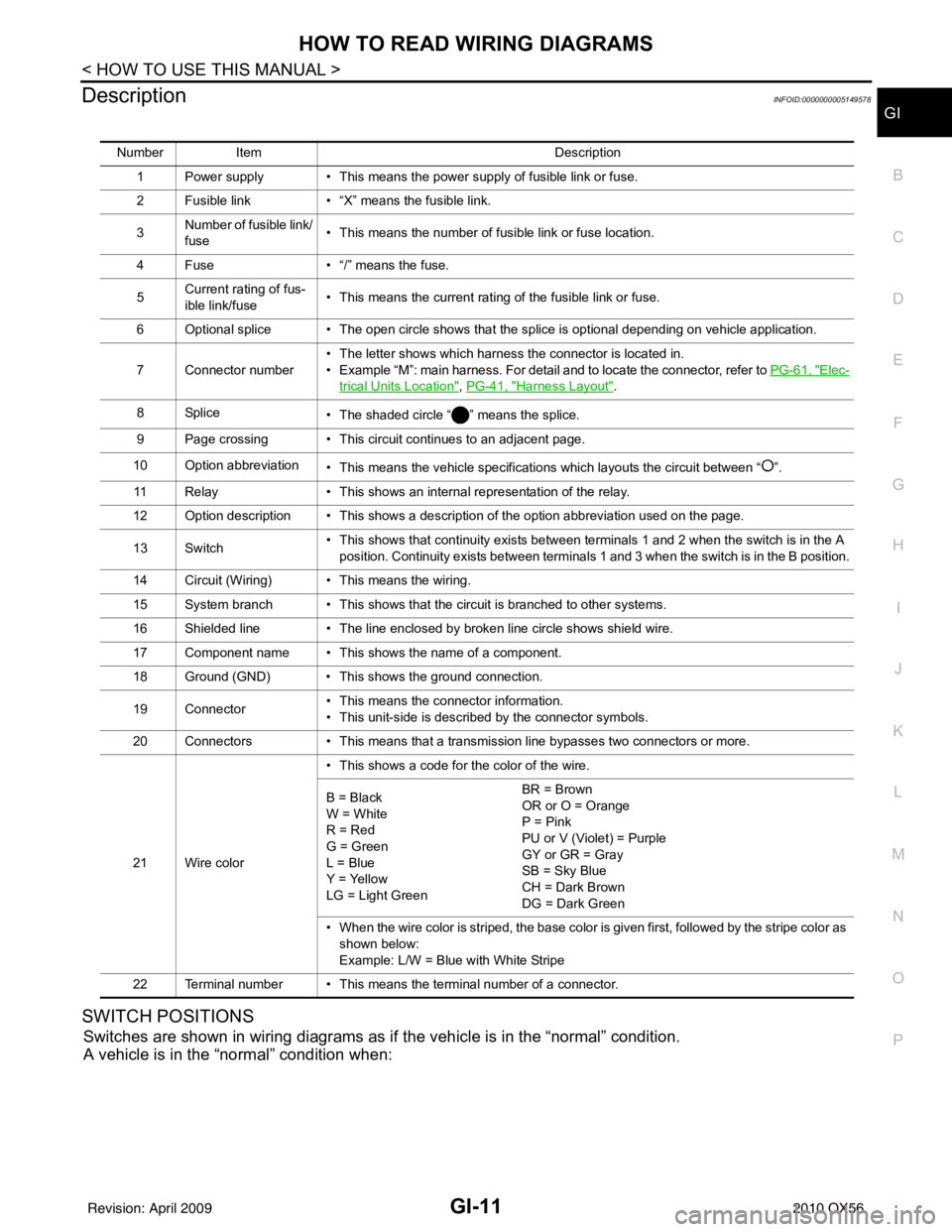
Number Item Description
1 Power supply • This means the power supply of fusible link or fuse.
2 Fusible link • “X” means the fusible link.
3 Number of fusible link/
fuse • This means the number of fusible link or fuse location.
4 Fuse • “/” means the fuse.
5 Current rating of fus-
ible link/fuse • This means the current rating of the fusible link or fuse.
6 Optional splice • The open circle shows that the splice is optional depending on vehicle application.
7 Connector number • The letter shows which harness the connector is located in.
• Example “M”: main harness. For detail and to locate the connector, refer to
PG-61, "
Elec-
trical Units Location", PG-41, "Harness Layout".
8Splice • The shaded circle “ ” means the splice.
9 Page crossing • This circuit continues to an adjacent page.
10 Option abbreviation • This means the vehicle specifications which layouts the circuit between “ ”.
11 Relay • This shows an internal representation of the relay.
12 Option description • This shows a description of the option abbreviation used on the page.
13 Switch • This shows that continuity exists between terminals 1 and 2 when the switch is in the A
position. Continuity exists between terminals 1 and 3 when the switch is in the B position.
14 Circuit (Wiring) • This means the wiring.
15 System branch • This shows that the circuit is branched to other systems.
16 Shielded line • The line enclosed by broken line circle shows shield wire.
17 Component name • This shows the name of a component.
18 Ground (GND) • This shows the ground connection.
19 Connector • This means the connector information.
• This unit-side is described by the connector symbols.
20 Connectors • This means that a transmission line bypasses two connectors or more.
21 Wire color • This shows a code for the color of the wire.
B = Black
W = White
R = Red
G = Green
L = Blue
Y = Yellow
LG = Light Green BR = Brown
OR or O = Orange
P = Pink
PU or V (Violet) = Purple
GY or GR = Gray
SB = Sky Blue
CH = Dark Brown
DG = Dark Green
• When the wire color is striped, the base color is given first, followed by the stripe color as shown below:
Example: L/W = Blue with White Stripe
22 Terminal number • This means the terminal number of a connector.
Revision: April 20092010 QX56
Page 2394 of 4210
![INFINITI QX56 2010 Factory Service Manual HAC-54
< COMPONENT DIAGNOSIS >[AUTOMATIC AIR CONDITIONER]
BLOWER MOTOR CONTROL SYSTEM
1.CHECK FOR SERVICE BULLETINS
Check for any service bulletins.
>> GO TO 2.
2.CONFIRM SYMPTOM BY PERFORMING REAR BL INFINITI QX56 2010 Factory Service Manual HAC-54
< COMPONENT DIAGNOSIS >[AUTOMATIC AIR CONDITIONER]
BLOWER MOTOR CONTROL SYSTEM
1.CHECK FOR SERVICE BULLETINS
Check for any service bulletins.
>> GO TO 2.
2.CONFIRM SYMPTOM BY PERFORMING REAR BL](/manual-img/42/57032/w960_57032-2393.png)
HAC-54
< COMPONENT DIAGNOSIS >[AUTOMATIC AIR CONDITIONER]
BLOWER MOTOR CONTROL SYSTEM
1.CHECK FOR SERVICE BULLETINS
Check for any service bulletins.
>> GO TO 2.
2.CONFIRM SYMPTOM BY PERFORMING REAR BLOW ER MOTOR OPERATIONAL CHECK FROM REAR
AIR CONTROL (FRONT)
1. Turn ignition switch ON.
2. Turn the rear air control (front) blower control dial to the lowest speed and check for rear blower operation
(REAR CTRL indicator off).
3. Continue checking that rear blower speed increases as the rear blower control dial is rotated clockwise.
Does the rear blower motor operate correctly?
YES >> GO TO 3.
NO >> Check the rear blower motor operation. Refer to HAC-53, "
Rear Blower Motor Component Func-
tion Check".
3.CONFIRM SYMPTOM BY PERFORMING REAR BLOWER MOTOR OPERATIONAL CHECK FROM
REAR AIR CONTROL (REAR)
1. Press the REAR CTRL switch (indicator on) on the rear air control (front) to send control of the rear blower
motor back the rear air control (rear).
2. Turn the rear air control (rear) blower control dial to the lowest speed and check for rear blower operation.
3. Continue checking that rear blower speed increases as the rear blower control dial is rotated clockwise.
Does the rear blower motor operate correctly?
YES >> GO TO 4.
NO >> • Check the rear air control (rear). Refer to HAC-56, "
Rear Air Control (Rear) Diagnosis Proce-
dure #2".
4.RECHECK FOR ANY SYMPTOMS
Perform a complete operational check for any symptoms. Refer to HAC-5, "
Operational Check (Rear)".
Does another symptom exist?
YES >> Refer to HAC-3, "How to Perform Trouble Diagnosis For Quick And Accurate Repair".
NO >> Inspection End.
Rear Air Control (Front) Diagnosis Procedure #1INFOID:0000000005147706
Regarding Wiring Diagram information, refer to HAC-91, "Wiring Diagram".
REAR BLOWER MOTOR INOPERATIVE/ON AT ALL TIMES.
1.CHECK FUSES
Check 10A fuse [No. 19 (Located in the fuse block J/B)].
Is the inspection result normal?
YES >> GO TO 2.
NO >> GO TO 6.
2.CHECK REAR AIR CONTRO L (FRONT) POWER SUPPLY
Fuse is good.
Revision: April 20092010 QX56
Page 2427 of 4210
![INFINITI QX56 2010 Factory Service Manual POWER SUPPLY AND GROUND CIRCUIT FOR CONTROLLER
HAC-87
< COMPONENT DIAGNOSIS > [AUTOMATIC AIR CONDITIONER]
C
D
E
F
G H
J
K L
M A
B
HAC
N
O P
Check main power supply and ground circuit. Refer to HAC-87, INFINITI QX56 2010 Factory Service Manual POWER SUPPLY AND GROUND CIRCUIT FOR CONTROLLER
HAC-87
< COMPONENT DIAGNOSIS > [AUTOMATIC AIR CONDITIONER]
C
D
E
F
G H
J
K L
M A
B
HAC
N
O P
Check main power supply and ground circuit. Refer to HAC-87,](/manual-img/42/57032/w960_57032-2426.png)
POWER SUPPLY AND GROUND CIRCUIT FOR CONTROLLER
HAC-87
< COMPONENT DIAGNOSIS > [AUTOMATIC AIR CONDITIONER]
C
D
E
F
G H
J
K L
M A
B
HAC
N
O P
Check main power supply and ground circuit. Refer to HAC-87, "A/C Auto Amp Power and Ground Diagnosis
Procedure".
Is the inspection result normal?
YES >> System OK.
NO >> Replace A/C auto amp. Refer to VTL-7, "
Removal and Installation".
A/C Auto Amp Power and Ground Diagnosis ProcedureINFOID:0000000005147731
Regarding Wiring Diagram information, refer to HAC-91, "Wiring Diagram".
DIAGNOSTIC PROCEDURE FOR A/C SYSTEM
SYMPTOM: A/C system does not come on.
1. CHECK POWER SUPPLY CIRCUITS FOR A/C AUTO AMP.
1. Turn ignition switch ON.
2. Check voltage between A/C auto amp. harness connector M49 (B) terminal 15 and M50 (A) terminal 27, and ground.
Is the inspection result normal?
YES >> GO TO 2.
NO >> Check 10A fuses [Nos. 8 and 19, located in the fuse block (J/B)]. Refer to PG-69, "
Terminal
Arrangement".
• If fuses are OK, check harness for open circuit. Repair or replace as necessary.
• If fuses are NG, replace fuse and check harness fo r short circuit. Repair or replace as neces-
sary.
2. CHECK GROUND CIRCUIT FOR A/C AUTO AMP.
AWIIA0212GB
Terminals Ignition switch position
(+)
(-) OFF ACC ON
A/C auto
amp. con- nector Te r m i n a l N o .
M49 15 GroundApprox. 0V Approx. 0V
Battery
voltage
M50 27 Battery
voltage Battery
voltage Battery
voltage
AWIIA1073ZZ
Revision: April 20092010 QX56
Page 2484 of 4210
POWER SUPPLY AND GROUND CIRCUITINL-15
< COMPONENT DIAGNOSIS >
C
DE
F
G H
I
J
K
M A
B
INL
N
O P
COMPONENT DIAGNOSIS
POWER SUPPLY AND GROUND CIRCUIT
BCM
BCM : Diagnosis ProcedureINFOID:0000000005356487
Regarding Wiring Diagram information, refer to BCS-49, "Wiring Diagram".
1. CHECK FUSES AND FUSIBLE LINK
Check that the following fuses and fusible link are not blown.
Is the fuse blown?
YES >> Replace the blown fuse or fusible link after repairing the affected circuit.
NO >> GO TO 2
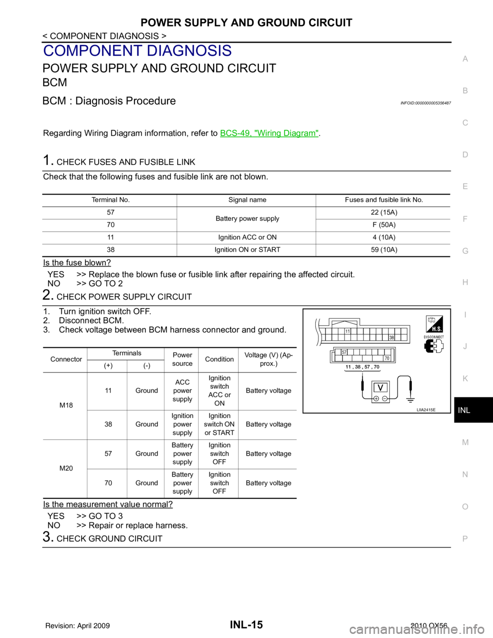
2. CHECK POWER SUPPLY CIRCUIT
1. Turn ignition switch OFF.
2. Disconnect BCM.
3. Check voltage between BCM harness connector and ground.
Is the measurement value normal?
YES >> GO TO 3
NO >> Repair or replace harness.
3. CHECK GROUND CIRCUIT
Terminal No. Signal nameFuses and fusible link No.
57 Battery power supply 22 (15A)
70 F (50A)
11 Ignition ACC or ON 4 (10A)
38 Ignition ON or START 59 (10A)
ConnectorTe r m i n a l s
Power
source Condition Voltage (V) (Ap-
prox.)
(+) (-)
M18 11 Ground
ACC
power
supply Ignition
switch
ACC or ON Battery voltage
38 Ground Ignition
power
supply Ignition
switch ON
or START Battery voltage
M20 57 Ground
Battery
power
supply Ignition
switch OFF Battery voltage
70 Ground Battery
power
supply Ignition
switch OFF Battery voltage
LIIA2415E
Revision: April 20092010 QX56
Page 2778 of 4210
MWI-16
< FUNCTION DIAGNOSIS >
METER SYSTEM
VOLTAGE GAUGE : Component Description
INFOID:0000000005146053
ODO/TRIP METER
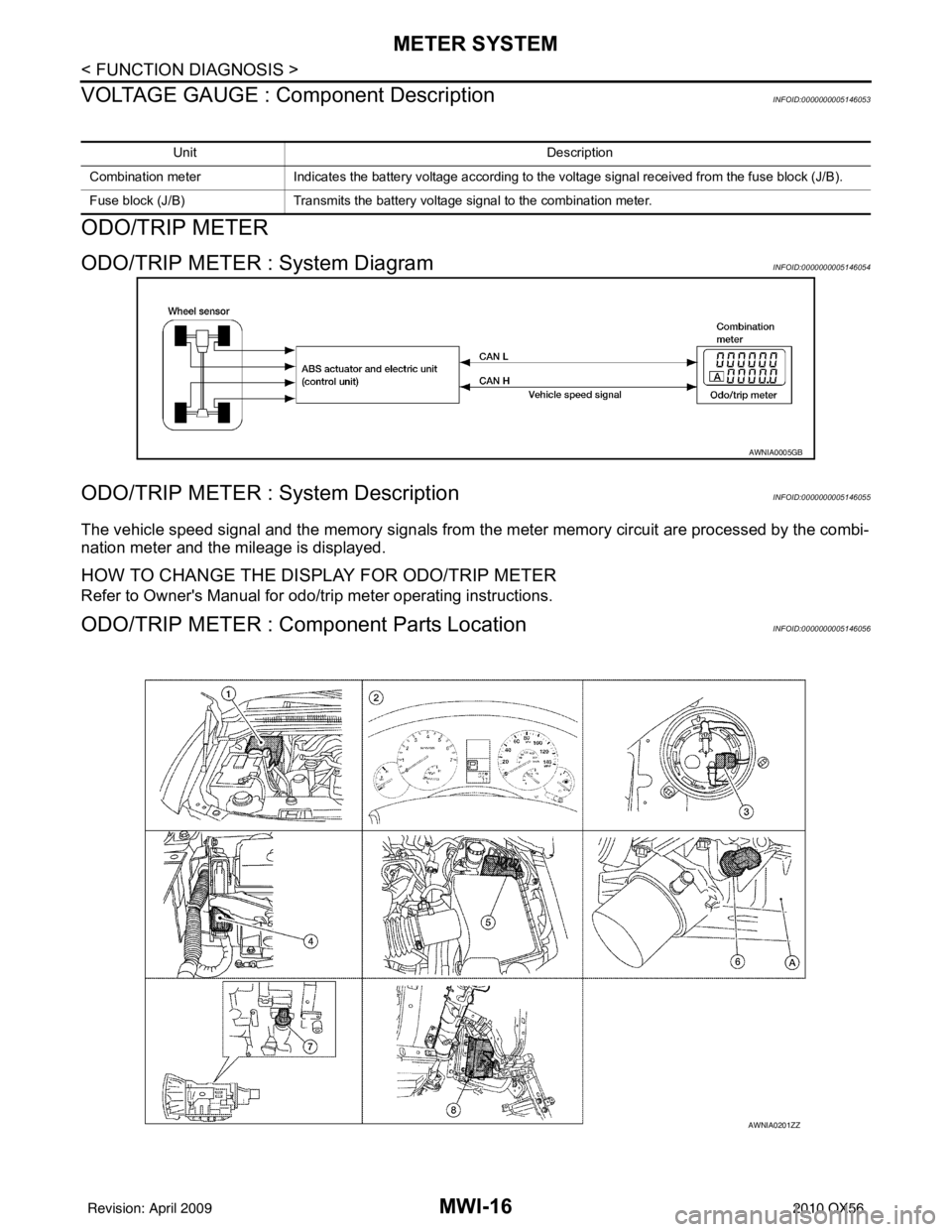
ODO/TRIP METER : System DiagramINFOID:0000000005146054
ODO/TRIP METER : System DescriptionINFOID:0000000005146055
The vehicle speed signal and the memory signals from the meter memory circuit are processed by the combi-
nation meter and the mileage is displayed.
HOW TO CHANGE THE DISPLAY FOR ODO/TRIP METER
Refer to Owner's Manual for odo/tr ip meter operating instructions.
ODO/TRIP METER : Component Parts LocationINFOID:0000000005146056
Unit Description
Combination meter Indicates the battery voltage according to the voltage signal received from the fuse block (J/B).
Fuse block (J/B) Transmits the battery voltage signal to the combination meter.
AWNIA0005GB
AWNIA0201ZZ
Revision: April 20092010 QX56