2010 INFINITI QX56 ecm
[x] Cancel search: ecmPage 2000 of 4210

EXL-24
< FUNCTION DIAGNOSIS >
DIAGNOSIS SYSTEM (IPDM E/R)
CONSULT - III Func tion (IPDM E/R)
INFOID:0000000005369887
APPLICATION ITEM
CONSULT-III performs the following functi ons via CAN communication with IPDM E/R.
SELF DIAGNOSTIC
Refer to PCS-32, "DTCIndex".
DATA MONITOR
Monitor item
Any of the following components do not operate
• Front wipers
•Tail lamps
• License plate lamps
• Parking lamps
•Front fog lamps
• Headlamps (Hi, Lo) Perform auto active test.
Does the applicable system
operate?YES BCM signal input system
NO • Lamp or front wiper motor
malfunction
• Lamp or front wiper motor ground circuit
• Harness or connector be-
tween IPDM E/R and appli-
cable system
• IPDM E/R (integrated relay
malfunction)
A/C compressor does not operate Perform auto active test.
Does the A/C compressor op-
erate?YES
• BCM signal input circuit
• CAN communication signal
between BCM and ECM
• CAN communication signal between ECM and IPDM E/
R
NO • Magnetic clutch malfunction
• Harness or connector be-
tween IPDM E/R and mag-
netic clutch
• IPDM E/R (integrated relay malfunction)
Cooling fan does not operate Perform auto active test.
Does the cooling fan operate?YES
• ECM signal input circuit
• CAN communication signal
between ECM and IPDM E/
R
NO • Cooling fan motor malfunc-
tion
• Harness or connector be- tween IPDM E/R and cool-
ing fan
• IPDM E/R (integrated relay malfunction)
Symptom
Inspection contentsPossible cause
Diagnosis mode Description
Self Diagnostic Result Displays the diagnosis results judged by IPDM E/R.
Data Monitor Displays the real-time input/output data from IPDM E/R input/output data.
Active Test IPDM E/R can provide a drive signal to electronic components to check their operations.
CAN Diag Support Monitor The results of transmit/receive diagnosis of CAN communication can be read.
Monitor Item
[Unit] MAIN SIG-
NALS Description
MOTOR FAN REQ
[1/2/3/4] ×
Displays the status of the cooling fan speed request signal received from ECM via
CAN communication.
A/C COMP REQ
[OFF/ON] ×Displays the status of the A/C request signal received from AV control unit via
CAN communication.
Revision: April 20092010 QX56
Page 2001 of 4210
![INFINITI QX56 2010 Factory Service Manual DIAGNOSIS SYSTEM (IPDM E/R)EXL-25
< FUNCTION DIAGNOSIS >
C
DE
F
G H
I
J
K
M A
B
EXL
N
O P
ACTIVE TEST
Te s t i t e m
TAIL&CLR REQ
[OFF/ON] ×Displays the status of the position light request signal r INFINITI QX56 2010 Factory Service Manual DIAGNOSIS SYSTEM (IPDM E/R)EXL-25
< FUNCTION DIAGNOSIS >
C
DE
F
G H
I
J
K
M A
B
EXL
N
O P
ACTIVE TEST
Te s t i t e m
TAIL&CLR REQ
[OFF/ON] ×Displays the status of the position light request signal r](/manual-img/42/57032/w960_57032-2000.png)
DIAGNOSIS SYSTEM (IPDM E/R)EXL-25
< FUNCTION DIAGNOSIS >
C
DE
F
G H
I
J
K
M A
B
EXL
N
O P
ACTIVE TEST
Te s t i t e m
TAIL&CLR REQ
[OFF/ON] ×Displays the status of the position light request signal received from BCM via CAN
communication.
HL LO REQ
[OFF/ON] ×
Displays the status of the low beam request signal received from BCM via CAN
communication.
HL HI REQ
[OFF/ON] ×Displays the status of the high beam request signal received from BCM via CAN
communication.
FR FOG REQ
[OFF/ON] ×Displays the status of the front fog lamp request signal received from BCM via
CAN communication.
FR WIP REQ
[STOP/1LOW/LOW/HI] ×
Displays the status of the front wiper request signal received from BCM via CAN
communication.
WIP AUTO STOP
[STOP P/ACT P] ×
Displays the status of the front wiper auto stop signal judged by IPDM E/R.
WIP PROT
[OFF/Block] ×
Displays the status of the front wiper fail-safe operation judged by IPDM E/R.
ST RLY REQ
[OFF/ON] Displays the status of the starter request signal received from ECM via CAN com-
munication.
IGN RLY
[OFF/ON] ×
Displays the status of the ignition relay judged by IPDM E/R.
RR DEF REQ
[OFF/ON] ×Displays the status of the rear defogger request signal received from AV control
unit via CAN communication.
OIL P SW
[OPEN/CLOSE] Displays the status of the oil pressure switch judged by IPDM E/R.
DTRL REQ
[OFF] Displays the status of the daytime light request signal received from BCM via CAN
communication.
HOOD SW
[OPEN/CLOSE] Displays the status of the hood switch judged by IPDM E/R.
THFT HRN REQ
[OFF/ON] Displays the status of the theft warning horn request signal received from BCM
via CAN communication.
HORN CHIRP
[OFF/ON] Displays the status of the horn reminder signal received from BCM via CAN com-
munication.
Monitor Item
[Unit] MAIN SIG-
NALS Description
Test item
Operation Description
REAR DEFOGGER OFF
OFF
ON Operates rear window defogger relay.
FRONT WIPER OFF
OFF
LO Operates the front wiper relay.
HI Operates the front wiper relay and front wiper high relay.
MOTOR FAN 1O
FF
2O FF
3 Operates the cooling fan relay.
4 Operates the cooling fan relay.
Revision: April 20092010 QX56
Page 2096 of 4210

EXL-120
< ECU DIAGNOSIS >
BCM (BODY CONTROL MODULE)
DTC Inspection Priority Chart
INFOID:0000000005369895
If some DTCs are displayed at the same time, perform inspections one by one based on the following priority
chart.
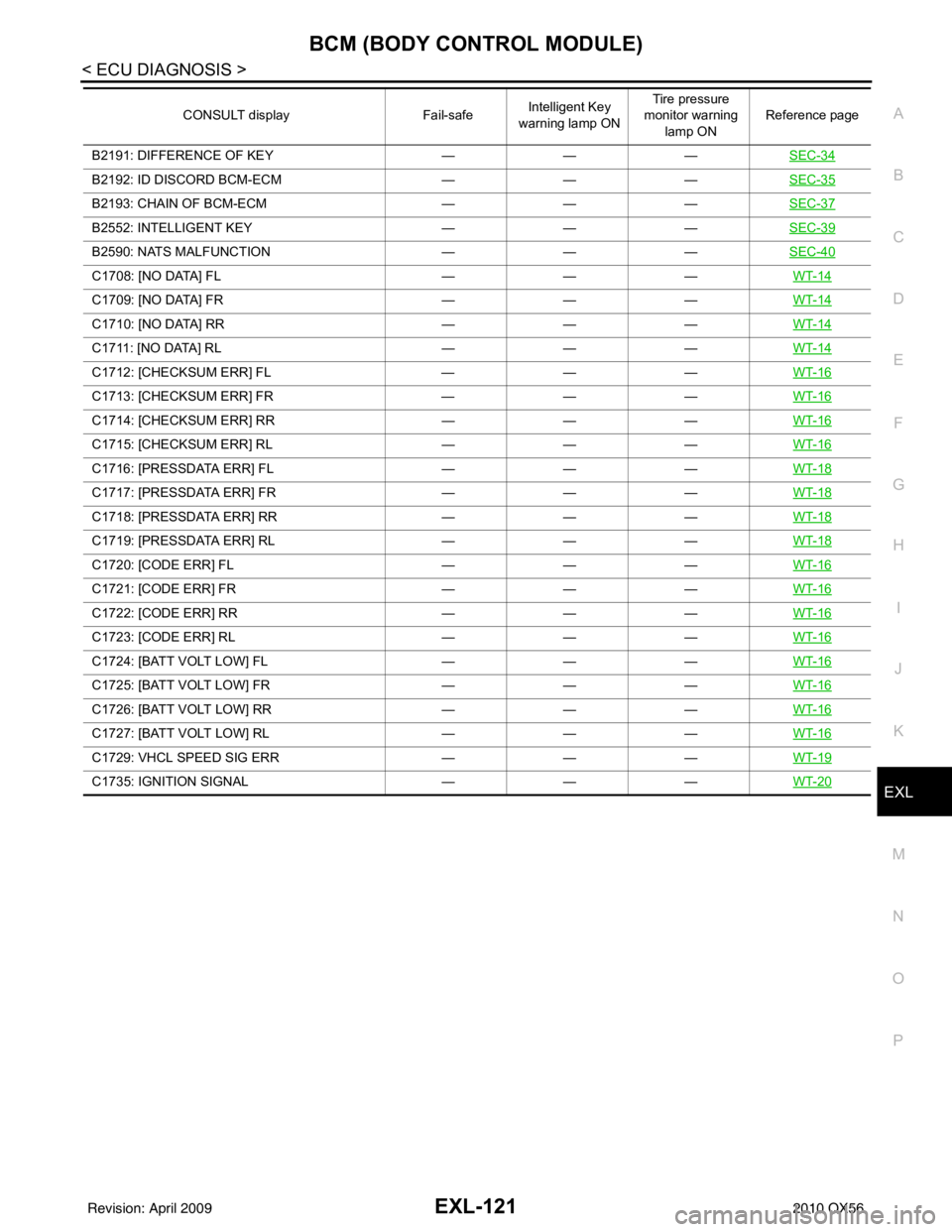
DTC IndexINFOID:0000000005369896
NOTE: Details of time display
• CRNT: Displays when there is a malfunction now or after returning to the normal condition until turning igni- tion switch OFF → ON again.
• 1 - 39: Displayed if any previous malfunction is present when current condition is normal. It increases like 1
→ 2 → 3...38 → 39 after returning to the normal condition whenever ignition switch OFF → ON. The counter
remains at 39 even if the number of cycles exceeds it. It is counted from 1 again when turning ignition switch
OFF → ON after returning to the normal condition if the malfunction is detected again.
Display contents of CONS ULTFail-safe Cancellation
U1000: CAN COMM CIRCUIT I nhibit engine crankingWhen the BCM re-establishes communication with the other mod-
ules.
Priority
DTC
1 • U1000: CAN COMM CIRCUIT
2 • B2190: NATS ANTENNA AMP
• B2191: DIFFERENCE OF KEY
• B2192: ID DISCORD BCM-ECM
• B2193: CHAIN OF BCM-ECM
• B2013: STRG COMM 1
• B2552: INTELLIGENT KEY
• B2590: NATS MALFUNCTION
3 • C1729: VHCL SPEED SIG ERR
• C1735: IGNITION SIGNAL
4 • C1708: [NO DATA] FL
• C1709: [NO DATA] FR
• C1710: [NO DATA] RR
• C1711: [NO DATA] RL
• C1712: [CHECKSUM ERR] FL
• C1713: [CHECKSUM ERR] FR
• C1714: [CHECKSUM ERR] RR
• C1715: [CHECKSUM ERR] RL
• C1716: [PRESSDATA ERR] FL
• C1717: [PRESSDATA ERR] FR
• C1718: [PRESSDATA ERR] RR
• C1719: [PRESSDATA ERR] RL
• C1720: [CODE ERR] FL
• C1721: [CODE ERR] FR
• C1722: [CODE ERR] RR
• C1723: [CODE ERR] RL
• C1724: [BATT VOLT LOW] FL
• C1725: [BATT VOLT LOW] FR
• C1726: [BATT VOLT LOW] RR
• C1727: [BATT VOLT LOW] RL
CONSULT display
Fail-safeIntelligent Key
warning lamp ON Tire pressure
monitor warning lamp ON Reference page
No DTC is detected.
further testing
may be required. ————
U1000: CAN COMM CIRCUIT ———BCS-32
B2190: NATS ANTENNA AMP ———SEC-31
Revision: April 20092010 QX56
Page 2097 of 4210

BCM (BODY CONTROL MODULE)EXL-121
< ECU DIAGNOSIS >
C
DE
F
G H
I
J
K
M A
B
EXL
N
O P
B2191: DIFFERENCE OF KEY ———SEC-34
B2192: ID DISCORD BCM-ECM ———SEC-35
B2193: CHAIN OF BCM-ECM ———SEC-37
B2552: INTELLIGENT KEY ———SEC-39
B2590: NATS MALFUNCTION ———SEC-40
C1708: [NO DATA] FL ———WT-14
C1709: [NO DATA] FR ———WT-14
C1710: [NO DATA] RR ———WT-14
C1711: [NO DATA] RL ———WT-14
C1712: [CHECKSUM ERR] FL ———WT-16
C1713: [CHECKSUM ERR] FR ———WT-16
C1714: [CHECKSUM ERR] RR ———WT-16
C1715: [CHECKSUM ERR] RL ———WT-16
C1716: [PRESSDATA ERR] FL ———WT-18
C1717: [PRESSDATA ERR] FR ———WT-18
C1718: [PRESSDATA ERR] RR ———WT-18
C1719: [PRESSDATA ERR] RL ———WT-18
C1720: [CODE ERR] FL ———WT-16
C1721: [CODE ERR] FR ———WT-16
C1722: [CODE ERR] RR ———WT-16
C1723: [CODE ERR] RL ———WT-16
C1724: [BATT VOLT LOW] FL ———WT-16
C1725: [BATT VOLT LOW] FR ———WT-16
C1726: [BATT VOLT LOW] RR ———WT-16
C1727: [BATT VOLT LOW] RL ———WT-16
C1729: VHCL SPEED SIG ERR ———WT-19
C1735: IGNITION SIGNAL ———WT-20
CONSULT display Fail-safeIntelligent Key
warning lamp ON Tire pressure
monitor warning
lamp ON Reference page
Revision: April 20092010 QX56
Page 2102 of 4210

EXL-126
< ECU DIAGNOSIS >
IPDM E/R (INTELLIGENT POWER DISTRIBUTION MODULE ENGINE ROOM)
Te r m i n a lWire
color Signal name Signal
input/
output Measuring condition
Reference value(Approx.)
Igni-
tion
switch Operation or condition
1 B/Y Battery power supply Input OFF —Battery voltage
2 R Battery power supply Input OFF —Battery voltage
3 BR ECM relay Output —Ignition switch ON or START
Battery voltage
Ignition switch OFF or ACC 0V
4 W/L ECM relay Output —Ignition switch ON or START
Battery voltage
Ignition switch OFF or ACC 0V
6L Throttle control motor
relay Output —Ignition switch ON or START
Battery voltage
Ignition switch OFF or ACC 0V
7 W/B ECM relay control Input — Ignition switch ON or START
0V
Ignition switch OFF or ACC Battery voltage
8 R/B Fuse 54 Output —Ignition switch ON or START
Battery voltage
Ignition switch OFF or ACC 0V
10 G Fuse 45
(Canada only) Output ONDaytime light system active
0V
Daytime light system inactive Battery voltage
11 Y/B A/C compressor Output ON or
START A/C switch ON or defrost A/C
switch
Battery voltage
A/C switch OFF or defrost A/C
switch 0V
12 L/W Ignition switch sup-
plied power Input —OFF or ACC
0V
ON or START Battery voltage
13 B/Y Fuel pump relay Output — Ignition switch ON or START
Battery voltage
Ignition switch OFF or ACC 0V
14 Y/R Fuse 49 Output —Ignition switch ON or START
Battery voltage
Ignition switch OFF or ACC 0V
15 LG/B Fuse 50 Output —Ignition switch ON or START
Battery voltage
Ignition switch OFF or ACC 0V
16 G Fuse 51 Output —Ignition switch ON or START
Battery voltage
Ignition switch OFF or ACC 0V
17 W Fuse 55 Output —Ignition switch ON or START
Battery voltage
Ignition switch OFF or ACC 0V
19 W/R Starter motor Output START—Battery voltage
21 BR Ignition switch sup-
plied power
Input —OFF or ACC
0V
START Battery voltage
22 G Battery power supply Output OFF —Battery voltage
23 GR/W Door mirror defogger
output signal Output —When rear defogger switch is
ON
Battery voltage
When raker defogger switch is
OFF 0V
24 L Cooling fan relay Output — Conditions correct for cooling
fan operation
Battery voltage
Conditions not correct for
cooling fan operation 0V
Revision: April 20092010 QX56
Page 2109 of 4210

IPDM E/R (INTELLIGENT POWER DISTRIBUTION MODULE ENGINE ROOM)
EXL-133
< ECU DIAGNOSIS >
C
D E
F
G H
I
J
K
M A
B
EXL
N
O P
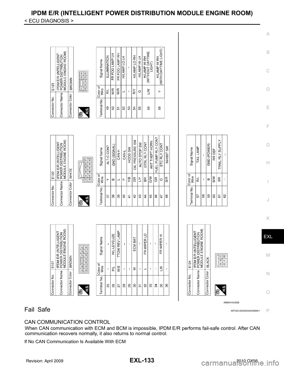
Fail SafeINFOID:0000000005369901
CAN COMMUNICATION CONTROL
When CAN communication with ECM and BCM is impossible, IPDM E/R performs fail-s afe control. After CAN
communication recovers normally, it also returns to normal control.
If No CAN Communication Is Available With ECM
ABMIA1043GB
Revision: April 20092010 QX56
Page 2239 of 4210

GI-16
< HOW TO USE THIS MANUAL >
TERMINOLOGY
TERMINOLOGY
SAE J1930 Terminology ListINFOID:0000000005149582
All emission related terms used in this publication in accordance with SAE J1930 are listed. Accordingly, new
terms, new acronyms/abbreviations and old terms are listed in the following chart.
NEW TERMNEW ACRONYM /
ABBREVIATION OLD TERM
Air cleaner ACL Air cleaner
Barometric pressure BARO ***
Barometric pressure sensor-BCDD BAROS-BCDD BCDD
Camshaft position CMP ***
Camshaft position sensor CMPSCrank angle sensor
Canister *** Canister
Carburetor CARBCarburetor
Charge air cooler CACIntercooler
Closed loop CLClosed loop
Closed throttle position switch CTP switchIdle switch
Clutch pedal position switch CPP switch Clutch switch
Continuous fuel injection system CFI system***
Continuous trap oxidizer system CTOX system ***
Crankshaft position CKP***
Crankshaft position sensor CKPS***
Data link connector DLC***
Data link connector for CONSULT-III DLC for CONSULT-IIIDiagnostic connector for CONSULT-III
Diagnostic test mode DTMDiagnostic mode
Diagnostic test mode selector DTM selectorDiagnostic mode selector
Diagnostic test mode I DTM I Mode I
Diagnostic test mode II DTM IIMode II
Diagnostic trouble code DTCMalfunction code
Direct fuel injection system DFI system ***
Distributor ignition system DI system Ignition timing control
Early fuel evaporation-mixture heater EFE-mixture heater Mixture heater
Early fuel evaporation system EFE system Mixture heater control
Electrically erasable programmable read
only memory EEPROM
***
Electronic ignition system EI systemIgnition timing control
Engine control EC ***
Engine control module ECM ECCS control unit
Engine coolant temperature ECT Engine temperature
Engine coolant temperature sensor ECTS Engine temperature sensor
Engine modification EM ***
Engine speed RPM Engine speed
Erasable programmable read only memory EPROM ***
Evaporative emission canister EVAP canister Canister
Evaporative emission system EVAP system Canister control solenoid valve
Exhaust gas recirculation valve EGR valve EGR valve
Revision: April 20092010 QX56
Page 2249 of 4210

GI-26
< PRECAUTION >
PRECAUTIONS
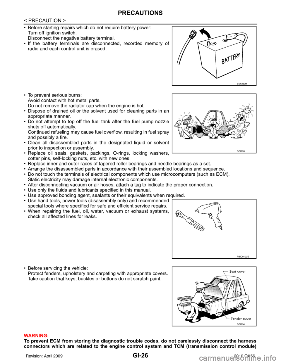
• Before starting repairs which do not require battery power:Turn off ignition switch.
Disconnect the negative battery terminal.
• If the battery terminals are disconnected, recorded memory of radio and each control unit is erased.
• To prevent serious burns: Avoid contact with hot metal parts.
Do not remove the radiator cap when the engine is hot.
• Dispose of drained oil or the solvent used for cleaning parts in an appropriate manner.
• Do not attempt to top off the fuel tank after the fuel pump nozzle
shuts off automatically.
Continued refueling may cause fuel overflow, resulting in fuel spray
and possibly a fire.
• Clean all disassembled parts in the designated liquid or solvent prior to inspection or assembly.
• Replace oil seals, gaskets, packings, O-rings, locking washers,
cotter pins, self-locking nuts, etc. with new ones.
• Replace inner and outer races of tapered roller bearings and needle bearings as a set.
• Arrange the disassembled parts in accordance with their assembled locations and sequence.
• Do not touch the terminals of electrical com ponents which use microcomputers (such as ECM).
Static electricity may damage internal electronic components.
• After disconnecting vacuum or air hoses, atta ch a tag to indicate the proper connection.
• Use only the fluids and lubricants specified in this manual.
• Use approved bonding agent, sealants or their equivalents when required.
• Use hand tools, power tools (disassembly only) and recommended special tools where specified for safe and efficient service repairs.
• When repairing the fuel, oil, water, vacuum or exhaust systems, check all affected lines for leaks.
• Before servicing the vehicle: Protect fenders, upholstery and carpeting with appropriate covers.
Take caution that keys, buckles or buttons do not scratch paint.
WARNING:
To prevent ECM from storing the diagnostic tro uble codes, do not carelessly disconnect the harness
connectors which are related to the engine control system and TCM (transmission control module)
SEF289H
SGI233
PBIC0190E
SGI234
Revision: April 20092010 QX56