Page 1991 of 4210
TURN SIGNAL AND HAZARD WARNING LAMPSEXL-15
< FUNCTION DIAGNOSIS >
C
DE
F
G H
I
J
K
M A
B
EXL
N
O P
TURN SIGNAL AND HA ZARD WARNING LAMPS
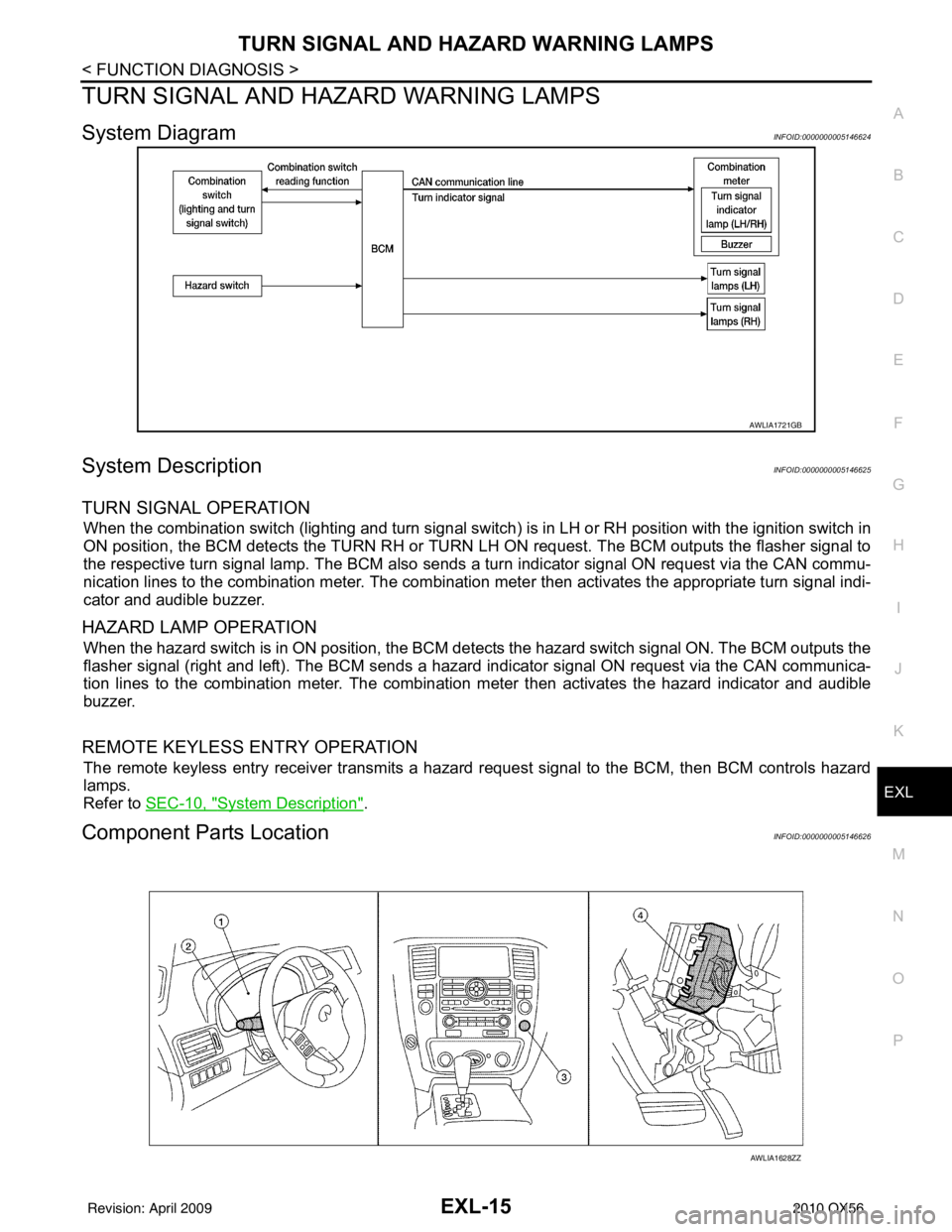
System DiagramINFOID:0000000005146624
System DescriptionINFOID:0000000005146625
TURN SIGNAL OPERATION
When the combination switch (lighting and turn signal switch) is in LH or RH position with the ignition switch in
ON position, the BCM detects the TURN RH or TURN LH ON request. The BCM outputs the flasher signal to
the respective turn signal lamp. The BCM also sends a turn indicator signal ON request via the CAN commu-
nication lines to the combination meter. The combination meter then activates the appropriate turn signal indi-
cator and audible buzzer.
HAZARD LAMP OPERATION
When the hazard switch is in ON position, the BCM detects the hazard switch signal ON. The BCM outputs the
flasher signal (right and left). The BCM sends a hazar d indicator signal ON request via the CAN communica-
tion lines to the combination meter. The combinati on meter then activates the hazard indicator and audible
buzzer.
REMOTE KEYLESS ENTRY OPERATION
The remote keyless entry receiver transmits a hazard request signal to the BCM, then BCM controls hazard
lamps.
Refer to SEC-10, "
System Description".
Component Parts LocationINFOID:0000000005146626
AWLIA1721GB
AWLIA1628ZZ
Revision: April 20092010 QX56
Page 2083 of 4210

BCM (BODY CONTROL MODULE)EXL-107
< ECU DIAGNOSIS >
C
DE
F
G H
I
J
K
M A
B
EXL
N
O P
LIGHT SW 1ST Lighting switch OFF OFF
Lighting switch 1st
ON
HEAD LAMP SW1 Headlamp switch OFF
OFF
Headlamp switch 1st ON
HEAD LAMP SW2 Headlamp switch OFF
OFF
Headlamp switch 1st ON
HI BEAM SW High beam switch OFF
OFF
High beam switch HI ON
IGN ON SW Ignition switch OFF or ACC
OFF
Ignition switch ON ON
IGN SW CAN Ignition switch OFF or ACC
OFF
Ignition switch ON ON
INT VOLUME Wiper intermittent dial is in a dial position 1 - 7 1 - 7
I-KEY LOCK LOCK button of Intelligent Key is not pressed
OFF
LOCK button of Intelligent Key is pressed ON
I-KEY UNLOCK UNLOCK button of Intelligent Key is not pressed
OFF
UNLOCK button of Intelligent Key is pressed ON
KEY CYL LK-SW Door key cylinder LOCK position
ON
Door key cylinder other than LOCK position OF
KEY CYL UN-SW Door key cylinder UNLOCK position
ON
Door key cylinder other than UNLOCK position ON
KEY ON SW Mechanical key is removed from key cylinder
OFF
Mechanical key is inserted to key cylinder ON
OIL PRESS SW • Ignition switch OFF or ACC
• Engine running
OFF
Ignition switch ON ON
OPTICAL SENSOR Bright outside of the vehicle
Close to 5V
Dark outside of the vehicle Close to 0V
PASSING SW Other than lighting switch PASS
OFF
Lighting switch PASS ON
PUSH SW Return to ignition switch to LOCK position
OFF
Press ignition switch ON
REAR DEF SW Rear window defogger switch OFF
OFF
Rear window defogger switch ON ON
RR WASHER SW Rear washer switch OFF
OFF
Rear washer switch ON ON
RR WIPER INT Rear wiper switch OFF
OFF
Rear wiper switch INT ON
RR WIPER ON Rear wiper switch OFF
OFF
Rear wiper switch ON ON
RR WIPER STOP Rear wiper stop position
OFF
Other than rear wiper stop position ON
RR WIPER STP2 Rear wiper stop position
OFF
Other than rear wiper stop position ON
Monitor Item
Condition Value/Status
Revision: April 20092010 QX56
Page 2086 of 4210
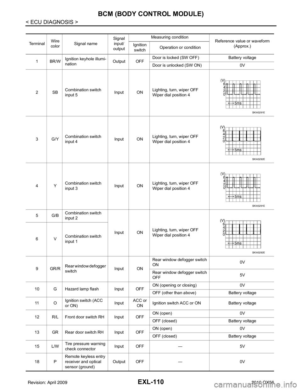
EXL-110
< ECU DIAGNOSIS >
BCM (BODY CONTROL MODULE)
Te r m i n a lWire
color Signal name Signal
input/
output Measuring condition
Reference value or waveform
(Approx.)
Ignition
switch Operation or condition
1BR/W Ignition keyhole illumi-
nation Output OFFDoor is locked (SW OFF)
Battery voltage
Door is unlocked (SW ON) 0V
2SB Combination switch
input 5 Input ON
Lighting, turn, wiper OFF
Wiper dial position 4
3G/Y Combination switch
input 4 Input ONLighting, turn, wiper OFF
Wiper dial position 4
4Y Combination switch
input 3 Input ON
Lighting, turn, wiper OFF
Wiper dial position 4
5G/B Combination switch
input 2
Input ONLighting, turn, wiper OFF
Wiper dial position 4
6V Combination switch
input 1
9GR/R Rear window defogger
switch
Input ONRear window defogger switch
ON
0V
Rear window defogger switch
OFF 5V
10 G Hazard lamp flash Input OFF ON (opening or closing)
0V
OFF (other than above) Battery voltage
11 O Ignition switch (ACC
or ON)
InputACC or
ON Ignition switch ACC or ON
Battery voltage
12 R/L Front door switch RH Input OFF ON (open)
0V
OFF (closed) Battery voltage
13 GR Rear door switch RH Input OFF ON (open)
0V
OFF (closed) Battery voltage
15 L/W Tire pressure warning
check connector
Input OFF
—5V
18 P Remote keyless entry
receiver and optical
sensor (ground)
Output OFF
—0V
SKIA5291E
SKIA5292E
SKIA5291E
SKIA5292E
Revision: April 20092010 QX56
Page 2087 of 4210
BCM (BODY CONTROL MODULE)EXL-111
< ECU DIAGNOSIS >
C
DE
F
G H
I
J
K
M A
B
EXL
N
O P
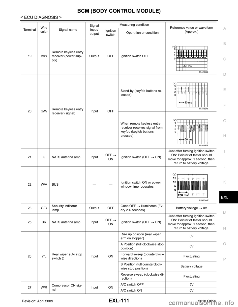
19 V/W Remote keyless entry
receiver (power sup-
ply) Output OFF Ignition switch OFF
20 G/W Remote keyless entry
receiver (signal) Input OFFStand-by (keyfob buttons re-
leased)
When remote keyless entry
receiver receives signal from
keyfob (keyfob buttons
pressed)
21 G NATS antenna amp. Input OFF
→
ON Ignition switch (OFF → ON) Just after turning ignition switch
ON: Pointer of tester should
move for approx. 1 second, then return to battery voltage.
22 W/V BUS — —Ignition switch ON or power
window timer operates
23 G/O Security indicator
lamp Output OFF
Goes OFF
→ illuminates (Ev-
ery 2.4 seconds) Battery voltage
→ 0V
25 BR NATS antenna amp. Input OFF
→
ON Ignition switch (OFF → ON) Just after turning ignition switch
ON: Pointer of tester should
move for approx. 1 second, then return to battery voltage.
26 Y/L Rear wiper auto stop
switch 2 Input ONRise up position (rear wiper
arm on stopper)
0V
A Position (full clockwise stop
position) 0V
Forward sweep (counterclock-
wise direction) Fluctuating
B Position (full counterclock-
wise stop position) Battery voltage
Reverse sweep (clockwise di-
rection) Fluctuating
27 W/R Compressor ON sig-
nal Input ONA/C switch OFF
5V
A/C switch ON 0V
Te r m i n a l
Wire
color Signal name Signal
input/
output Measuring condition
Reference value or waveform
(Approx.)
Ignition
switch Operation or condition
LIIA1893E
LIIA1894E
LIIA1895E
PIIA2344E
Revision: April 20092010 QX56
Page 2088 of 4210
EXL-112
< ECU DIAGNOSIS >
BCM (BODY CONTROL MODULE)
28 L/R Front blower monitor Input ONFront blower motor OFF
Battery voltage
Front blower motor ON 0V
29 W/B Hazard switch Input OFFON
0V
OFF 5V
30 Y/BR Glass hatch switch Input OFF Glass hatch switch released
0V
Glass hatch switch pressed Battery
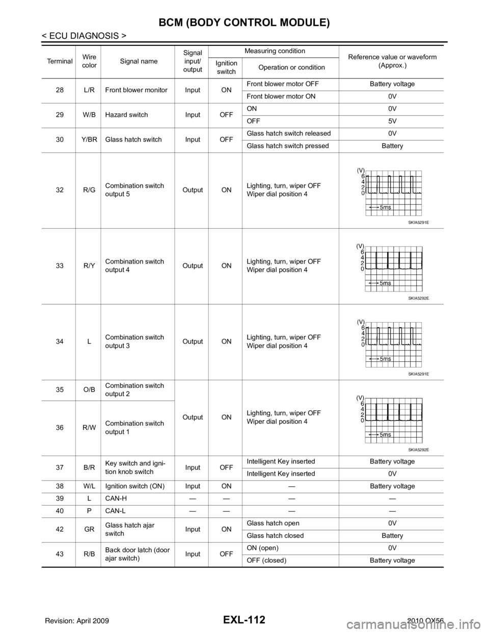
32 R/G Combination switch
output 5
Output ONLighting, turn, wiper OFF
Wiper dial position 4
33 R/Y Combination switch
output 4 Output ONLighting, turn, wiper OFF
Wiper dial position 4
34 L Combination switch
output 3 Output ON
Lighting, turn, wiper OFF
Wiper dial position 4
35 O/B Combination switch
output 2
Output ONLighting, turn, wiper OFF
Wiper dial position 4
36 R/W Combination switch
output 1
37 B/R Key switch and igni-
tion knob switch Input OFFIntelligent Key inserted
Battery voltage
Intelligent Key inserted 0V
38 W/L Ignition switch (ON) Input ON —Battery voltage
39 L CAN-H — —— —
40 P CAN-L — —— —
42 GR Glass hatch ajar
switch Input ONGlass hatch open
0V
Glass hatch closed Battery
43 R/B Back door latch (door
ajar switch) Input OFFON (open)
0V
OFF (closed) Battery voltage
Te r m i n a l
Wire
color Signal name Signal
input/
output Measuring condition
Reference value or waveform
(Approx.)
Ignition
switch Operation or condition
SKIA5291E
SKIA5292E
SKIA5291E
SKIA5292E
Revision: April 20092010 QX56
Page 2096 of 4210

EXL-120
< ECU DIAGNOSIS >
BCM (BODY CONTROL MODULE)
DTC Inspection Priority Chart
INFOID:0000000005369895
If some DTCs are displayed at the same time, perform inspections one by one based on the following priority
chart.
DTC IndexINFOID:0000000005369896
NOTE: Details of time display
• CRNT: Displays when there is a malfunction now or after returning to the normal condition until turning igni- tion switch OFF → ON again.
• 1 - 39: Displayed if any previous malfunction is present when current condition is normal. It increases like 1
→ 2 → 3...38 → 39 after returning to the normal condition whenever ignition switch OFF → ON. The counter
remains at 39 even if the number of cycles exceeds it. It is counted from 1 again when turning ignition switch
OFF → ON after returning to the normal condition if the malfunction is detected again.
Display contents of CONS ULTFail-safe Cancellation
U1000: CAN COMM CIRCUIT I nhibit engine crankingWhen the BCM re-establishes communication with the other mod-
ules.
Priority
DTC
1 • U1000: CAN COMM CIRCUIT
2 • B2190: NATS ANTENNA AMP
• B2191: DIFFERENCE OF KEY
• B2192: ID DISCORD BCM-ECM
• B2193: CHAIN OF BCM-ECM
• B2013: STRG COMM 1
• B2552: INTELLIGENT KEY
• B2590: NATS MALFUNCTION
3 • C1729: VHCL SPEED SIG ERR
• C1735: IGNITION SIGNAL
4 • C1708: [NO DATA] FL
• C1709: [NO DATA] FR
• C1710: [NO DATA] RR
• C1711: [NO DATA] RL
• C1712: [CHECKSUM ERR] FL
• C1713: [CHECKSUM ERR] FR
• C1714: [CHECKSUM ERR] RR
• C1715: [CHECKSUM ERR] RL
• C1716: [PRESSDATA ERR] FL
• C1717: [PRESSDATA ERR] FR
• C1718: [PRESSDATA ERR] RR
• C1719: [PRESSDATA ERR] RL
• C1720: [CODE ERR] FL
• C1721: [CODE ERR] FR
• C1722: [CODE ERR] RR
• C1723: [CODE ERR] RL
• C1724: [BATT VOLT LOW] FL
• C1725: [BATT VOLT LOW] FR
• C1726: [BATT VOLT LOW] RR
• C1727: [BATT VOLT LOW] RL
CONSULT display
Fail-safeIntelligent Key
warning lamp ON Tire pressure
monitor warning lamp ON Reference page
No DTC is detected.
further testing
may be required. ————
U1000: CAN COMM CIRCUIT ———BCS-32
B2190: NATS ANTENNA AMP ———SEC-31
Revision: April 20092010 QX56
Page 2097 of 4210
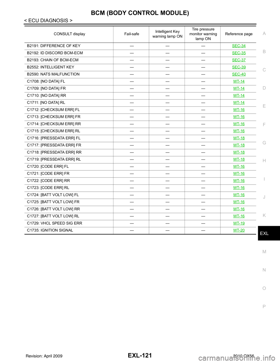
BCM (BODY CONTROL MODULE)EXL-121
< ECU DIAGNOSIS >
C
DE
F
G H
I
J
K
M A
B
EXL
N
O P
B2191: DIFFERENCE OF KEY ———SEC-34
B2192: ID DISCORD BCM-ECM ———SEC-35
B2193: CHAIN OF BCM-ECM ———SEC-37
B2552: INTELLIGENT KEY ———SEC-39
B2590: NATS MALFUNCTION ———SEC-40
C1708: [NO DATA] FL ———WT-14
C1709: [NO DATA] FR ———WT-14
C1710: [NO DATA] RR ———WT-14
C1711: [NO DATA] RL ———WT-14
C1712: [CHECKSUM ERR] FL ———WT-16
C1713: [CHECKSUM ERR] FR ———WT-16
C1714: [CHECKSUM ERR] RR ———WT-16
C1715: [CHECKSUM ERR] RL ———WT-16
C1716: [PRESSDATA ERR] FL ———WT-18
C1717: [PRESSDATA ERR] FR ———WT-18
C1718: [PRESSDATA ERR] RR ———WT-18
C1719: [PRESSDATA ERR] RL ———WT-18
C1720: [CODE ERR] FL ———WT-16
C1721: [CODE ERR] FR ———WT-16
C1722: [CODE ERR] RR ———WT-16
C1723: [CODE ERR] RL ———WT-16
C1724: [BATT VOLT LOW] FL ———WT-16
C1725: [BATT VOLT LOW] FR ———WT-16
C1726: [BATT VOLT LOW] RR ———WT-16
C1727: [BATT VOLT LOW] RL ———WT-16
C1729: VHCL SPEED SIG ERR ———WT-19
C1735: IGNITION SIGNAL ———WT-20
CONSULT display Fail-safeIntelligent Key
warning lamp ON Tire pressure
monitor warning
lamp ON Reference page
Revision: April 20092010 QX56
Page 2099 of 4210
IPDM E/R (INTELLIGENT POWER DISTRIBUTION MODULE ENGINE ROOM)
EXL-123
< ECU DIAGNOSIS >
C
D E
F
G H
I
J
K
M A
B
EXL
N
O P
THFT HRN REQ Not operated
OFF
• Panic alarm is activated
• Horn is activated with VEHICLE SECURITY (THEFT WARNING) SYS-
TEM ON
HORN CHIRP Not operated
OFF
Door locking with Intelligent Key (horn chirp mode) ON
Monitor Item
ConditionValue/Status
Revision: April 20092010 QX56