2010 INFINITI QX56 light
[x] Cancel search: lightPage 3732 of 4210
DIAGNOSIS SYSTEM (TCM)TM-37
< FUNCTION DIAGNOSIS >
CEF
G H
I
J
K L
M A
B
TM
N
O P
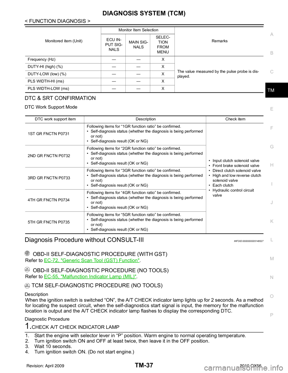
DTC & SRT CONFIRMATION
DTC Work Support Mode
Diagnosis Procedure without CONSULT-IIIINFOID:0000000005148527
OBD-II SELF-DIAGNOSTIC PROCEDURE (WITH GST)
Refer to EC-72, "Generic Scan Tool (GST) Function".
OBD-II SELF-DIAGNOSTIC PROCEDURE (NO TOOLS)
Refer to EC-55, "Malfunction Indicator Lamp (MIL)".
TCM SELF-DIAGNOSTIC PROCEDURE (NO TOOLS)
Description
When the ignition switch is switched “ON”, the A/T CHECK indicator lamp lights up for 2 seconds. As a method
for locating the suspect circuit, when the self-diagnosti cs start signal is input, the memory for the malfunction
location is output and the A/T CHECK indicator lamp flashes to display the corresponding DTC.
Diagnostic Procedure
1.CHECK A/T CHECK INDICATOR LAMP
1. Start the engine with selector lever in “P” pos ition. Warm engine to normal operating temperature.
2. Turn ignition switch ON and OFF at least twice, then leave it in the OFF position.
3. Wait 10 seconds.
4. Turn ignition switch ON. (Do not start engine.)
Frequency (Hz) —— X
The value measured by the pulse probe is dis-
played.
DUTY-HI (high) (%)
—— X
DUTY-LOW (low) (%) —— X
PLS WIDTH-HI (ms) —— X
PLS WIDTH-LOW (ms) —— X
Monitored item (Unit)
Monitor Item Selection
Remarks
ECU IN-
PUT SIG- NALS MAIN SIG-
NALS SELEC-
TION
FROM
MENU
DTC work support item DescriptionCheck item
1ST GR FNCTN P0731 Following items for “1GR function ratio” be confirmed.
• Self-diagnosis status (whether the diagnosis is being performed
or not)
• Self-diagnosis result (OK or NG)
• Input clutch solenoid valve
• Front brake solenoid valve
• Direct clutch solenoid valve
• High and low reverse clutch solenoid valve
• Each clutch
• Hydraulic co ntrol circuit
valve
2ND GR FNCTN P0732
Following items for “2GR function ratio” be confirmed.
• Self-diagnosis status (whether the diagnosis is being performed
or not)
• Self-diagnosis result (OK or NG)
3RD GR FNCTN P0733 Following items for “3GR function ratio” be confirmed.
• Self-diagnosis status (whether the diagnosis is being performed
or not)
• Self-diagnosis result (OK or NG)
4TH GR FNCTN P0734 Following items for “4GR function ratio” be confirmed.
• Self-diagnosis status (whether the diagnosis is being performed
or not)
• Self-diagnosis result (OK or NG)
5TH GR FNCTN P0735 Following items for “5GR function ratio” be confirmed.
• Self-diagnosis status (whether the diagnosis is being performed
or not)
• Self-diagnosis result (OK or NG)
Revision: April 20092010 QX56
Page 3733 of 4210
TM-38
< FUNCTION DIAGNOSIS >
DIAGNOSIS SYSTEM (TCM)
Does A/T CHECK indicator lamp come on for about 2 seconds?
YES >> GO TO 2.
NO >> GO TO TM-121, "
Symptom Table".
2.JUDGMENT PROCEDURE STEP 1
1. Turn ignition switch OFF.
2. Keep pressing shift lock release button.
3. Move selector lever from “P” to “D” position.
4. Release accelerator pedal. (Set the closed throttle position signal “ON”.)
5. Depress brake pedal. (Stop lamp switch signal “ON”.)
6. Turn ignition switch ON. (Do not start engine.)
7. Wait 3 seconds.
8. Move the selector lever from “D” to “3” position.
9. Release brake pedal. (Stop lamp switch signal “OFF”.)
10. Move the selector lever from “3” to “2” position.
11. Depress brake pedal. (Stop lamp switch signal “ON”.)
12. Depress accelerator pedal fully and release it.
>> GO TO 3.
3.CHECK SELF-DIAGNOSIS CODE
Check A/T CHECK indicator lamp.
Refer to "Judgment Self-diagnosis Code".
If the system does not go into self-diagnostics. Refer to TM-45, "
Diagnosis Procedure", TM-96, "Diagnosis
Procedure", TM-97, "Diagnosis Procedure".
>> DIAGNOSIS END
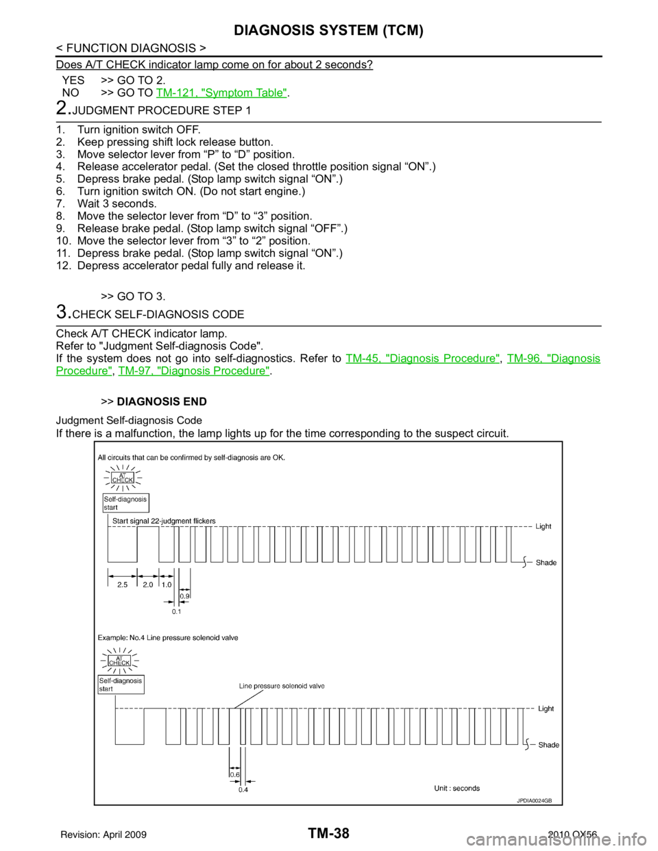
Judgment Self-diagnosis Code
If there is a malfunction, the lamp lights up for the time corresponding to the suspect circuit.
JPDIA0024GB
Revision: April 20092010 QX56
Page 3801 of 4210
TM-106
< ECU DIAGNOSIS >
TCM
ECU DIAGNOSIS
TCM
Reference ValueINFOID:0000000005148688
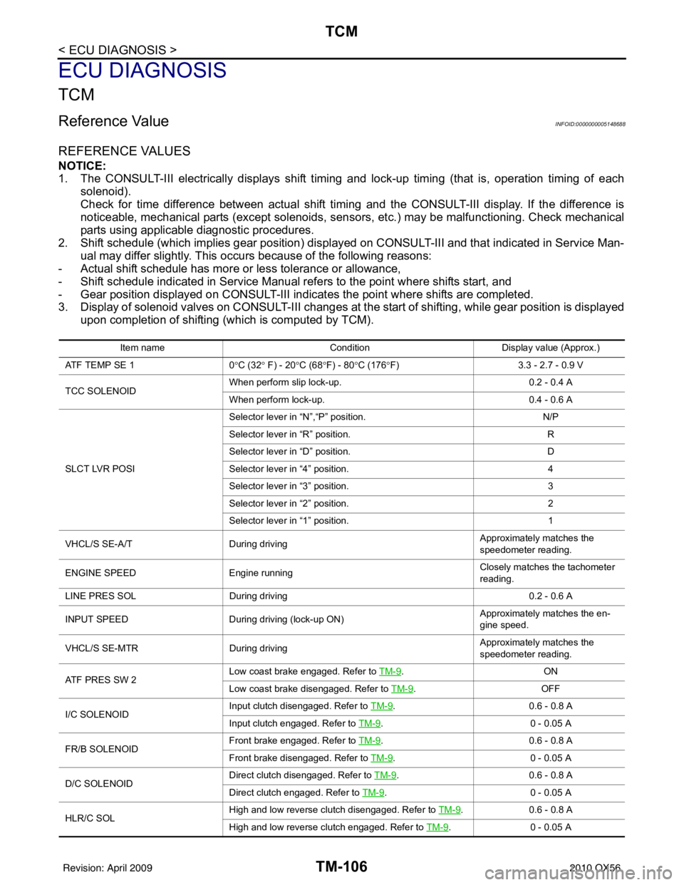
REFERENCE VALUES
NOTICE:
1. The CONSULT-III electrically displays shift timing and lock-up timing (that is, operation timing of eachsolenoid).
Check for time difference between actual shift timi ng and the CONSULT-III display. If the difference is
noticeable, mechanical parts (except solenoids, sens ors, etc.) may be malfunctioning. Check mechanical
parts using applicable diagnostic procedures.
2. Shift schedule (which implies gear position) display ed on CONSULT-III and that indicated in Service Man-
ual may differ slightly. This occurs because of the following reasons:
- Actual shift schedule has more or less tolerance or allowance,
- Shift schedule indicated in Service Manual refers to the point where shifts start, and
- Gear position displayed on CONSULT-III indicates the point where shifts are completed.
3. Display of solenoid valves on CONSULT-III changes at t he start of shifting, while gear position is displayed
upon completion of shifting (which is computed by TCM).
Item name Condition Display value (Approx.)
AT F T E M P S E 1 0°C (32 ° F) - 20 °C (68 °F) - 80 °C (176 °F) 3.3 - 2.7 - 0.9 V
TCC SOLENOID When perform slip lock-up.
0.2 - 0.4 A
When perform lock-up. 0.4 - 0.6 A
SLCT LVR POSI Selector lever in “N”,“P” position.
N/P
Selector lever in “R” position. R
Selector lever in “D” position. D
Selector lever in “4” position. 4
Selector lever in “3” position. 3
Selector lever in “2” position. 2
Selector lever in “1” position. 1
VHCL/S SE-A/T During driving Approximately matches the
speedometer reading.
ENGINE SPEED Engine running Closely matches the tachometer
reading.
LINE PRES SOL During driving 0.2 - 0.6 A
INPUT SPEED During driving (lock-up ON) Approximately matches the en-
gine speed.
VHCL/S SE-MTR During driving Approximately matches the
speedometer reading.
ATF PRES SW 2 Low coast brake engaged. Refer to
TM-9
.ON
Low coast brake disengaged. Refer to TM-9
.OFF
I/C SOLENOID Input clutch disengaged. Refer to
TM-9
.0.6 - 0 .8 A
Input clutch engaged. Refer to TM-9
.0 - 0 .0 5 A
FR/B SOLENOID Front brake engaged. Refer to
TM-9
.0 .6 - 0 .8 A
Front brake disengaged. Refer to TM-9
.0 - 0 .0 5 A
D/C SOLENOID Direct clutch disengaged. Refer to
TM-9
.0.6 - 0 .8 A
Direct clutch engaged. Refer to TM-9
.0 - 0 .0 5 A
HLR/C SOL High and low reverse clutch disengaged. Refer to
TM-9
.0.6 - 0 .8 A
High and low reverse clutch engaged. Refer to TM-9
.0 - 0 .0 5 A
Revision: April 20092010 QX56
Page 3838 of 4210
PRECAUTIONSTM-143
< PRECAUTION >
CEF
G H
I
J
K L
M A
B
TM
N
O P
PRECAUTION
PRECAUTIONS
Precaution for Supplemental Restraint System (SRS) "AIR BAG" and "SEAT BELT
PRE-TENSIONER"
INFOID:0000000005148716
The Supplemental Restraint System such as “AIR BAG” and “SEAT BELT PRE-TENSIONER”, used along
with a front seat belt, helps to reduce the risk or severi ty of injury to the driver and front passenger for certain
types of collision. This system includes seat belt switch inputs and dual stage front air bag modules. The SRS
system uses the seat belt switches to determine the front air bag deployment, and may only deploy one front
air bag, depending on the severity of a collision and w hether the front occupants are belted or unbelted.
Information necessary to service the system safely is included in the SR and SB section of this Service Man-
ual.
WARNING:
• To avoid rendering the SRS inoper ative, which could increase the risk of personal injury or death in
the event of a collision which would result in air bag inflation, all maintenance must be performed by
an authorized NISSAN/INFINITI dealer.
• Improper maintenance, including in correct removal and installation of the SRS, can lead to personal
injury caused by unintentional act ivation of the system. For removal of Spiral Cable and Air Bag
Module, see the SR section.
• Do not use electrical test equipm ent on any circuit related to the SRS unless instructed to in this
Service Manual. SRS wiring harnesses can be identi fied by yellow and/or orange harnesses or har-
ness connectors.
Precaution for On Board Diagnosis (OBD) System of A/T and EngineINFOID:0000000005148717
The ECM has an on board diagnostic system . It will light up the malfunction indicator lamp (MIL) to warn the
driver of a malfunction causing emission deterioration.
CAUTION:
• Be sure to turn the ignition switch “OFF” and disconnect the negative battery cable before any repair or inspection work. The open/short circuit of related switches, sen sors, solenoid valves, etc. Will
cause the MIL to light up.
• Be sure to connect and lock the connectors secure ly after work. A loose (unlocked) connector will
cause the MIL to light up due to an open circuit. (Be sure the connector is free from water, grease,
dirt, bent terminals, etc.)
• Be sure to route and secure the harnesses properly after work. Interference of the harness with a
bracket, etc. May cause the MIL to li ght up due to a short circuit.
• Be sure to connect rubber tubes properly afte r work. A misconnected or disconnected rubber tube
may cause the MIL to light up due to a malfunction of the EGR system or fuel injection system, etc.
• Be sure to erase the unnecessary malfunction informa tion (repairs completed) from the TCM and
ECM before returning the vehicle to the customer.
PrecautionINFOID:0000000005148718
NOTE:
If any malfunctions occur in th e RE5R05A model transmission, repl ace the entire transmission assem-
bly.
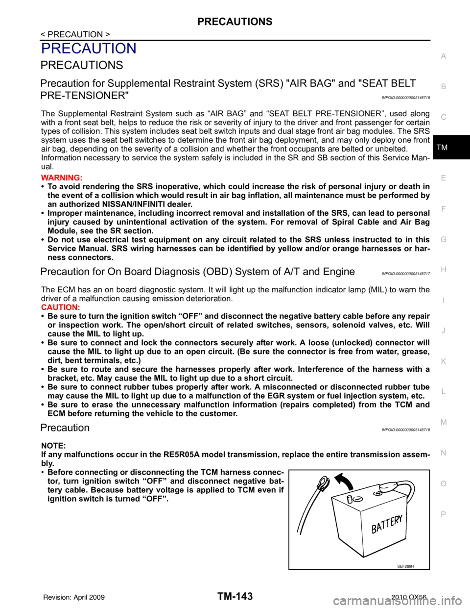
• Before connecting or disconn ecting the TCM harness connec-
tor, turn ignition switch “O FF” and disconnect negative bat-
tery cable. Because battery voltage is applied to TCM even if
ignition switch is turned “OFF”.
SEF289H
Revision: April 20092010 QX56
Page 3854 of 4210
ROAD TESTTM-159
< ON-VEHICLE MAINTENANCE >
CEF
G H
I
J
K L
M A
B
TM
N
O P
ROAD TEST
DescriptionINFOID:0000000005148728
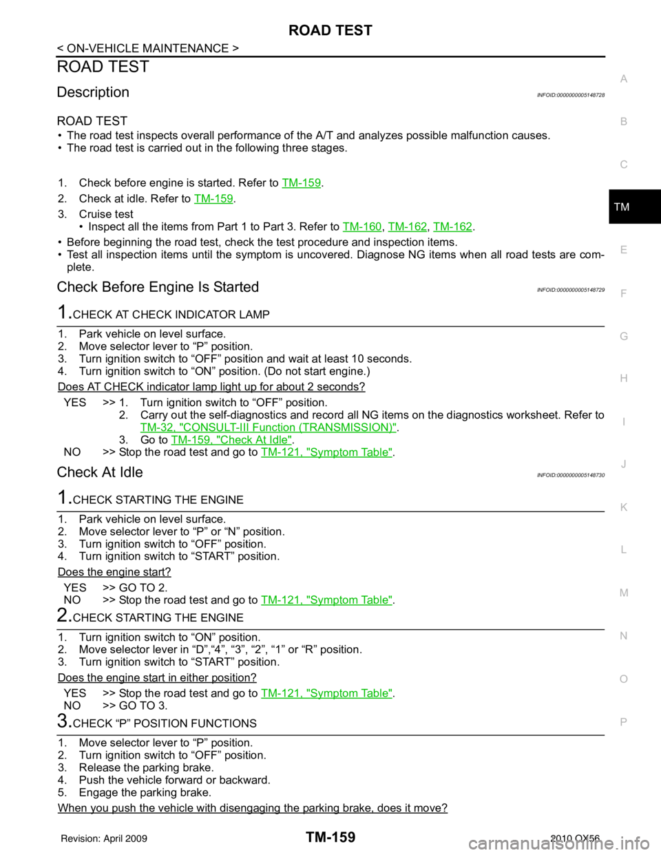
ROAD TEST
• The road test inspects overall performance of the A/T and analyzes possible malfunction causes.
• The road test is carried out in the following three stages.
1. Check before engine is started. Refer to TM-159
.
2. Check at idle. Refer to TM-159
.
3. Cruise test • Inspect all the items from Part 1 to Part 3. Refer to TM-160
, TM-162, TM-162.
• Before beginning the road test, check the test procedure and inspection items.
• Test all inspection items until the symptom is uncov ered. Diagnose NG items when all road tests are com-
plete.
Check Before Engine Is StartedINFOID:0000000005148729
1.CHECK AT CHECK INDICATOR LAMP
1. Park vehicle on level surface.
2. Move selector lever to “P” position.
3. Turn ignition switch to “OFF” position and wait at least 10 seconds.
4. Turn ignition switch to “ON” position. (Do not start engine.)
Does AT CHECK indicator lamp light up for about 2 seconds?
YES >> 1. Turn ignition switch to “OFF” position. 2. Carry out the self-diagnostics and record all NG items on the diagnostics worksheet. Refer toTM-32, "
CONSULT-III Function (TRANSMISSION)".
3. Go to TM-159, "
Check At Idle".
NO >> Stop the road test and go to TM-121, "
Symptom Table".
Check At IdleINFOID:0000000005148730
1.CHECK STARTING THE ENGINE
1. Park vehicle on level surface.
2. Move selector lever to “P” or “N” position.
3. Turn ignition switch to “OFF” position.
4. Turn ignition switch to “START” position.
Does the engine start?
YES >> GO TO 2.
NO >> Stop the road test and go to TM-121, "
Symptom Table".
2.CHECK STARTING THE ENGINE
1. Turn ignition switch to “ON” position.
2. Move selector lever in “D”,“4”, “3”, “2”, “1” or “R” position.
3. Turn ignition switch to “START” position.
Does the engine start in either position?
YES >> Stop the road test and go to TM-121, "Symptom Table".
NO >> GO TO 3.
3.CHECK “P” POSITION FUNCTIONS
1. Move selector lever to “P” position.
2. Turn ignition switch to “OFF” position.
3. Release the parking brake.
4. Push the vehicle forward or backward.
5. Engage the parking brake.
When you push the vehicle with disengaging the parking brake, does it move?
Revision: April 20092010 QX56
Page 3856 of 4210
ROAD TESTTM-161
< ON-VEHICLE MAINTENANCE >
CEF
G H
I
J
K L
M A
B
TM
N
O P
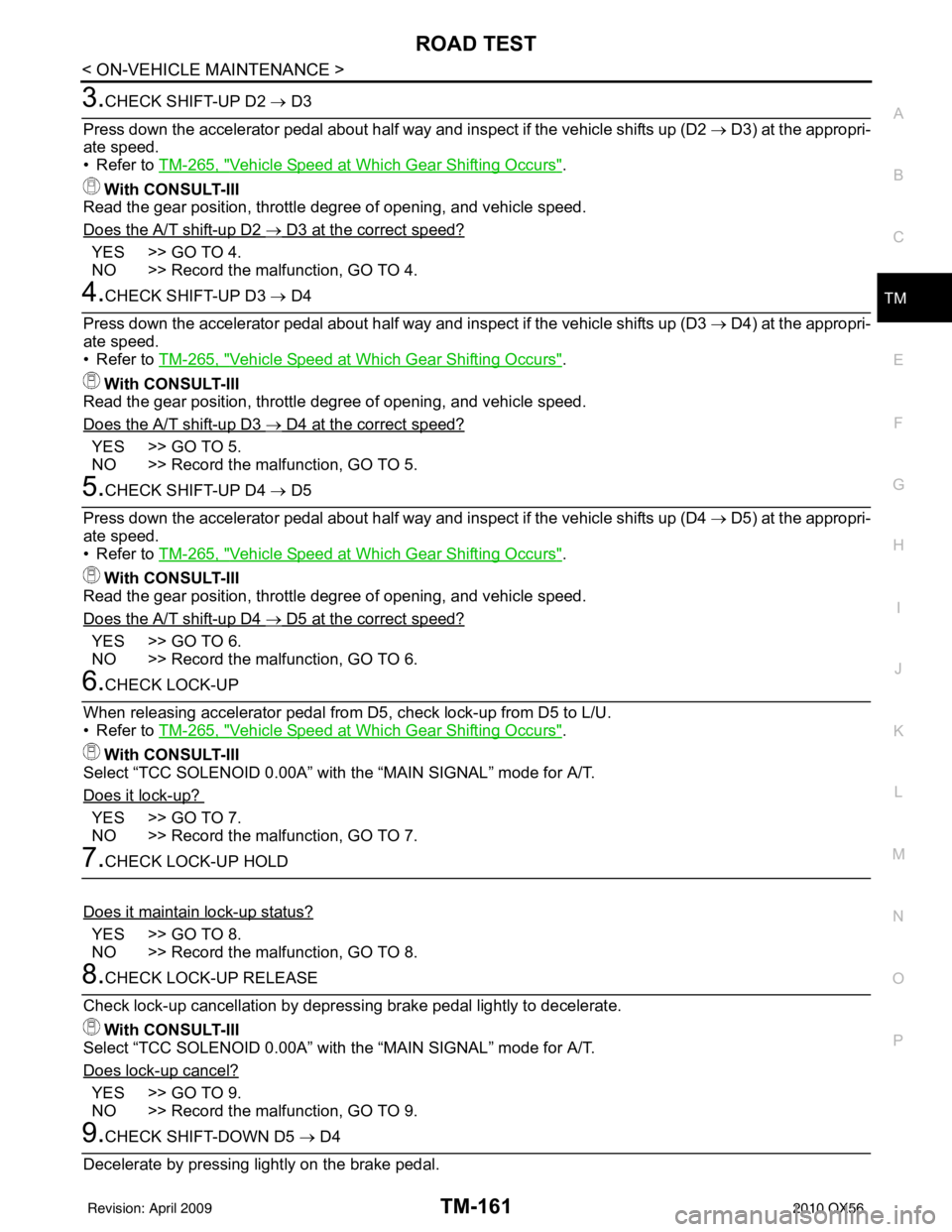
3.CHECK SHIFT-UP D2 → D3
Press down the accelerator pedal about half way and inspect if the vehicle shifts up (D2 → D3) at the appropri-
ate speed.
• Refer to TM-265, "
Vehicle Speed at Which Gear Shifting Occurs".
With CONSULT-III
Read the gear position, throttle degree of opening, and vehicle speed.
Does the A/T shift-up D2
→ D3 at the correct speed?
YES >> GO TO 4.
NO >> Record the malfunction, GO TO 4.
4.CHECK SHIFT-UP D3 → D4
Press down the accelerator pedal about half way and inspect if the vehicle shifts up (D3 → D4) at the appropri-
ate speed.
• Refer to TM-265, "
Vehicle Speed at Which Gear Shifting Occurs".
With CONSULT-III
Read the gear position, throttle degree of opening, and vehicle speed.
Does the A/T shift-up D3
→ D4 at the correct speed?
YES >> GO TO 5.
NO >> Record the malfunction, GO TO 5.
5.CHECK SHIFT-UP D4 → D5
Press down the accelerator pedal about half way and inspect if the vehicle shifts up (D4 → D5) at the appropri-
ate speed.
• Refer to TM-265, "
Vehicle Speed at Which Gear Shifting Occurs".
With CONSULT-III
Read the gear position, throttle degree of opening, and vehicle speed.
Does the A/T shift-up D4
→ D5 at the correct speed?
YES >> GO TO 6.
NO >> Record the malfunction, GO TO 6.
6.CHECK LOCK-UP
When releasing accelerator pedal from D5, check lock-up from D5 to L/U.
• Refer to TM-265, "
Vehicle Speed at Which Gear Shifting Occurs".
With CONSULT-III
Select “TCC SOLENOID 0.00A” with the “MAIN SIGNAL” mode for A/T.
Does it lock-up?
YES >> GO TO 7.
NO >> Record the malfunction, GO TO 7.
7.CHECK LOCK-UP HOLD
Does it maintain lock-up status?
YES >> GO TO 8.
NO >> Record the malfunction, GO TO 8.
8.CHECK LOCK-UP RELEASE
Check lock-up cancellation by depressing brake pedal lightly to decelerate. With CONSULT-III
Select “TCC SOLENOID 0.00A” with the “MAIN SIGNAL” mode for A/T.
Does lock-up cancel?
YES >> GO TO 9.
NO >> Record the malfunction, GO TO 9.
9.CHECK SHIFT-DOWN D5 → D4
Decelerate by pressing lightly on the brake pedal.
Revision: April 20092010 QX56
Page 3885 of 4210
TM-190
< REMOVAL AND INSTALLATION >
TRANSMISSION ASSEMBLY
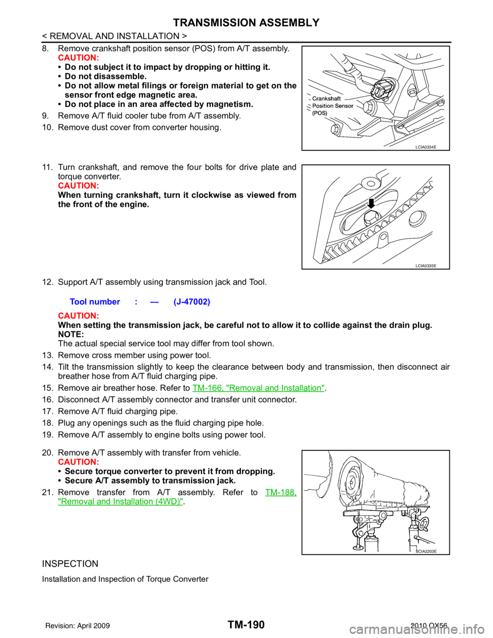
8. Remove crankshaft position sensor (POS) from A/T assembly.CAUTION:
• Do not subject it to impact by dropping or hitting it.
• Do not disassemble.
• Do not allow metal filings or fo reign material to get on the
sensor front edge magnetic area.
• Do not place in an area affected by magnetism.
9. Remove A/T fluid cooler tube from A/T assembly.
10. Remove dust cover from converter housing.
11. Turn crankshaft, and remove the four bolts for drive plate and torque converter.
CAUTION:
When turning crankshaft, turn it clockwise as viewed from
the front of the engine.
12. Support A/T assembly using transmission jack and Tool. CAUTION:
When setting the transmission jack, be careful not to allow it to collide against the drain plug.
NOTE:
The actual special service tool may differ from tool shown.
13. Remove cross member using power tool.
14. Tilt the transmission slightly to keep the cl earance between body and transmission, then disconnect air
breather hose from A/T fluid charging pipe.
15. Remove air breather hose. Refer to TM-166, "
Removal and Installation".
16. Disconnect A/T assembly connector and transfer unit connector.
17. Remove A/T fluid charging pipe.
18. Plug any openings such as the fluid charging pipe hole.
19. Remove A/T assembly to engine bolts using power tool.
20. Remove A/T assembly with transfer from vehicle. CAUTION:
• Secure torque converter to prevent it from dropping.
• Secure A/T assembly to transmission jack.
21. Remove transfer from A/T assembly. Refer to TM-188,
"Removal and Installation (4WD)".
INSPECTION
Installation and Inspection of Torque Converter
LCIA0334E
LCIA0335E
Tool number : — (J-47002)
SCIA2203E
Revision: April 20092010 QX56
Page 3940 of 4210
ASSEMBLYTM-245
< DISASSEMBLY AND ASSEMBLY >
CEF
G H
I
J
K L
M A
B
TM
N
O P
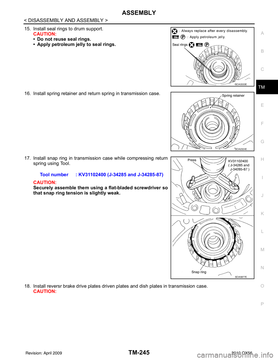
15. Install seal rings to drum support. CAUTION:
• Do not reuse seal rings.
• Apply petroleum jelly to seal rings.
16. Install spring retainer and return spring in transmission case.
17. Install snap ring in transmission case while compressing return spring using Tool.
CAUTION:
Securely assemble them using a flat-bladed screwdriver so
that snap ring tension is slightly weak.
18. Install reversr brake drive plates driven pl ates and dish plates in transmission case.
CAUTION:
SCIA3333E
SCIA2324E
Tool number : KV31102400 (J-34285 and J-34285-87)
SCIA5877E
Revision: April 20092010 QX56