Page 3729 of 4210

TM-34
< FUNCTION DIAGNOSIS >
DIAGNOSIS SYSTEM (TCM)
*1: Refer to EC-55, "Malfunction Indicator Lamp (MIL)".
*2:These malfunctions cannot be displayed MIL if another malfunction is assigned to MIL.
DATA MONITOR MODE
Display Items List
X: Standard, —: Not applicable
L C BRAKE SOLENOID • TCM detects an improper voltage drop when it tries to
operate the solenoid valve.
• Condition of ATF pressure switch 2 is different from
monitor value, and relation between gear position and
actual gear ratio is irregular. P1774 P1774*2
TM-93
NO DTC IS DETECTED
FURTHER TESTING
MAY BE REQUIRED• No NG item has been detected.
XX —
Items (CONSULT-III
screen terms) Malfunction is detected when... TCM self-di-
agnosis OBD (DTC)
Reference
“TRANSMIS-
SION” with
CONSULT-III MIL indicator
lamp*1, “EN-
GINE” with
CONSULT-III or
GST
Monitored item (Unit) Monitor Item Selection
Remarks
ECU IN-
PUT SIG-
NALS MAIN SIG-
NALS SELEC-
TION
FROM
MENU
VHCL/S SE-A/T (km/h) XXX Output speed sensor
VHCL/S SE-MTR (km/h) X— X —
ACCELE POSI (0.0/8) X— X Accelerator pedal position signal
THROTTLE POSI (0.0/8) XXXDegree of opening for accelerator recognized by
the TCM.
For fail-safe operation, the specific value used
for control is displayed.
CLSD THL POS (ON-OFF display) X— X
Signal input with CAN communications.
W/O THL POS (ON-OFF display) X— X
BRAKESW (ON-OFF display) X— X Stop lamp switch
GEAR —XXGear position recognized by the TCM updated
after gear-shifting.
ENGINE SPEED (rpm) XXX —
INPUT SPEED (rpm) XXX —
OUTPUT REV (rpm) XXX —
GEAR RATIO —XX —
TC SLIP SPEED (rpm) —XXDifference between engine speed and torque
converter input shaft speed.
F SUN GR REV (rpm) —— X —
F CARR GR REV (rpm) —— X —
ATF TEMP SE 1 (V) X— X —
ATF TEMP 1 (° C) —XX —
ATF TEMP 2 (° C) —XX —
BATTERY VOLT (V) X— X —
ATF PRES SW 1 (ON-OFF display) XXX —
ATF PRES SW 2 (ON-OFF display) XXX (for LC/B solenoid)
Revision: April 20092010 QX56
Page 3792 of 4210

BRAKE SIGNAL CIRCUITTM-97
< COMPONENT DIAGNOSIS >
CEF
G H
I
J
K L
M A
B
TM
N
O P
BRAKE SIGNAL CIRCUIT
CONSULT-III Reference Val ue in Data Monitor ModeINFOID:0000000005148681
Diagnosis ProcedureINFOID:0000000005148682
1.CHECK CAN COMMUNICATION LINE
Perform the self-diagnosis. Refer to TM-32, "
CONSULT-III Function (TRANSMISSION)".
Is a malfunction in the CAN communication indicated in the results?
YES >> Check CAN communication line. Refer to TM-40, "Diagnosis Procedure".
NO >> GO TO 2.
2.CHECK STOP LAMP SWITCH CIRCUIT
With CONSULT-III
1. Turn ignition switch “ON”. (Do not start engine.)
2. Select “ECU INPUT SIGNALS” in “DATA MONITO R” mode for “TRANSMISSION” with CONSULT-III.
3. Read out ON/OFF switching action of the “BRAKESW”.
OK or NG
OK >> INSPECTION END
NG >> GO TO 3.
3.CHECK STOP LAMP SWITCH
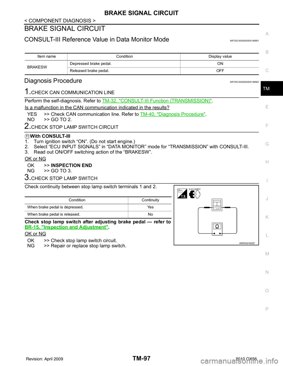
Check continuity between stop lamp switch terminals 1 and 2.
Check stop lamp switch after adjusting brake pedal — refer to
BR-15, "
Inspection and Adjustment".
OK or NG
OK >> Check stop lamp switch circuit.
NG >> Repair or replace stop lamp switch.
Item name Condition Display value
BRAKESW Depressed brake pedal.
ON
Released brake pedal. OFF
ConditionContinuity
When brake pedal is depressed. Yes
When brake pedal is released. No
AWDIA0165ZZ
Revision: April 20092010 QX56
Page 3802 of 4210

TCM
TM-107
< ECU DIAGNOSIS >
C EF
G H
I
J
K L
M A
B
TM
N
O P
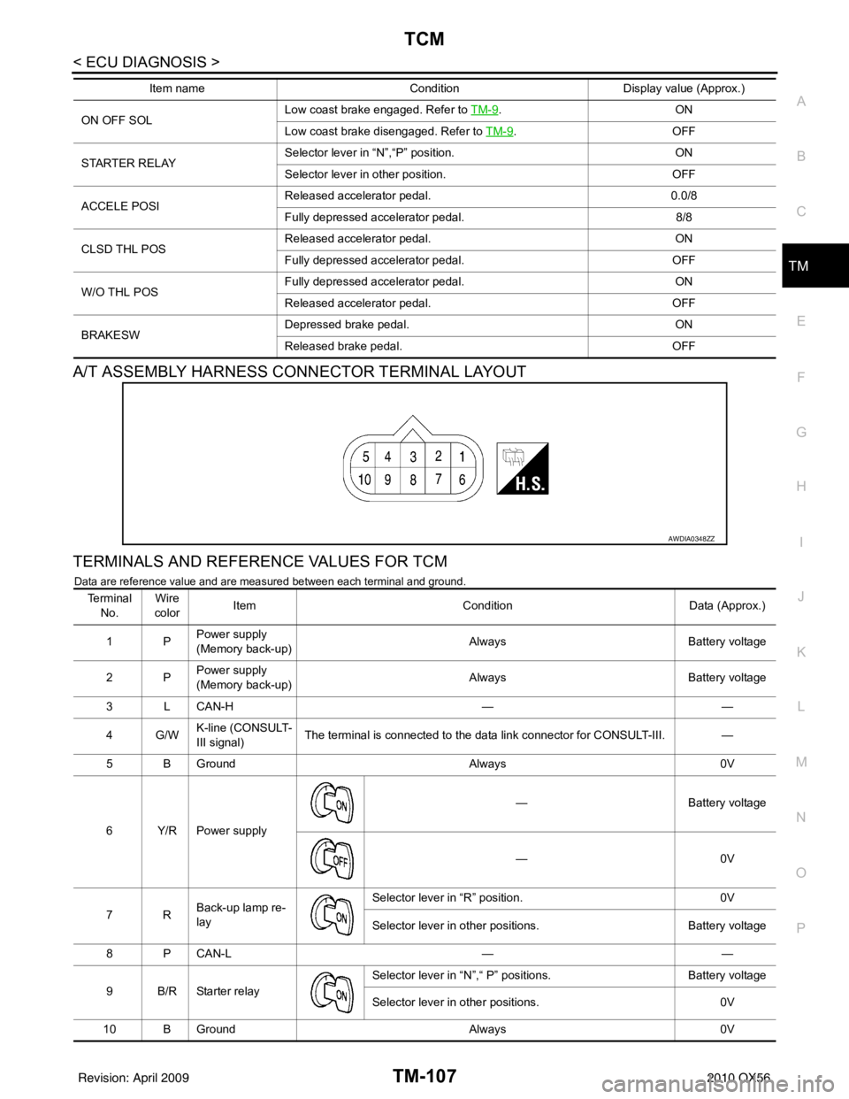
A/T ASSEMBLY HARNESS CONNECTOR TERMINAL LAYOUT
TERMINALS AND REFERENCE VALUES FOR TCM
Data are reference value and are measured between each terminal and ground.
ON OFF SOL Low coast brake engaged. Refer to
TM-9.ON
Low coast brake disengaged. Refer to TM-9
.OFF
STARTER RELAY Selector lever in
“N”,“P” position. ON
Selector lever in other position. OFF
ACCELE POSI Released accelerator pedal.
0.0/8
Fully depressed accelerator pedal. 8/8
CLSD THL POS Released accelerator pedal.
ON
Fully depressed accelerator pedal. OFF
W/O THL POS Fully depressed accelerator pedal.
ON
Released accelerator pedal. OFF
BRAKESW Depressed brake pedal.
ON
Released brake pedal. OFF
Item name
Condition Display value (Approx.)
AWDIA0348ZZ
Te r m i n a l
No. Wire
color Item
ConditionData (Approx.)
1P Power supply
(Memory back-up)
Always
Battery voltage
2P Power supply
(Memory back-up) Always
Battery voltage
3 L CAN-H ——
4G/W K-line (CONSULT-
III signal) The terminal is connected to the data link connector for CONSULT-III. —
5 B Ground Always0V
6Y/RPower supply —
Battery voltage
—0 V
7R Back-up lamp re-
lay Selector lever in “R” position.
0V
Selector lever in other positions. Battery voltage
8 P CAN-L ——
9 B/R Starter relay Selector lever in “N”,“ P”
positions. Battery voltage
Selector lever in other positions. 0V
10 B Ground Always0V
Revision: April 20092010 QX56