2010 INFINITI QX56 brakes
[x] Cancel search: brakesPage 1324 of 4210
![INFINITI QX56 2010 Factory Service Manual DLN-242
< SYMPTOM DIAGNOSIS >[REAR FINAL DRIVE: R230]
NOISE, VIBRATION AND HARSHNESS
(NVH) TROUBLESHOOTING
SYMPTOM DIAGNOSIS
NOISE, VIBRATION AND HARSHNESS (NVH) TROUBLESHOOTING
NVH Troubleshooting C INFINITI QX56 2010 Factory Service Manual DLN-242
< SYMPTOM DIAGNOSIS >[REAR FINAL DRIVE: R230]
NOISE, VIBRATION AND HARSHNESS
(NVH) TROUBLESHOOTING
SYMPTOM DIAGNOSIS
NOISE, VIBRATION AND HARSHNESS (NVH) TROUBLESHOOTING
NVH Troubleshooting C](/manual-img/42/57032/w960_57032-1323.png)
DLN-242
< SYMPTOM DIAGNOSIS >[REAR FINAL DRIVE: R230]
NOISE, VIBRATION AND HARSHNESS
(NVH) TROUBLESHOOTING
SYMPTOM DIAGNOSIS
NOISE, VIBRATION AND HARSHNESS (NVH) TROUBLESHOOTING
NVH Troubleshooting ChartINFOID:0000000005148928
Use the chart below to help you find the cause of the sy mptom. If necessary, repair or replace these parts.
×: ApplicableReference page
DLN-253, "
Disassembly and Assembly
"
DLN-253, "
Disassembly and Assembly
"
DLN-253, "
Disassembly and Assembly
"
DLN-270, "
Inspection and Adjustment
"
DLN-270, "
Inspection and Adjustment
"
MA-13, "
Fluids and Lubricants
"
DLN-194, "
NVH Troubleshooting Chart
"
RAX-5, "
NVH Troubleshooting Chart
"
RSU-5, "
NVH Troubleshooting Chart
"
WT-43, "
NVH Troubleshooting Chart
"
WT-43, "
NVH Troubleshooting Chart
"
RAX-5, "
NVH Troubleshooting Chart
"
BR-6, "
NVH Troubleshooting Chart
"
ST-12, "
NVH Troubleshooting Chart
"
Possible cause and SUSPECTED PARTS
Gear tooth rough
Gear contact improper
Tooth surfaces worn
Backlash incorrect
Companion flange excessive runout
Gear oil improper
PROPELLER SHAFT
REAR AXLE
REAR SUSPENSION
TIRES
ROAD WHEEL
DRIVE SHAFT
BRAKES
STEERING
Symptom
Noise××××××× ××××××
Revision: April 20092010 QX56
Page 2171 of 4210
NOISE, VIBRATION AND HARSHNESS (NVH) TROUBLESHOOTINGFAX-5
< SYMPTOM DIAGNOSIS >
CEF
G H
I
J
K L
M A
B
FA X
N
O P
SYMPTOM DIAGNOSIS
NOISE, VIBRATION AND HARSHN ESS (NVH) TROUBLESHOOTING
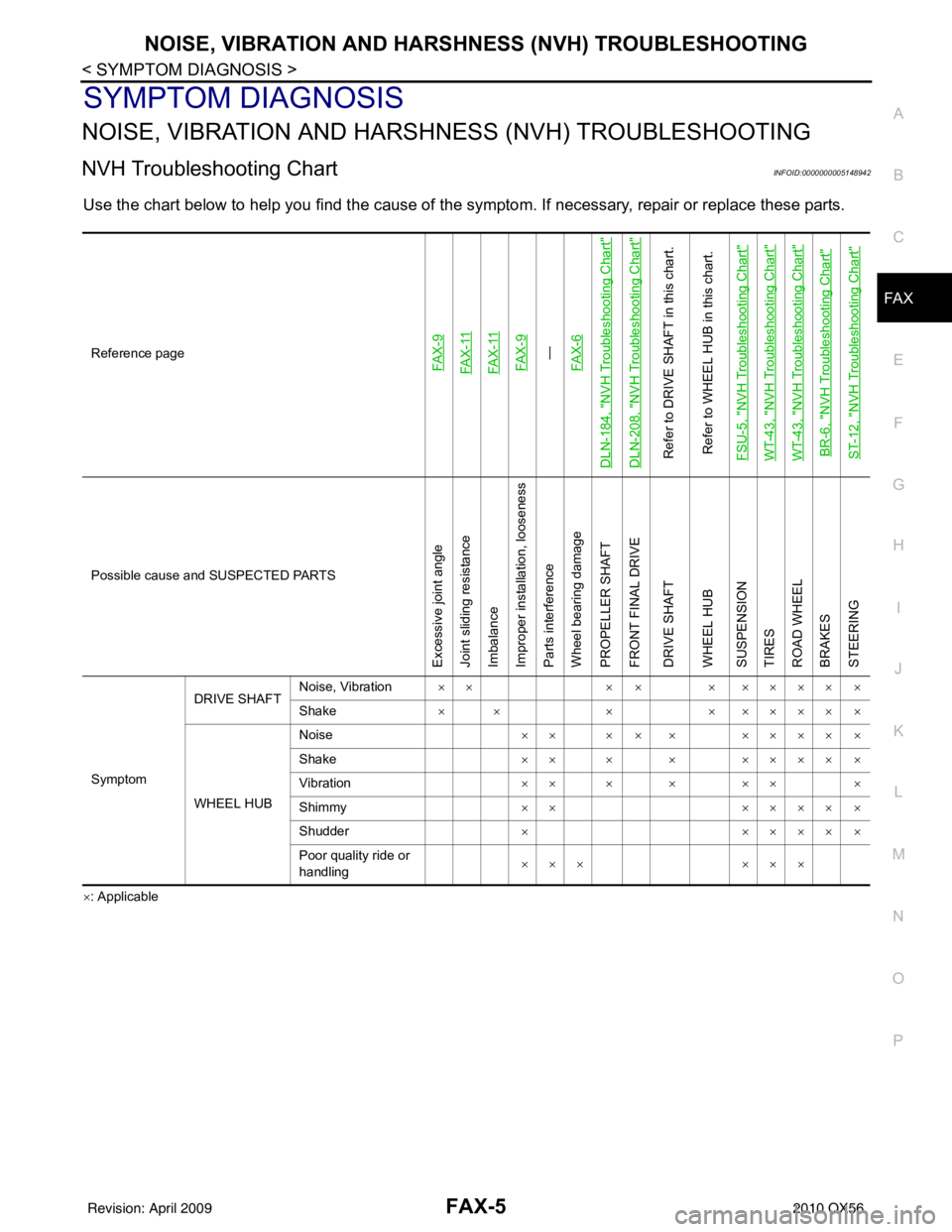
NVH Troubleshooting ChartINFOID:0000000005148942
Use the chart below to help you find t he cause of the symptom. If necessary, repair or replace these parts.
×: ApplicableReference page
FA X - 9FA X - 11FA X - 11FA X - 9—
FA X - 6
DLN-184, "
NVH Troubleshooting Chart
"
DLN-208, "
NVH Troubleshooting Chart
"
Refer to DRIVE SHAFT in this chart.
Refer to WHEEL HUB in this chart.
FSU-5, "
NVH Troubleshooting Chart
"
WT-43, "
NVH Troubleshooting Chart
"
WT-43, "
NVH Troubleshooting Chart
"
BR-6, "
NVH Troubleshooting Chart
"
ST-12, "
NVH Troubleshooting Chart
"
Possible cause and SUSPECTED PARTS
Excessive joint angle
Joint sliding resistance
Imbalance
Improper installation, looseness
Parts interference
Wheel bearing damage
PROPELLER SHAFT
FRONT FINAL DRIVE
DRIVE SHAFT
WHEEL HUB
SUSPENSION
TIRES
ROAD WHEEL
BRAKES
STEERING
Symptom DRIVE SHAFT
Noise, Vibration
×× × × × ×××× ×
Shake × × ×× ×××× ×
WHEEL HUB Noise
×× × × × ×××× ×
Shake ×× × × ×××× ×
Vibration ×× × × ×× ×
Shimmy ×××××× ×
Shudder ×× ××× ×
Poor quality ride or
handling ×××
×××
Revision: April 20092010 QX56
Page 2204 of 4210
NOISE, VIBRATION AND HARSHNESS (NVH) TROUBLESHOOTINGFSU-5
< SYMPTOM DIAGNOSIS >
C
DF
G H
I
J
K L
M A
B
FSU
N
O P
SYMPTOM DIAGNOSIS
NOISE, VIBRATION AND HARSHN ESS (NVH) TROUBLESHOOTING
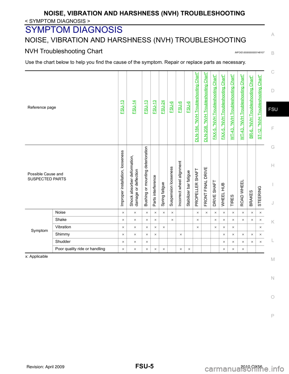
NVH Troubleshooting ChartINFOID:0000000005148107
Use the chart below to help you find the cause of the symptom. Repair or replace parts as necessary.
x: ApplicableReference page
FSU-13FSU-14FSU-13FSU-13FSU-24FSU-6FSU-6FSU-6
DLN-184, "
NVH Troubleshooting Chart
"
DLN-208, "
NVH Troubleshooting Chart
"
FAX-5, "
NVH Troubleshooting Chart
"
FAX-5, "
NVH Troubleshooting Chart
"
WT-43, "
NVH Troubleshooting Chart
"
WT-43, "
NVH Troubleshooting Chart
"
BR-6, "
NVH Troubleshooting Chart
"
ST-12, "
NVH Troubleshooting Chart
"
Possible Cause and
SUSPECTED PARTS
Improper installation, looseness
Shock absorber deformation,
damage or deflection
Bushing or mounting deterioration
Parts interference
Spring fatigue
Suspension looseness
Incorrect wheel alignment
Stabilizer bar fatigue
PROPELLER SHAFT
FRONT FINAL DRIVE
DRIVE SHAFT
WHEEL HUB
TIRES
ROAD WHEEL
BRAKES
STEERING
Symptom
Noise
× × ×××× × × ×× × × ××
Shake × × ×× × × ×× × × ××
Vibration × × ××× × ×× × ×
Shimmy × × ×× × × × × ××
Shudder ××× ×××××
Poor quality ride or handling × × ××× ×× × × ×
Revision: April 20092010 QX56
Page 2555 of 4210
SQUEAK AND RATTLE TROUBLE DIAGNOSESINT-3
< SYMPTOM DIAGNOSIS >
C
DE
F
G H
I
K L
M A
B
INT
N
O P
If possible, drive the vehicle with the customer until the noise is duplicated. Note any additional information on
the Diagnostic Worksheet regarding the conditions or lo cation of the noise. This information can be used to
duplicate the same conditions when you confirm the repair.
If the noise can be duplicated easily during the test drive, to help identify the source of the noise, try to dupli-
cate the noise with the vehicle stopped by doing one or all of the following:
1) Close a door.
2) Tap or push/pull around the area where the noise appears to be coming from.
3) Rev the engine.
4) Use a floor jack to recreate vehicle “twist”.
5) At idle, apply engine load. With brakes applied, place A/T shift selector in drive position.
6) Raise the vehicle on a hoist and hit a tire with a rubber hammer.
• Drive the vehicle and attempt to duplicate the conditions the customer states exist when the noise occurs.
• If it is difficult to duplicate the noise, drive the vehicle slowly on an undulating or rough road to stress the
vehicle body.
CHECK RELATED SERVICE BULLETINS
After verifying the customer concern or symptom, check ASIST for Technical Service Bulletins (TSBs) related
to that concern or symptom.
If a TSB relates to the symptom, follow the procedure to repair the noise.
LOCATE THE NOISE AND IDENTIFY THE ROOT CAUSE
1. Narrow down the noise to a general area.To help pinpoint the source of the noise, use a listening tool (Chassis Ear: J-39570, Engine Ear: J-39565 and mechanic's stethoscope).
2. Narrow down the noise to a more specific area and identify the cause of the noise by:
• removing the components in the area that you suspect the noise is coming from. Do not use too much force when removing clips and fasteners, otherwise clips and fasteners can be broken
or lost during the repair, resulting in the creation of new noise.
• tapping or pushing/pulling the component that you suspect is causing the noise.
Do not tap or push/pull the component with excessive force, otherwise the noise will be eliminated only tem-
porarily.
• feeling for a vibration with your hand by touching the component(s) that you suspect is (are) causing the
noise.
• placing a piece of paper between components that you suspect are causing the noise.
• looking for loose components and contact marks. Refer to INT-4, "
Generic Squeak and Rattle Troubleshooting".
REPAIR THE CAUSE
• If the cause is a loose component, tighten the component securely.
• If the cause is insufficient clearance between components:
- separate components by repositioning or loos ening and retightening the component, if possible.
- insulate components with a suitable insulator such as urethane pads, foam blocks, felt cloth tape or urethane tape. A NISSAN Squeak and Rattle Kit (J-43980) is available through your authorized NISSAN Parts Depart-
ment.
CAUTION:
Do not use excessive force as many components are constructed of plastic and may be damaged.
Always check with the Parts Department for the latest parts information.
The following materials are contained in the NISSAN Squeak and Rattle Kit (J-43980). Each item can be
ordered separately as needed.
URETHANE PADS [1.5 mm (0.059 in) thick]
Insulates connectors, harness, etc.
76268-9E005: 100 ×135 mm (3.94 ×5.31 in)/76884-71L01: 60 ×85 mm (2.36× 3.35 in)/76884-71L02: 15× 25
mm (0.59 ×0.98 in)
INSULATOR (Foam blocks)
Insulates components from contact. Can be used to fill space behind a panel.
73982-9E000: 45 mm (1.77 in) thick, 50× 50 mm (1.97×1.97 in)/73982-50Y00: 10 mm (0.39 in) thick,
50× 50 mm (1.97 ×1.97 in)
INSULATOR (Light foam block)
80845-71L00: 30 mm (1.18 in) thick, 30 ×50 mm (1.18 ×1.97 in)
FELT CLOTH TAPE
Used to insulate where movement does not occu r. Ideal for instrument panel applications.
Revision: April 20092010 QX56
Page 2579 of 4210
IP-6
< SYMPTOM DIAGNOSIS >
SQUEAK AND RATTLE TROUBLE DIAGNOSES
If possible, drive the vehicle with the customer until the noise is duplicated. Note any additional information on
the Diagnostic Worksheet regarding the conditions or lo cation of the noise. This information can be used to
duplicate the same conditions when you confirm the repair.
If the noise can be duplicated easily during the test drive, to help identify the source of the noise, try to dupli-
cate the noise with the vehicle stopped by doing one or all of the following:
1) Close a door.
2) Tap or push/pull around the area where the noise appears to be coming from.
3) Rev the engine.
4) Use a floor jack to recreate vehicle “twist”.
5) At idle, apply engine load. With brakes appllied, place A/T shift selector in drive position.
6) Raise the vehicle on a hoist and hit a tire with a rubber hammer.
• Drive the vehicle and attempt to duplicate the conditions the customer states exist when the noise occurs.
• If it is difficult to duplicate the noise, drive the v ehicle slowly on an undulating or rough road to stress the
vehicle body.
CHECK RELATED SERVICE BULLETINS
After verifying the customer concern or symptom, chec k ASIST for Technical Service Bulletins (TSBs) related
to that concern or symptom.
If a TSB relates to the symptom, follo w the procedure to repair the noise.
LOCATE THE NOISE AND IDENTIFY THE ROOT CAUSE
1. Narrow down the noise to a general area. To help pi npoint the source of the noise, use a listening tool
(Chassis Ear: J-39570, Engine Ear and mechanics stethoscope).
2. Narrow down the noise to a more specific area and identify the cause of the noise by:
• removing the components in the area that you suspect the noise is coming from.
Do not use too much force when removing clips and fasteners, otherwise clips and fastener can be broken
or lost during the repair, resulting in the creation of new noise.
• tapping or pushing/pulling the component that you suspect is causing the noise.
Do not tap or push/pull the component with excessive force, otherwise the noise will be eliminated only tem-
porarily.
• feeling for a vibration with your hand by touching the component(s) that you suspect is (are) causing the
noise.
• placing a piece of paper between components that you suspect are causing the noise.
• looking for loose components and contact marks. Refer to IP-7, "
Generic Squeak and Rattle Troubleshooting".
REPAIR THE CAUSE
• If the cause is a loose component, tighten the component securely.
• If the cause is insufficient clearance between components:
- separate components by repositioning or loos ening and retightening the component, if possible.
- insulate components with a suitable insulator such as urethane pads, foam blocks, felt cloth tape or urethane tape. A Nissan Squeak and Rattle Kit (J-43980) is available through your authorized Nissan Parts Depart-
ment.
CAUTION:
Do not use excessive force as many components are constructed of plastic and may be damaged.
NOTE:
Always check with the Parts Departm ent for the latest parts information.
The following materials are contained in the Nissan Squeak and Rattle Kit (J-43980). Each item can be
ordered separately as needed.
URETHANE PADS [1.5 mm (0.059 in) thick]
Insulates connectors, harness, etc.
76268-9E005: 100 ×135 mm (3.94 ×5.31 in)/76884-71L01: 60 ×85 mm (2.36 ×3.35 in)/76884-
71L02: 15 ×25 mm (0.59 ×0.98 in)
INSULATOR (Foam blocks)
Insulates components from contact. Can be used to fill space behind a panel.
73982-9E000: 45 mm (1.77 in) thick, 50 ×50 mm (1.97 ×1.97 in)/73982-
50Y00: 10 mm (0.39 in) thick, 50 ×50 mm (1.97 ×1.97 in)
INSULATOR (Light foam block)
80845-71L00: 30 mm (1.18 in) thick, 30 ×50 mm (1.18 ×1.97 in)
FELT CLOTHTAPE
Used to insulate where movement does not occu r. Ideal for instrument panel applications.
Revision: April 20092010 QX56
Page 2711 of 4210
GENERAL MAINTENANCEMA-7
< ON-VEHICLE MAINTENANCE >
C
DE
F
G H
I
J
K L
M B
MA
N
O A
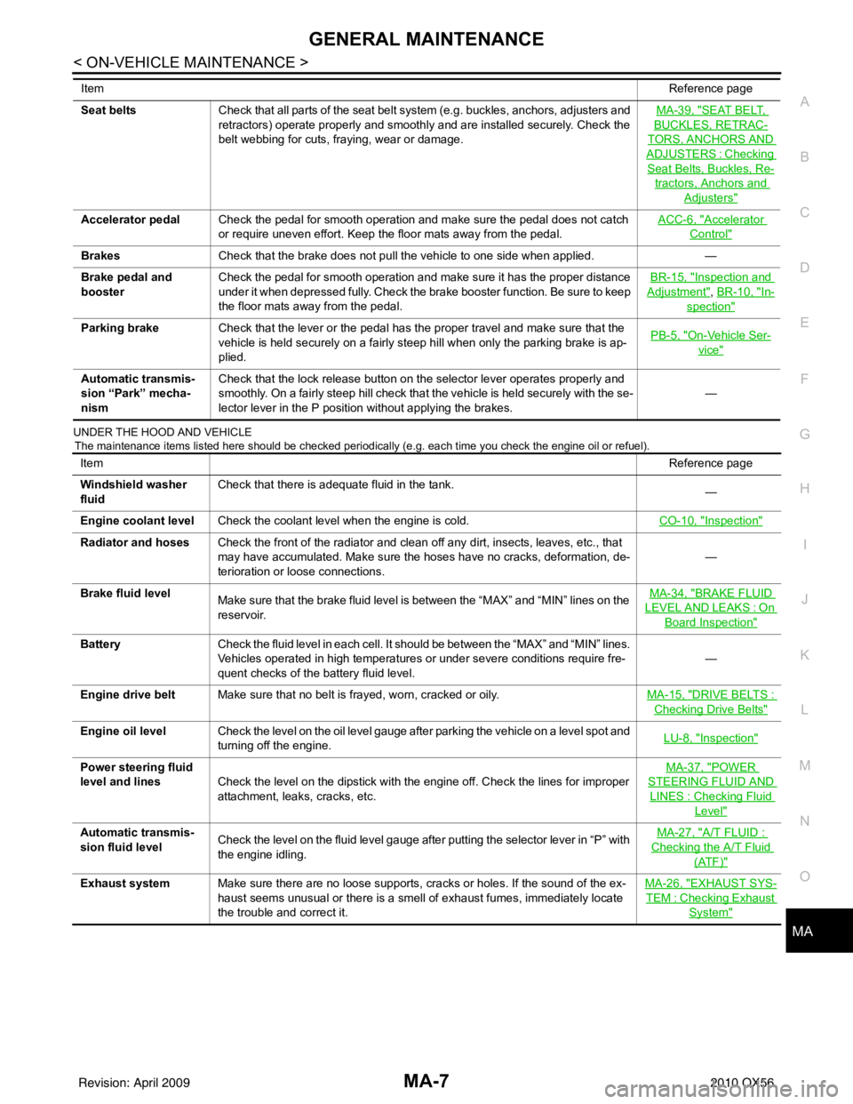
UNDER THE HOOD AND VEHICLE
The maintenance items listed here should be checked periodically (e.g. each time you check the engine oil or refuel).
Seat beltsCheck that all parts of the seat belt system (e.g. buckles, anchors, adjusters and
retractors) operate properly and smoothly and are installed securely. Check the
belt webbing for cuts, fraying, wear or damage. MA-39, "SEAT BELT,
BUCKLES, RETRAC-
TORS, ANCHORS AND
ADJUSTERS : Checking
Seat Belts, Buckles, Re-
tractors, Anchors and
Adjusters"
Accelerator pedal
Check the pedal for smooth operation and make sure the pedal does not catch
or require uneven effort. Keep the floor mats away from the pedal. ACC-6, "Accelerator
Control"
Brakes
Check that the brake does not pull the vehicle to one side when applied. —
Brake pedal and
booster Check the pedal for smooth operation and make sure it has the proper distance
under it when depressed fully. Check the brake booster function. Be sure to keep
the floor mats away from the pedal. BR-15, "
Inspection and
Adjustment", BR-10, "In-
spection"
Parking brake
Check that the lever or the pedal has the proper travel and make sure that the
vehicle is held securely on a fairly steep hill when only the parking brake is ap-
plied. PB-5, "On-Vehicle Ser-
vice"
Automatic transmis-
sion “Park” mecha-
nismCheck that the lock release button on the selector lever operates properly and
smoothly. On a fairly steep hill check that the vehicle is held securely with the se-
lector lever in the P position without applying the brakes.
—
Item
Reference page
Item Reference page
Windshield washer
fluid Check that there is adequate fluid in the tank.
—
Engine coolant level Check the coolant level when the engine is cold. CO-10, "
Inspection"
Radiator and hosesCheck the front of the radiator and clean off any dirt, insects, leaves, etc., that
may have accumulated. Make sure the hoses have no cracks, deformation, de-
terioration or loose connections. —
Brake fluid level Make sure that the brake fluid level is between the “MAX” and “MIN” lines on the
reservoir. MA-34, "
BRAKE FLUID
LEVEL AND LEAKS : On
Board Inspection"
Battery
Check the fluid level in each cell. It should be between the “MAX” and “MIN” lines.
Vehicles operated in high temperatures or under severe conditions require fre-
quent checks of the battery fluid level. —
Engine drive belt Make sure that no belt is frayed, worn, cracked or oily. MA-15, "
DRIVE BELTS :
Checking Drive Belts"
Engine oil levelCheck the level on the oil level gauge after parking the vehicle on a level spot and
turning off the engine. LU-8, "Inspection"
Power steering fluid
level and lines
Check the level on the dipstick with the engine off. Check the lines for improper
attachment, leaks, cracks, etc. MA-37, "POWER
STEERING FLUID AND
LINES : Checking Fluid
Level"
Automatic transmis-
sion fluid level
Check the level on the fluid level gauge after putting the selector lever in “P” with
the engine idling. MA-27, "A/T FLUID :
Checking the A/T Fluid
(ATF)"
Exhaust system
Make sure there are no loose supports, cracks or holes. If the sound of the ex-
haust seems unusual or there is a smell of exhaust fumes, immediately locate
the trouble and correct it. MA-26, "EXHAUST SYS-
TEM : Checking Exhaust
System"
Revision: April 20092010 QX56
Page 2864 of 4210

PB-1
BRAKES
C
DE
G H
I
J
K L
M
SECTION PB
A
B
PB
N
O P
CONTENTS
PARKING BRAKE SYSTEM
PRECAUTION ....... ........................................2
PRECAUTIONS .............................................. .....2
Precaution for Supplemental Restraint System
(SRS) "AIR BAG" and "SEAT BELT PRE-TEN-
SIONER" ............................................................. ......
2
Precaution Necessary for Steering Wheel Rota-
tion After Battery Disconnect ............................... ......
2
PREPARATION ............................................4
PREPARATION .............................................. .....4
Commercial Service Tool .................................... ......4
ON-VEHICLE MAINTENANCE .....................5
PARKING BRAKE SYSTEM .......................... .....5
On-Vehicle Service ............................................. ......5
ON-VEHICLE REPAIR ..................................7
PARKING BRAKE CONTROL ...........................7
Component .......................................................... .....7
Removal and Installation ..........................................7
PARKING BRAKE SHOE ..................................9
Removal and Installation ..........................................9
SERVICE DATA AND SPECIFICATIONS
(SDS) ............... .......................................... ...
12
SERVICE DATA AND SPECIFICATIONS
(SDS) .................................................................
12
Parking Brake ...................................................... ....12
Parking Brake Control .............................................12
Revision: April 20092010 QX56
Page 2872 of 4210
PARKING BRAKE SHOEPB-9
< ON-VEHICLE REPAIR >
C
DE
G H
I
J
K L
M A
B
PB
N
O P
PARKING BRAKE SHOE
Removal and InstallationINFOID:0000000005147935
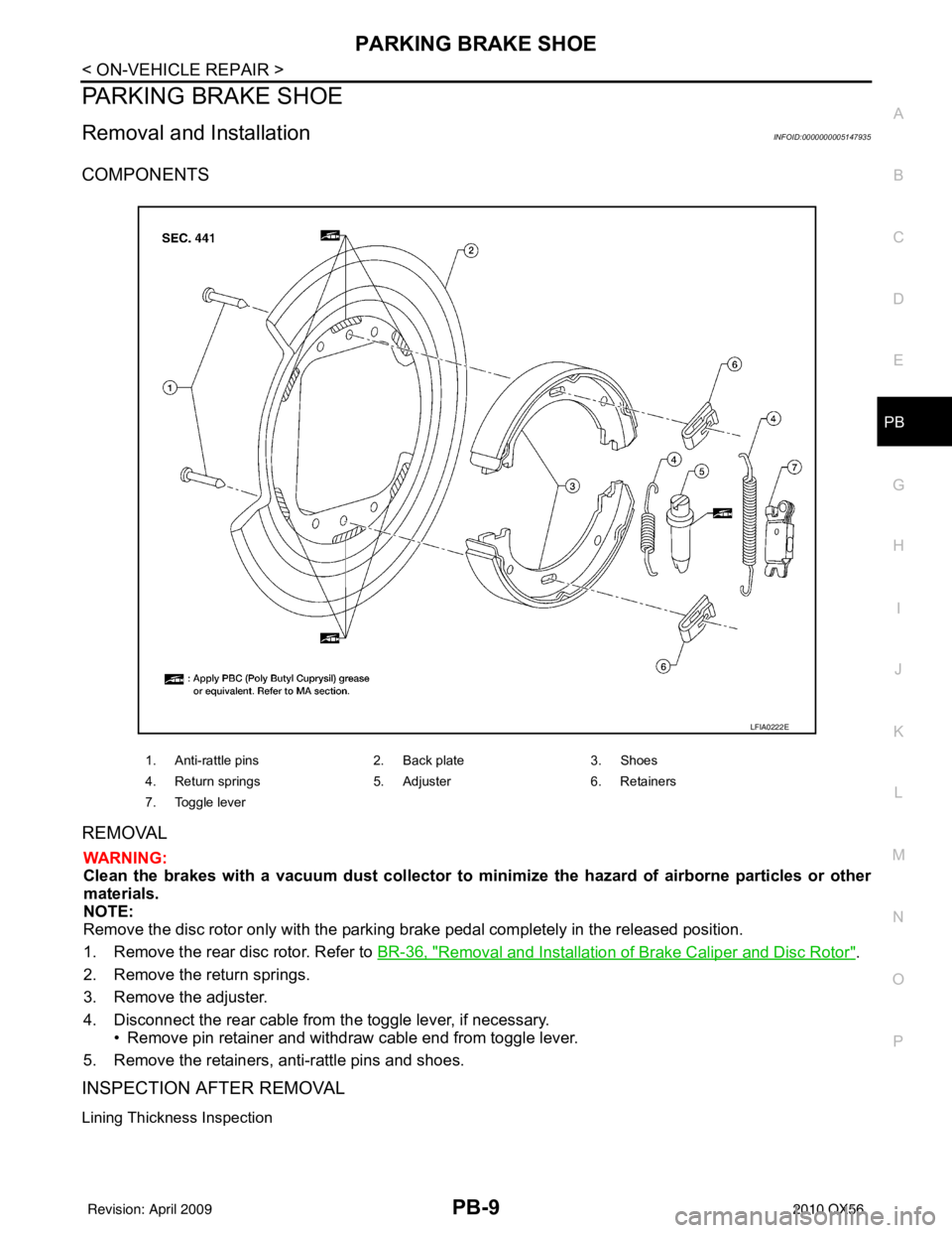
COMPONENTS
REMOVAL
WARNING:
Clean the brakes with a vacuum dust co llector to minimize the hazard of airborne particles or other
materials.
NOTE:
Remove the disc rotor only with the parking brake pedal completely in the released position.
1. Remove the rear disc rotor. Refer to BR-36, "
Removal and Installation of Brake Caliper and Disc Rotor".
2. Remove the return springs.
3. Remove the adjuster.
4. Disconnect the rear cable from the toggle lever, if necessary.
• Remove pin retainer and withdraw cable end from toggle lever.
5. Remove the retainers, anti-rattle pins and shoes.
INSPECTION AFTER REMOVAL
Lining Thickness Inspection
1. Anti-rattle pins 2. Back plate3. Shoes
4. Return springs 5. Adjuster6. Retainers
7. Toggle lever
LFIA0222E
Revision: April 20092010 QX56