2010 INFINITI QX56 boot
[x] Cancel search: bootPage 2716 of 4210
MA-12
< ON-VEHICLE MAINTENANCE >
PERIODIC MAINTENANCE
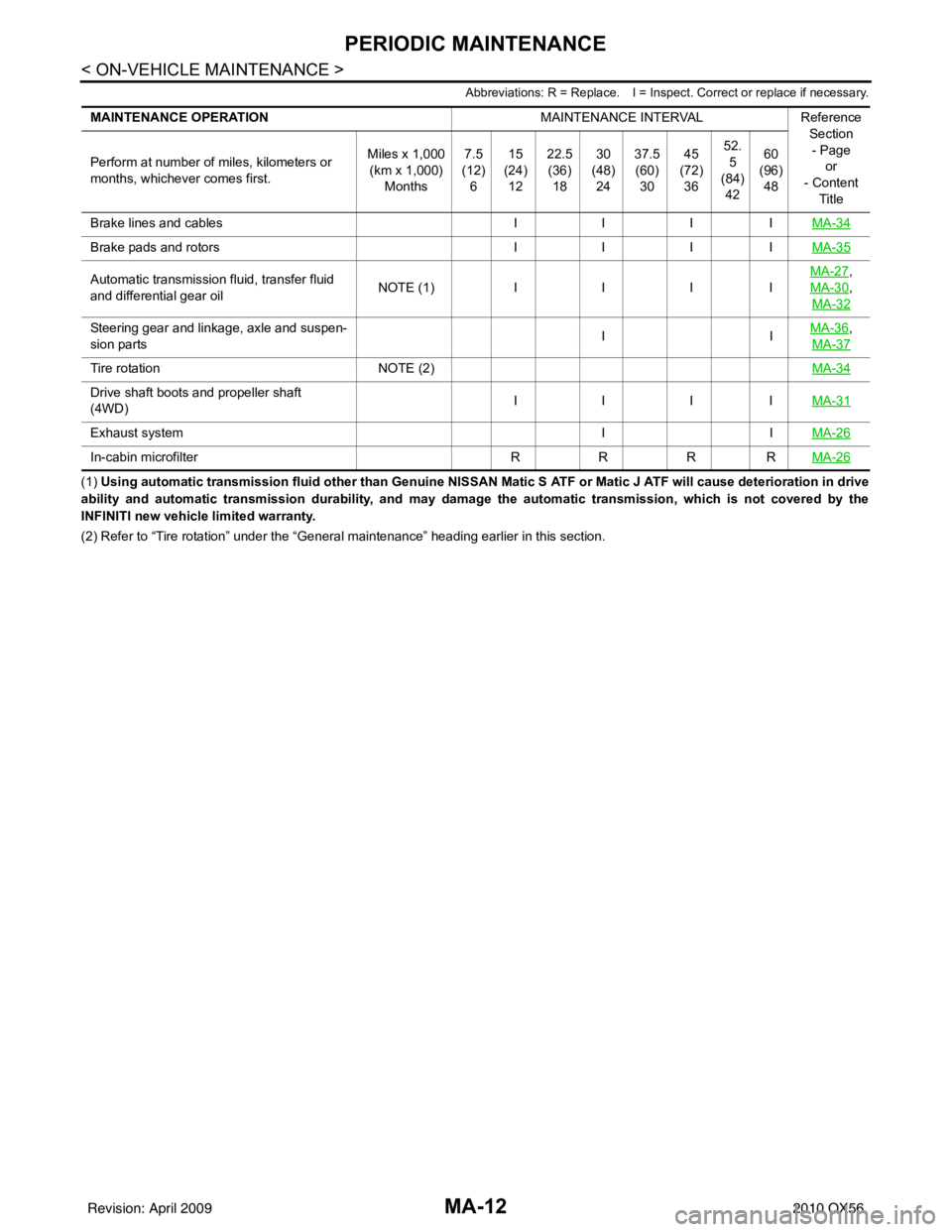
Abbreviations: R = Replace. I = Inspect. Correct or replace if necessary.
(1) Using automatic transmission fluid other than Genuine NISSAN Matic S ATF or Matic J ATF will cause deterioration in drive
ability and automatic transmission durability, and may damage the automatic transmission, which is not covered by the
INFINITI new vehicle limited warranty.
(2) Refer to “Tire rotation” unde r the “General maintenance” heading earlier in this section.
MAINTENANCE OPERATION
MAINTENANCE INTERVALReference
Section
- Page or
- Content
Title
Perform at number of miles, kilometers or
months, whichever comes first.
Miles x 1,000
(km x 1,000)
Months 7.5
(12)
6 15
(24)
12 22.5
(36)
18 30
(48)
24 37.5
(60)
30 45
(72)
36 52.
5
(84) 42 60
(96)
48
Brake lines and cables IIIIMA-34
Brake pads and rotors IIIIMA-35
Automatic transmission fluid, transfer fluid
and differential gear oil N
O TE (1)IIII MA-27,
MA-30
,
MA-32
Steering gear and linkage, axle and suspen-
sion parts IIMA-36,
MA-37
Tire rotation NOTE (2) MA-34
Drive shaft boots and propeller shaft
(4WD)IIII
MA-31
Exhaust system IIMA-26
In-cabin microfilter RRRRMA-26
Revision: April 20092010 QX56
Page 2741 of 4210
CHASSIS AND BODY MAINTENANCEMA-37
< ON-VEHICLE MAINTENANCE >
C
DE
F
G H
I
J
K L
M B
MA
N
O A
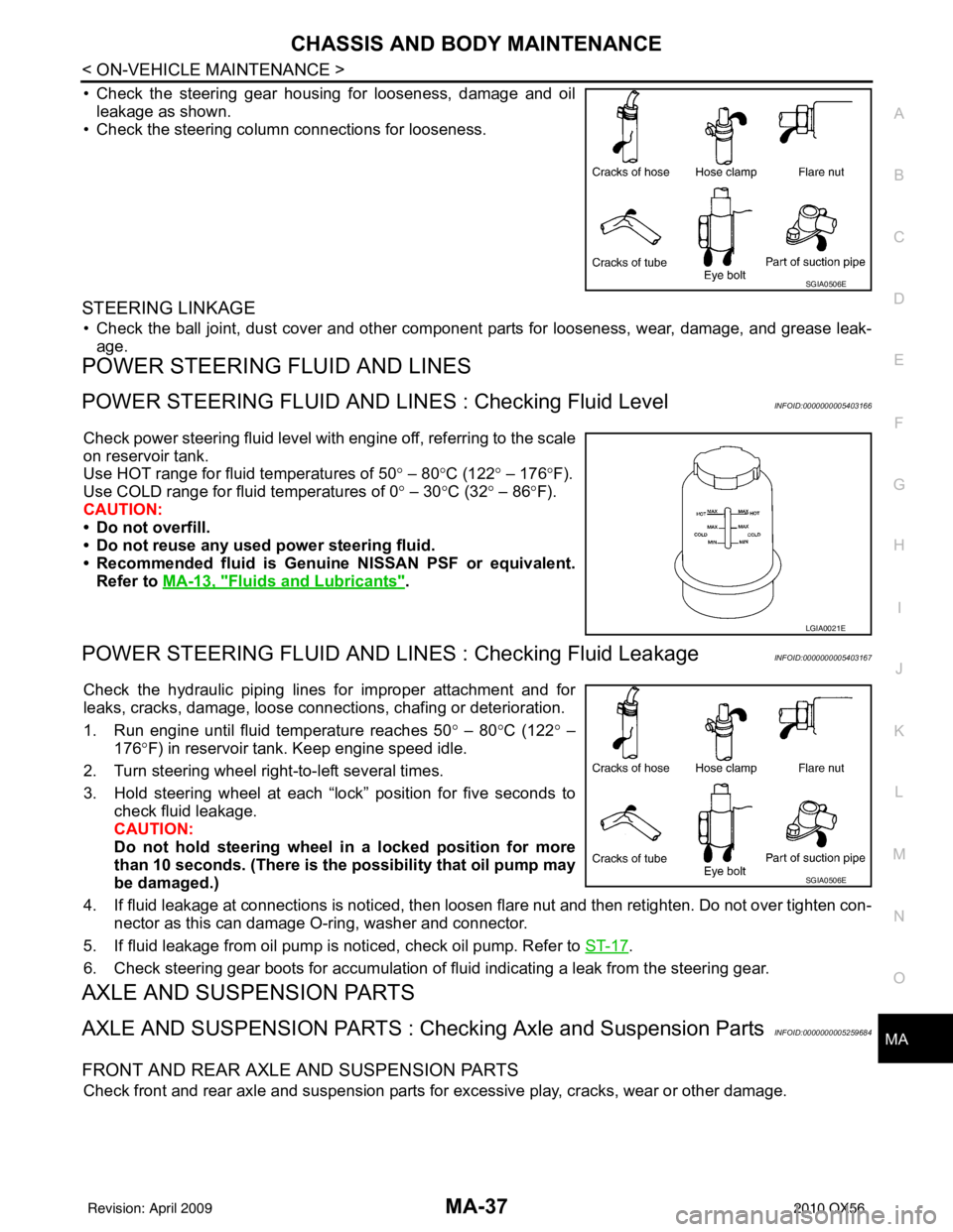
• Check the steering gear housing for looseness, damage and oil
leakage as shown.
• Check the steering column connections for looseness.
STEERING LINKAGE
• Check the ball joint, dust cover and other component parts for looseness, wear, damage, and grease leak-
age.
POWER STEERING FLUID AND LINES
POWER STEERING FLUID AND LINE S : Checking Fluid LevelINFOID:0000000005403166
Check power steering fluid level with engine off, referring to the scale
on reservoir tank.
Use HOT range for fluid temperatures of 50 ° – 80 °C (122 ° – 176 °F).
Use COLD range for fluid temperatures of 0 ° – 30 °C (32° – 86°F).
CAUTION:
• Do not overfill.
• Do not reuse any used power steering fluid.
• Recommended fluid is Genuine NISSAN PSF or equivalent.
Refer to MA-13, "
Fluids and Lubricants".
POWER STEERING FLUID AND LINES : Checking Fluid LeakageINFOID:0000000005403167
Check the hydraulic piping lines for improper attachment and for
leaks, cracks, damage, loose connec tions, chafing or deterioration.
1. Run engine until fluid temperature reaches 50 ° – 80° C (122° –
176° F) in reservoir tank. Keep engine speed idle.
2. Turn steering wheel right-to-left several times.
3. Hold steering wheel at each “lock” position for five seconds to check fluid leakage.
CAUTION:
Do not hold steering wheel in a locked position for more
than 10 seconds. (There is the possibility that oil pump may
be damaged.)
4. If fluid leakage at connections is noticed, then loosen flare nut and then retighten. Do not over tighten con- nector as this can damage O-ring, washer and connector.
5. If fluid leakage from oil pump is noticed, check oil pump. Refer to ST-17
.
6. Check steering gear boots for accumulation of fluid indicating a leak from the steering gear.
AXLE AND SUSPENSION PARTS
AXLE AND SUSPENSION PARTS : Chec king Axle and Suspension PartsINFOID:0000000005259684
FRONT AND REAR AXLE AND SUSPENSION PARTS
Check front and rear axle and suspension parts for excessive play, cracks, wear or other damage.
SGIA0506E
LGIA0021E
SGIA0506E
Revision: April 20092010 QX56
Page 3113 of 4210
RAX-1
TRANSMISSION & DRIVELINE
CEF
G H
I
J
K L
M
SECTION RAX
A
B
RAX
N
O P
CONTENTS
REAR AXLE
PRECAUTION ....... ........................................2
PRECAUTIONS .............................................. .....2
Precaution for Supplemental Restraint System
(SRS) "AIR BAG" and "SEAT BELT PRE-TEN-
SIONER" ............................................................. ......
2
Precaution Necessary for Steering Wheel Rota-
tion After Battery Disconnect ............................... ......
2
Precaution .................................................................3
PREPARATION ............................................4
PREPARATION .............................................. .....4
Special Service Tool ........................................... ......4
Commercial Service Tool ..........................................4
SYMPTOM DIAGNOSIS ...............................5
NOISE, VIBRATION AND HARSHNESS
(NVH) TROUBLESHOOTING ........................ .....
5
NVH Troubleshooting Chart ................................ ......5
ON-VEHICLE MAINTENANCE .....................6
WHEEL HUB .................................................. .....6
On-Vehicle Inspection and Service ..................... ......6
ON-VEHICLE REPAIR ..................................7
REAR DRIVE SHAFT .........................................7
Component .......................................................... .....7
REMOVAL AND INSTALLATION ................8
WHEEL HUB ......................................................8
Removal and Installation ..................................... .....8
REAR DRIVE SHAFT ........................................10
Removal and Installation .........................................10
DISASSEMBLY AND ASSEMBLY ..............11
REAR DRIVE SHAFT ........................................11
Disassembly and Assembly ................................. ....11
SERVICE DATA AND SPECIFICATIONS
(SDS) ............... .......................................... ...
16
SERVICE DATA AND SPECIFICATIONS
(SDS) .................................................................
16
Wheel Bearing ..................................................... ....16
Drive Shaft ...............................................................16
Boot Bands ..............................................................16
Revision: April 20092010 QX56
Page 3116 of 4210
RAX-4
< PREPARATION >
PREPARATION
PREPARATION
PREPARATION
Special Service ToolINFOID:0000000005148951
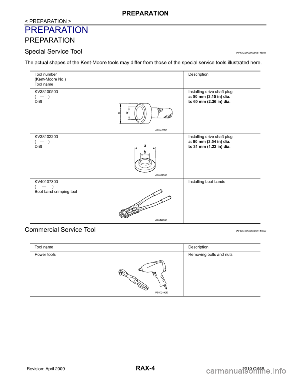
The actual shapes of the Kent-Moore tools may differ from those of the special service tools illustrated here.
Commercial Service ToolINFOID:0000000005148952
Tool number
(Kent-Moore No.)
Tool name Description
KV38100500
(—)
Drift Installing drive shaft plug
a: 80 mm (3.15 in) dia.
b: 60 mm (2.36 in) dia.
KV38102200
(—)
Drift Installing drive shaft plug
a: 90 mm (3.54 in) dia.
b: 31 mm (1.22 in) dia.
KV40107300
(—)
Boot band crimping tool Installing boot bands
ZZA0701D
ZZA0920D
ZZA1229D
Tool name
Description
Power tools Removing bolts and nuts
PBIC0190E
Revision: April 20092010 QX56
Page 3122 of 4210
RAX-10
< REMOVAL AND INSTALLATION >
REAR DRIVE SHAFT
REAR DRIVE SHAFT
Removal and InstallationINFOID:0000000005148957
REMOVAL
1. Remove the wheel and tire using power tool.
2. Remove the stabilizer bar clamp. Refer to RSU-9, "
Component".
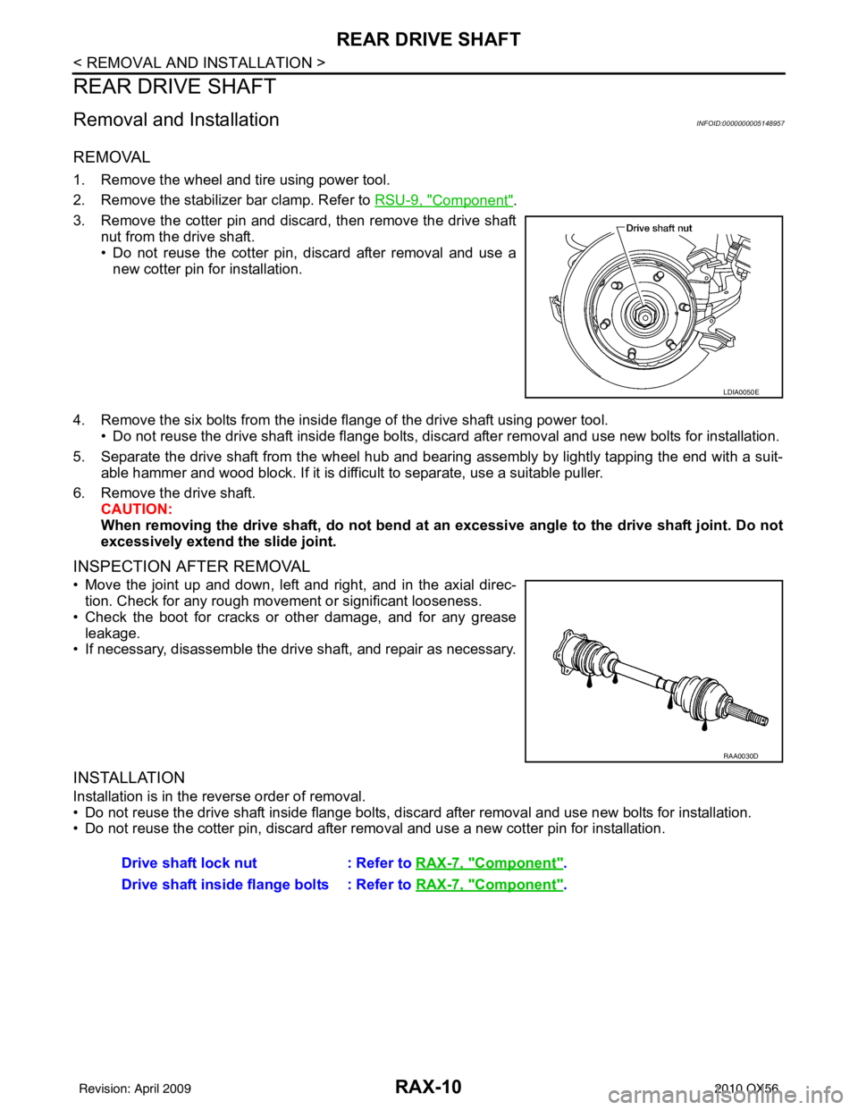
3. Remove the cotter pin and discard, then remove the drive shaft nut from the drive shaft.
• Do not reuse the cotter pin, discard after removal and use anew cotter pin for installation.
4. Remove the six bolts from the inside flange of the drive shaft using power tool. • Do not reuse the drive shaft inside flange bolts, discard after removal and use new bolts for installation.
5. Separate the drive shaft from the wheel hub and bearing assembly by lightly tapping the end with a suit- able hammer and wood block. If it is difficult to separate, use a suitable puller.
6. Remove the drive shaft. CAUTION:
When removing the drive shaft, do not bend at an excessive angle to the drive shaft joint. Do not
excessively extend the slide joint.
INSPECTION AFTER REMOVAL
• Move the joint up and down, left and right, and in the axial direc- tion. Check for any rough movement or significant looseness.
• Check the boot for cracks or other damage, and for any grease leakage.
• If necessary, disassemble the drive shaft, and repair as necessary.
INSTALLATION
Installation is in the reverse order of removal.
• Do not reuse the drive shaft inside flange bolts, discard after removal and use new bolts for installation.
• Do not reuse the cotter pin, discard after removal and use a new cotter pin for installation.
LDIA0050E
RAA0030D
Drive shaft lock nut : Refer to RAX-7, "Component".
Drive shaft inside flange bolts : Refer to RAX-7, "
Component".
Revision: April 20092010 QX56
Page 3123 of 4210
REAR DRIVE SHAFTRAX-11
< DISASSEMBLY AND ASSEMBLY >
CEF
G H
I
J
K L
M A
B
RAX
N
O P
DISASSEMBLY AND ASSEMBLY
REAR DRIVE SHAFT
Disassembly and AssemblyINFOID:0000000005274245
DISASSEMBLY
Final Drive Side
1. Secure the drive shaft in a vise. CAUTION:
When securing the drive shaft in a vise, use copper or aluminum plates between the vise and the
drive shaft.
2. Remove the boot bands.
3. If the plug needs to be removed, move the boot to t he wheel side, then drive the plug out using a suitable
tool.
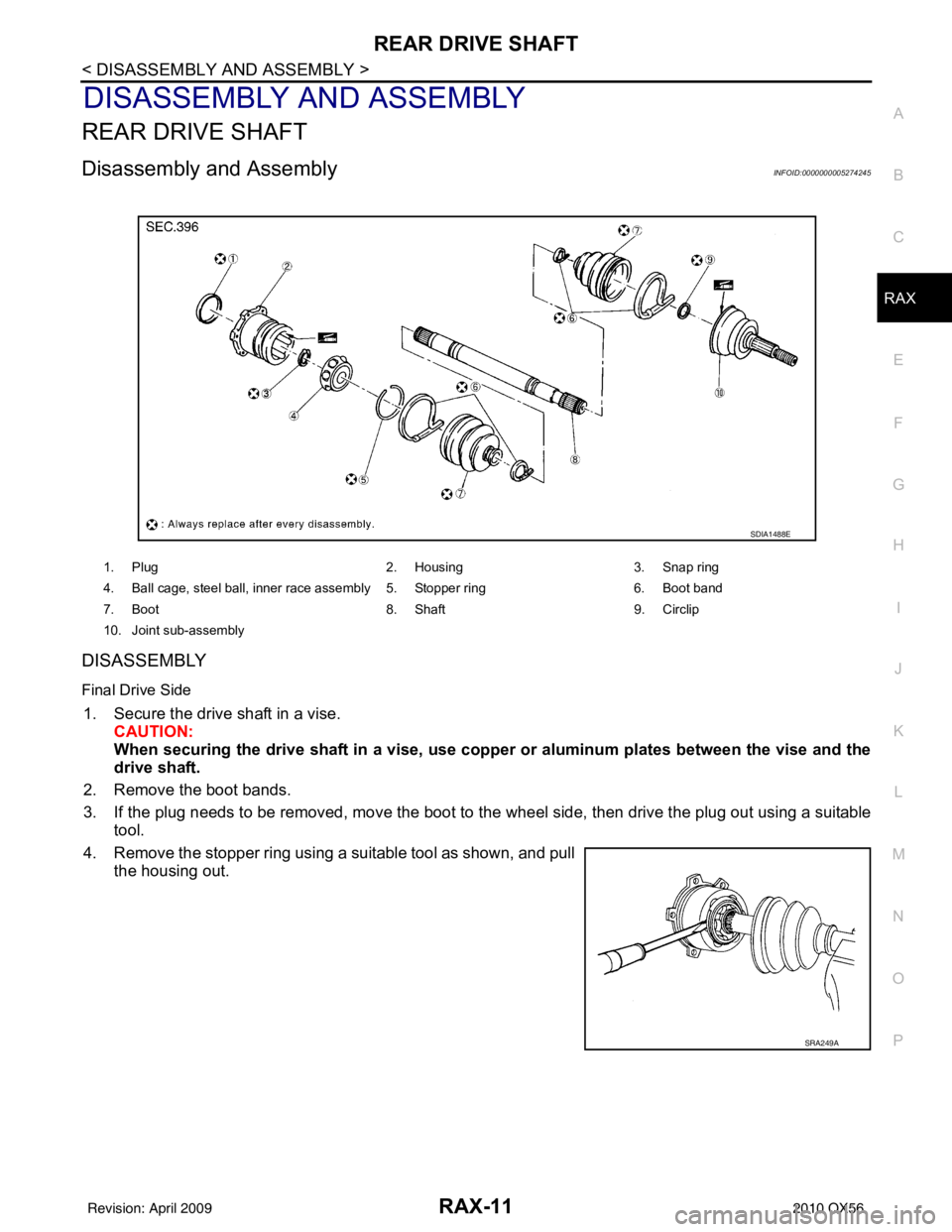
4. Remove the stopper ring using a suitable tool as shown, and pull the housing out.
1. Plug 2. Housing3. Snap ring
4. Ball cage, steel ball, inner race assembly 5. Stopper ring 6. Boot band
7. Boot 8. Shaft9. Circlip
10. Joint sub-assembly
SDIA1488E
SRA249A
Revision: April 20092010 QX56
Page 3124 of 4210
RAX-12
< DISASSEMBLY AND ASSEMBLY >
REAR DRIVE SHAFT
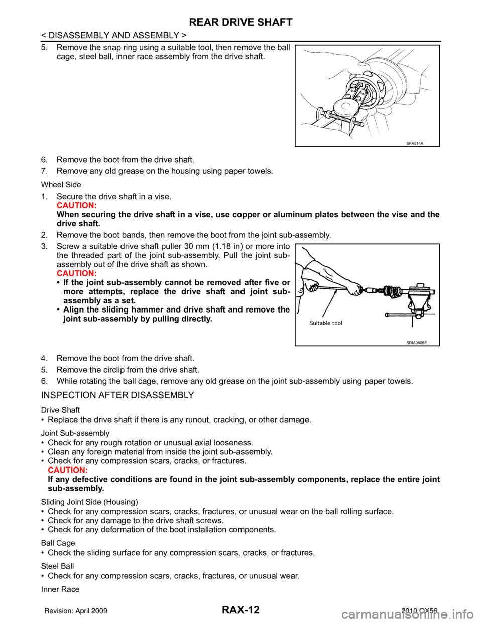
5. Remove the snap ring using a suitable tool, then remove the ballcage, steel ball, inner race assembly from the drive shaft.
6. Remove the boot from the drive shaft.
7. Remove any old grease on the housing using paper towels.
Wheel Side
1. Secure the drive shaft in a vise. CAUTION:
When securing the drive shaft in a vise, use copp er or aluminum plates between the vise and the
drive shaft.
2. Remove the boot bands, then remove the boot from the joint sub-assembly.
3. Screw a suitable drive shaft puller 30 mm (1.18 in) or more into the threaded part of the joint sub-assembly. Pull the joint sub-
assembly out of the drive shaft as shown.
CAUTION:
• If the joint sub-assembly cannot be removed after five ormore attempts, replace the drive shaft and joint sub-
assembly as a set.
• Align the sliding hammer and drive shaft and remove the
joint sub-assembly by pulling directly.
4. Remove the boot from the drive shaft.
5. Remove the circlip from the drive shaft.
6. While rotating the ball cage, remove any old grease on the joint sub-assembly using paper towels.
INSPECTION AFTER DISASSEMBLY
Drive Shaft
• Replace the drive shaft if there is any runout, cracking, or other damage.
Joint Sub-assembly
• Check for any rough rotation or unusual axial looseness.
• Clean any foreign material from inside the joint sub-assembly.
• Check for any compression scars, cracks, or fractures.
CAUTION:
If any defective conditions are found in the joint sub-assembly comp onents, replace the entire joint
sub-assembly.
Sliding Joint Side (Housing)
• Check for any compression scars, cracks, fracture s, or unusual wear on the ball rolling surface.
• Check for any damage to the drive shaft screws.
• Check for any deformation of the boot installation components.
Ball Cage
• Check the sliding surface for any compression scars, cracks, or fractures.
Steel Ball
• Check for any compression scars, cr acks, fractures, or unusual wear.
Inner Race
SFA514A
SDIA0606E
Revision: April 20092010 QX56
Page 3125 of 4210
REAR DRIVE SHAFTRAX-13
< DISASSEMBLY AND ASSEMBLY >
CEF
G H
I
J
K L
M A
B
RAX
N
O P
• Check the ball sliding surface for any co mpression scars, cracks, or fractures.
• Check for any damage to the serrated part. CAUTION:
If any defective conditions are found, install a new housing, ball cage, steel ball, and inner race as a
set.
ASSEMBLY
Final Drive Side
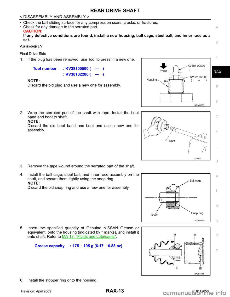
1. If the plug has been removed, use Tool to press in a new one.
NOTE:
Discard the old plug and use a new one for assembly.
2. Wrap the serrated part of the shaft with tape. Install the boot band and boot to shaft.
NOTE:
Discard the old boot band and boot and use a new one for
assembly.
3. Remove the tape wound around the serrated part of the shaft.
4. Install the ball cage, steel ball, and inner race assembly on the shaft, and secure them tightly using the snap ring.
NOTE:
Discard the old snap ring and use a new one for assembly.
5. Insert the specified quantity of Genuine NISSAN Grease or equivalent, onto the housing (indicated by * marks), and install it
onto shaft. Refer to MA-13, "
Fluids and Lubricants".
6. Install the stopper ring onto the housing. Tool number : KV38100500 ( — )
: KV38102200 ( — )
SDIA1153E
SFA800
SDIA1125E
Grease capacity : 175 − 195 g (6.17 − 6.88 oz)
RAC0678D
Revision: April 20092010 QX56