Page 487 of 4210
BR-42
< DISASSEMBLY AND ASSEMBLY >
REAR DISC BRAKE
REAR DISC BRAKE
Disassembly and AssemblyINFOID:0000000005147924
DISASSEMBLY
1. Remove pads from cylinder body.
2. Remove sliding sleeve and boot from cylinder body.
3. Place a wooden block as shown, and blow air into union bolthole to remove piston and piston boot.
CAUTION:
Do not get your fingers caught in piston.
1. Union bolt 2. Brake hose3. Copper washer
4. Cap 5. Bleed valve6. Sliding pin bolt
7. Cylinder body 8. Piston seal9. Piston
10. Piston boot 11. Knuckle slide12. Sliding sleeve boot
13. Sliding sleeve B. Brake fluidR. Rubber grease
M. Molykote M-77 Front
AWFIA0423GB
BRD0041D
Revision: April 20092010 QX56
Page 488 of 4210

REAR DISC BRAKEBR-43
< DISASSEMBLY AND ASSEMBLY >
C
DE
G H
I
J
K L
M A
B
BR
N
O P
4. Using a suitable tool, remove piston seal from cylinder body as shown.
CAUTION:
Be careful not to damage cylinder body inner wall.
5. Remove the bleeder valve and cap.
CALIPER INSPECTION
Cylinder Body
Check inside surface of cylinder body for score, rust wear, damage or foreign materials. If any of the above
conditions are observed, replace cylinder body.
Minor damage from rust or foreign materials may be eliminated by polishing surface with a fine emery paper.
Replace cylinder body if necessary.
CAUTION:
• Use new brake fluid to clean. Do not use mi neral oils such as gasoline or kerosene.
Torque Member
Check for wear, cracks, and damage. If damage or deformation is present, replace the affected part.
Piston
Check piston for score, rust, wear, damage or presence of foreign materials. Replace if any of the above con-
ditions are observed.
CAUTION:
• Piston sliding surface is plated, do not polish with emery paper even if rust of foreign materials are
stuck to sliding surface.
Sliding Pin Bolts and Sliding Pin Boots
Make sure there is no wear, damage, or cracks in sliding sleeve and sliding sleeve boots, and if there are,
replace them.
ASSEMBLY
CAUTION:
Do not use NISSAN Rubber Grease ( KRE00 00010, KRE00 00010 01) when assembling.
1. Install the bleeder valve and cap.
2. Apply clean brake fluid to new piston seal and insert in to groove on cylinder body.
CAUTION:
Do not reuse piston seal.
PFIA0269E
WFIA0210E
Revision: April 20092010 QX56
Page 489 of 4210
BR-44
< DISASSEMBLY AND ASSEMBLY >
REAR DISC BRAKE
3. Apply clean brake fluid to piston and to piston boot, then installpiston boot in to piston groove.
CAUTION:
Do not reuse piston boot.
4. Insert into cylinder body by hand and insert piston boot piston-side lip into piston groove. CAUTION:
Press piston evenly and vary the pressing point to prevent cylinder body inner wall from being
rubbed.
5. Apply rubber grease to sliding sleeves, then install sliding boots and sleeves to cylinder body.
WFIA0211E
Revision: April 20092010 QX56
Page 2167 of 4210

FAX-1
TRANSMISSION & DRIVELINE
CEF
G H
I
J
K L
M
SECTION FA X
A
B
FA X
N
O P
CONTENTS
FRONT AXLE
PRECAUTION ....... ........................................2
PRECAUTIONS .............................................. .....2
Precaution for Supplemental Restraint System
(SRS) "AIR BAG" and "SEAT BELT PRE-TEN-
SIONER" ............................................................. ......
2
Precaution Necessary for Steering Wheel Rota-
tion After Battery Disconnect ............................... ......
2
Precaution .................................................................3
PREPARATION ............................................4
PREPARATION .............................................. .....4
Special Service Tool ........................................... ......4
Commercial Service Tool ..........................................4
SYMPTOM DIAGNOSIS ...............................5
NOISE, VIBRATION AND HARSHNESS
(NVH) TROUBLESHOOTING ........................ .....
5
NVH Troubleshooting Chart ................................ ......5
ON-VEHICLE MAINTENANCE .....................6
WHEEL HUB ......................................................6
On-Vehicle Inspection and Service ..................... .....6
REMOVAL AND INSTALLATION ................7
WHEEL HUB ......................................................7
Removal and Installation ..................................... .....7
DRIVE SHAFT ....................................................9
Removal and Installation ..........................................9
DISASSEMBLY AND ASSEMBLY ..............11
DRIVE SHAFT ...................................................11
Disassembly and Assembly ................................. ....11
SERVICE DATA AND SPECIFICATIONS
(SDS) ............... .......................................... ...
16
SERVICE DATA AND SPECIFICATIONS
(SDS) .................................................................
16
Wheel Bearing ..................................................... ....16
Drive Shaft ...............................................................16
Boot Bands ..............................................................16
Revision: April 20092010 QX56
Page 2170 of 4210
FAX-4
< PREPARATION >
PREPARATION
PREPARATION
PREPARATION
Special Service ToolINFOID:0000000005148940
The actual shapes of Kent-Moore tools may differ from those of special service tools illustrated here.
Commercial Service ToolINFOID:0000000005148941
Tool number
(Kent-Moore No.)
Tool name Description
ST29020001
(J-24319-01)
Gear arm puller Removing ball joint for steering knuckle
a: 34 mm (1.34 in)
b: 6.5 mm (0.256 in)
c: 61.5 mm (2.421 in)
KV40107300
(—)
Boot band crimping tool Installing boot bands
NT694
ZZA1229D
Tool name
Description
Power tools Removing bolts and nuts
PBIC0190E
Revision: April 20092010 QX56
Page 2176 of 4210
FAX-10
< REMOVAL AND INSTALLATION >
DRIVE SHAFT
• Check boot for cracks or other damage, and for grease leakage.
• If damaged, disassemble drive shaft to verify damage, and repairor replace as necessary.
INSTALLATION
Installation is in the reverse order of removal.
• Tighten wheel nuts to specification. Refer to WT-49, "
Rotation".
RAA0030D
Revision: April 20092010 QX56
Page 2177 of 4210
DRIVE SHAFTFAX-11
< DISASSEMBLY AND ASSEMBLY >
CEF
G H
I
J
K L
M A
B
FA X
N
O P
DISASSEMBLY AND ASSEMBLY
DRIVE SHAFT
Disassembly and AssemblyINFOID:0000000005148946
DISASSEMBLY
Final Drive Side
1. Mount the drive shaft in a vise. CAUTION:
When mounting the drive shaft in a vise, use co pper or aluminum plates between the vise and the
drive shaft.
2. Remove the boot bands.
3. Remove the stopper ring using suitable tool as shown, and pull the housing off.
1. Sliding joint housing 2. Snap ring 3. Ball cage, steel ball, inner race assembly
4. Stopper ring 5. Boot band6. Boot
7. Drive shaft 8. Circlip9. Joint sub-assembly
WDIA0054E
SRA249A
Revision: April 20092010 QX56
Page 2178 of 4210

FAX-12
< DISASSEMBLY AND ASSEMBLY >
DRIVE SHAFT
4. Remove the snap ring, then remove the ball cage, steel ball,inner race assembly from the drive shaft.
5. Remove the boot from the drive shaft.
6. Remove any old grease on the housing using paper towels.
Wheel Side
1. Mount the drive shaft in a vise. CAUTION:
When mounting the drive shaft in a vise, use copp er or aluminum plates between the vise and the
drive shaft.
2. Remove the boot bands, then remove the boot from the joint sub-assembly.
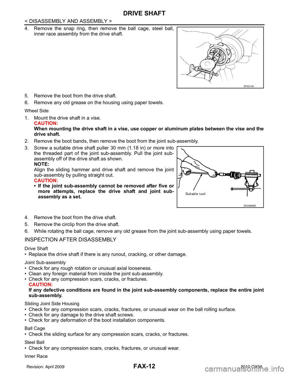
3. Screw a suitable drive shaft puller 30 mm (1.18 in) or more into the threaded part of the joint sub-assembly. Pull the joint sub-
assembly off of the drive shaft as shown.
NOTE:
Align the sliding hammer and drive shaft and remove the joint
sub-assembly by pulling straight out.
CAUTION:
• If the joint sub-assembly cannot be removed after five ormore attempts, replace the drive shaft and joint sub-
assembly as a set.
4. Remove the boot from the drive shaft.
5. Remove the circlip from the drive shaft.
6. While rotating the ball cage, remove any old grease from the joint sub-assembly using paper towels.
INSPECTION AFTER DISASSEMBLY
Drive Shaft
• Replace the drive shaft if there is any runout, cracking, or other damage.
Joint Sub-assembly
• Check for any rough rotation or unusual axial looseness.
• Clean any foreign material from inside the joint sub-assembly.
• Check for any compression scars, cracks, or fractures.
CAUTION:
If any defective conditions are found in the joint sub-assembly comp onents, replace the entire joint
sub-assembly.
Sliding Joint Side Housing
• Check for any compression scars, cracks, fracture s, or unusual wear on the ball rolling surface.
• Check for any damage to the drive shaft screws.
• Check for any deformation of the boot installation components.
Ball Cage
• Check the sliding surface for any compression scars, cracks, or fractures.
Steel Ball
• Check for any compression scars, cr acks, fractures, or unusual wear.
Inner Race
SFA514A
SDIA0606E
Revision: April 20092010 QX56