2010 INFINITI QX56 air condition
[x] Cancel search: air conditionPage 2202 of 4210

PRECAUTIONSFSU-3
< PRECAUTION >
C
DF
G H
I
J
K L
M A
B
FSU
N
O P
5. When the repair work is completed, return the ignition switch to the ″LOCK ″ position before connecting
the battery cables. (At this time, the steering lock mechanism will engage.)
6. Perform a self-diagnosis check of al l control units using CONSULT-III.
PrecautionINFOID:0000000005148104
• When installing the rubber bushings, the final tightening must be done under unladen condition and with the
tires on level ground. Oil will shorten the life of the rubber bushings, so wipe off any spilled oil immediately.
• Unladen condition means the fuel tank, engine coolant and lubricants are at the full specification. The spare
tire, jack, hand tools, and mats are in their designated positions.
• After installing suspension components, check the wheel alignment.
• Lock nuts are not reusable. Always use new lock nuts for installation. New lock nuts are pre-oiled, do not
apply any additional lubrication.
Revision: April 20092010 QX56
Page 2205 of 4210
FSU-6
< ON-VEHICLE MAINTENANCE >
ON-VEHICLE SERVICE
ON-VEHICLE MAINTENANCE
ON-VEHICLE SERVICE
Front Suspension PartsINFOID:0000000005148108
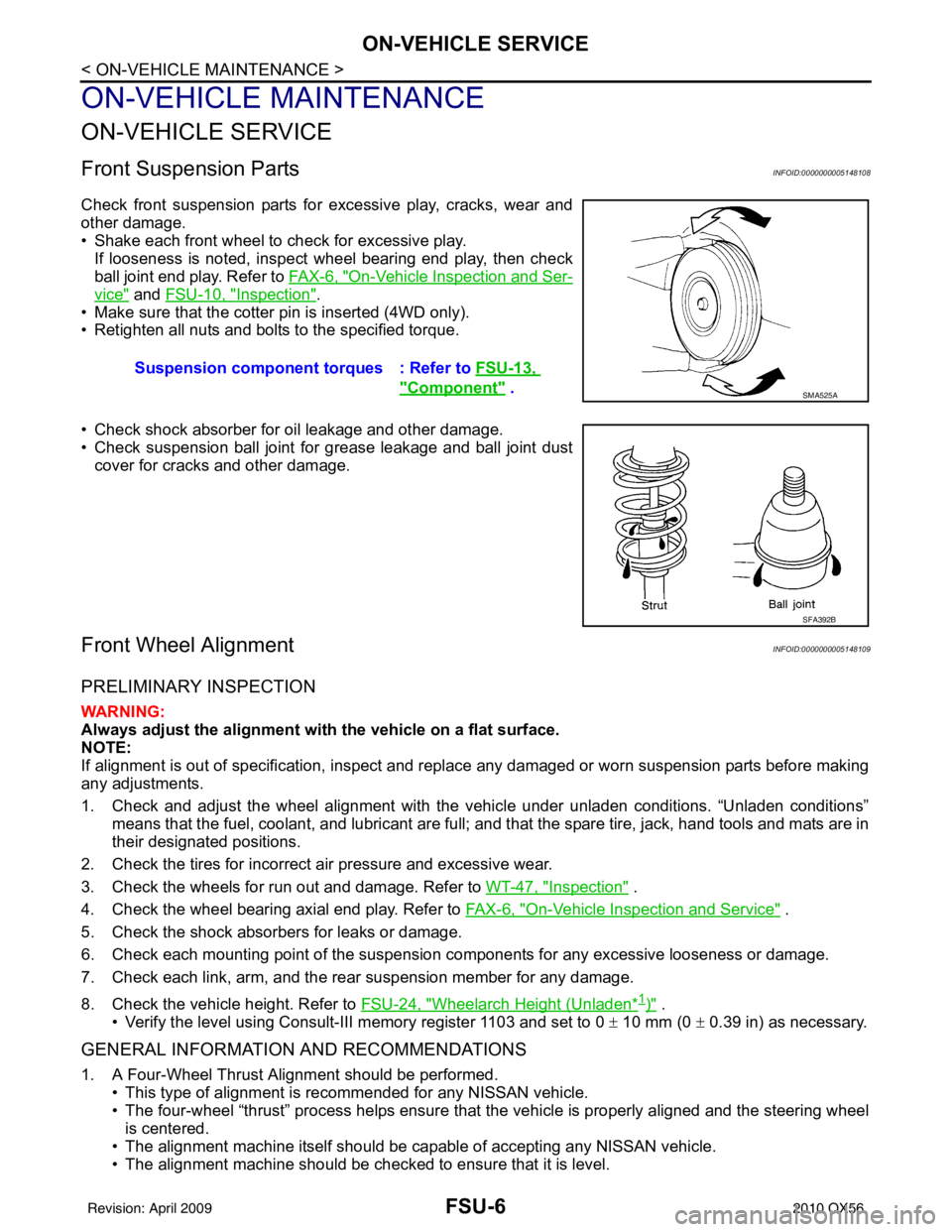
Check front suspension parts for excessive play, cracks, wear and
other damage.
• Shake each front wheel to check for excessive play.If looseness is noted, inspect wheel bearing end play, then check
ball joint end play. Refer to FA X - 6 , "
On-Vehicle Inspection and Ser-
vice" and FSU-10, "Inspection".
• Make sure that the cotter pin is inserted (4WD only).
• Retighten all nuts and bolts to the specified torque.
• Check shock absorber for oil leakage and other damage.
• Check suspension ball joint for grease leakage and ball joint dust cover for cracks and other damage.
Front Wheel AlignmentINFOID:0000000005148109
PRELIMINARY INSPECTION
WARNING:
Always adjust the alignment with the vehicle on a flat surface.
NOTE:
If alignment is out of specificat ion, inspect and replace any damaged or worn suspension parts before making
any adjustments.
1. Check and adjust the wheel alignment with the vehicle under unladen conditions. “Unladen conditions”
means that the fuel, coolant, and lubricant are full; and that the spare tire, jack, hand tools and mats are in
their designated positions.
2. Check the tires for incorrect air pressure and excessive wear.
3. Check the wheels for run out and damage. Refer to WT-47, "
Inspection" .
4. Check the wheel bearing axial end play. Refer to FA X - 6 , "
On-Vehicle Inspection and Service" .
5. Check the shock absorbers for leaks or damage.
6. Check each mounting point of the suspension components for any excessive looseness or damage.
7. Check each link, arm, and the rear suspension member for any damage.
8. Check the vehicle height. Refer to FSU-24, "
Wheelarch Height (Unladen*1)" .
• Verify the level using Consult-III memory register 1103 and set to 0 ± 10 mm (0 ± 0.39 in) as necessary.
GENERAL INFORMATION AND RECOMMENDATIONS
1. A Four-Wheel Thrust Alignment should be performed.
• This type of alignment is recommended for any NISSAN vehicle.
• The four-wheel “thrust” process helps ensure that the vehicle is properly aligned and the steering wheel
is centered.
• The alignment machine itself should be ca pable of accepting any NISSAN vehicle.
• The alignment machine should be checked to ensure that it is level. Suspension component
torques : Refer to FSU-13,
"Component" . SMA525A
SFA392B
Revision: April 20092010 QX56
Page 2224 of 4210

GI-1
GENERAL INFORMATION
C
DE
F
G H
I
J
K L
M B
GI
SECTION GI
N
O P
CONTENTS
GENERAL INFORMATION
HOW TO USE THIS MANU AL ......................3
HOW TO USE THIS MANUAL ....................... .....3
Description .......................................................... ......3
Terms ........................................................................3
Units ..........................................................................3
Contents ....................................................................3
Relation between Illustrations and Descriptions .......4
Components ..............................................................4
HOW TO FOLLOW TROUBLE DIAGNOSES .....6
Description ................................................................6
How to Follow Test Groups in Trouble Diagnosis ......6
Key to Symbols Signifying Measurements or Pro-
cedures ............................................................... ......
7
HOW TO READ WIRING DIAGRAMS ................9
Connector symbols ............................................. ......9
Sample/wiring diagram -example- ...........................10
Description ..............................................................11
ABBREVIATIONS .......................................... ....13
Abbreviation List .................................................. ....13
TIGHTENING TORQUE OF STANDARD
BOLTS ................................................................
14
Tightening Torque Table .........................................14
RECOMMENDED CHEMICAL PRODUCTS
AND SEALANTS ............................................ ....
15
Recommended Chemical Products and Sealants ....15
TERMINOLOGY .................................................16
SAE J1930 Terminology List ............................... ....16
FEATURES OF NEW MODEL .....................20
IDENTIFICATION INFORMATION .....................20
Model Variation ................................................... ....20
Identification Number ..............................................21
Identification Plate ...................................................22
Dimensions .............................................................23
Wheels & Tires .................................................... ....23
PRECAUTION ..............................................24
PRECAUTIONS .................................................24
Description ........................................................... ....24
Precaution for Supplemental Restraint System
(SRS) "AIR BAG" and "SEAT BELT PRE-TEN-
SIONER" .................................................................
24
Precaution Necessary for Steering Wheel Rota-
tion After Battery Disconnect ...................................
24
Procedures without Cowl Top Cover .......................25
General Precautions ................................................25
Three Way Catalyst .................................................27
Precaution for Fuel (Unleaded Premium Gasoline
Required) .................................................................
27
Multiport Fuel Injection System or Engine Control
System .....................................................................
27
Hoses ......................................................................27
Engine Oils ..............................................................28
Air Conditioning .......................................................29
LIFTING POINT .................................................30
Pantograph Jack ......................................................30
Garage Jack and Safety Stand ................................30
2-Pole Lift ................................................................30
TOW TRUCK TOWING .....................................32
Tow Truck Towing ...................................................32
Vehicle Recovery (Freeing a stuck vehicle) ............33
BASIC INSPECTION ...................................34
SERVICE INFORMATION FOR ELECTRICAL
INCIDENT ..........................................................
34
Work Flow ............................................................ ....34
Control Units and Electrical Parts ............................34
How to Check Terminal ...........................................35
Intermittent Incident ............................................. ....38
Circuit Inspection .....................................................41
CONSULT-III CHECKING SYSTEM .................46
Revision: April 20092010 QX56
Page 2236 of 4210

ABBREVIATIONSGI-13
< HOW TO USE THIS MANUAL >
C
DE
F
G H
I
J
K L
M B
GI
N
O PABBREVIATIONS
Abbreviation ListINFOID:0000000005149579
The following ABBREVIATIONS are used:
ABBREVIATION DESCRIPTION
A/C Air Conditioner
A/T Automatic Transaxle/Transmission
ATF Automatic Transmission Fluid
D
1Drive range 1st gear
D
2Drive range 2nd gear
D
3Drive range 3rd gear
D
4Drive range 4th gear
D5 Drive range 5th gear
FR, RR Front, Rear LH, RH Left-Hand, Right-Hand M/T Manual Transaxle/Transmission
OD Overdrive
P/S Power Steering
SAE Society of Automotive Engineers, Inc.
SDS Service Data and Specifications
SST Special Service Tools
2WD 2-Wheel Drive
4WD 4-Wheel Drive
2
22nd range 2nd gear
2
12nd range 1st gear
1
21st range 2nd gear
1
11st range 1st gear
Revision: April 20092010 QX56
Page 2244 of 4210
IDENTIFICATION INFORMATIONGI-21
< FEATURES OF NEW MODEL >
C
DE
F
G H
I
J
K L
M B
GI
N
O P
Identification NumberINFOID:0000000005149584
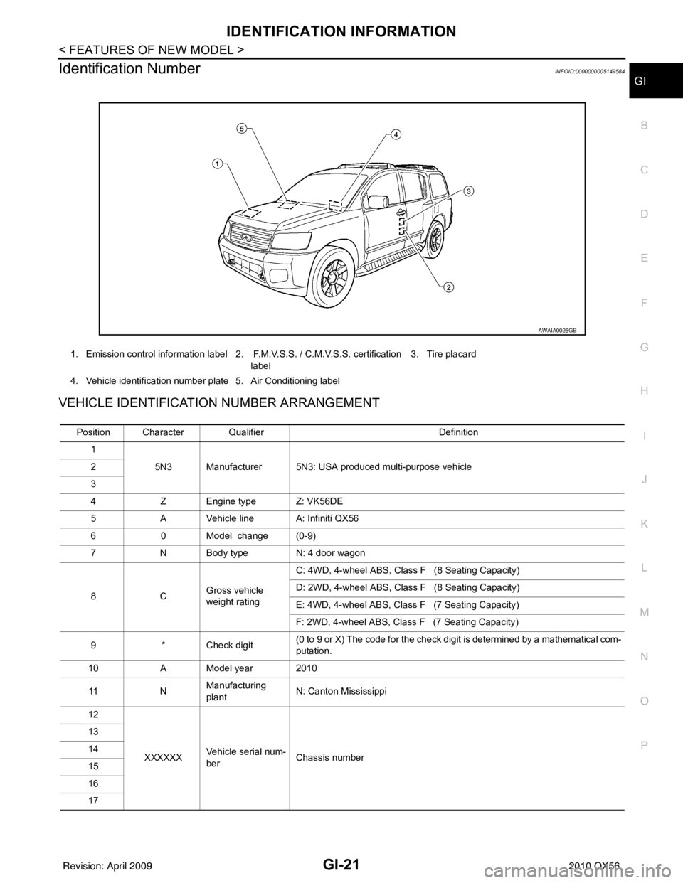
VEHICLE IDENTIFICATION NUMBER ARRANGEMENT
1. Emission control information label 2. F.M.V.S.S. / C.M.V.S.S. certification label3. Tire placard
4. Vehicle identification number plate 5. Air Conditioning label
AWAIA0026GB
Position Character Qualifier Definition
1 5N3 Manufacturer 5N3: USA produced multi-purpose vehicle
2
3
4 Z Engine type Z: VK56DE
5 A Vehicle line A: Infiniti QX56
6 0 Model change (0-9)
7 N Body type N: 4 door wagon
8C Gross vehicle
weight ratingC: 4WD, 4-wheel ABS, Class F (8 Seating Capacity)
D: 2WD, 4-wheel ABS, Class F (8 Seating Capacity)
E: 4WD, 4-wheel ABS, Class F (7 Seating Capacity)
F: 2WD, 4-wheel ABS, Class F (7 Seating Capacity)
9 * Check digit (0 to 9 or X) The code for the check digit is determined by a mathematical com-
putation.
10 A Model year 2010
11 NManufacturing
plant
N: Canton Mississippi
12
XXXXXX Vehicle serial num-
ber Chassis number
13
14
15
16
17
Revision: April 20092010 QX56
Page 2252 of 4210
PRECAUTIONSGI-29
< PRECAUTION >
C
DE
F
G H
I
J
K L
M B
GI
N
O P
Dispose of used oil and used oil filters through authorized waste disposal contractors to licensed waste dis-
posal sites, or to the waste oil reclamation trade. If in doubt, contact the local authority for advice on disposal
facilities.
It is illegal to pour used oil on to the ground, down sewers or drains, or into water sources.
The regulations concerning po llution vary between regions.
Air ConditioningINFOID:0000000005149598
Use an approved refrigerant recovery unit any time t he air conditioning system must be discharged. Refer to
HA-20, "
HFC-134a (R-134a) Service Procedure".
Revision: April 20092010 QX56
Page 2257 of 4210
GI-34
< BASIC INSPECTION >
SERVICE INFORMATION FOR ELECTRICAL INCIDENT
BASIC INSPECTION
SERVICE INFORMATION FOR ELECTRICAL INCIDENT
Work FlowINFOID:0000000005149604
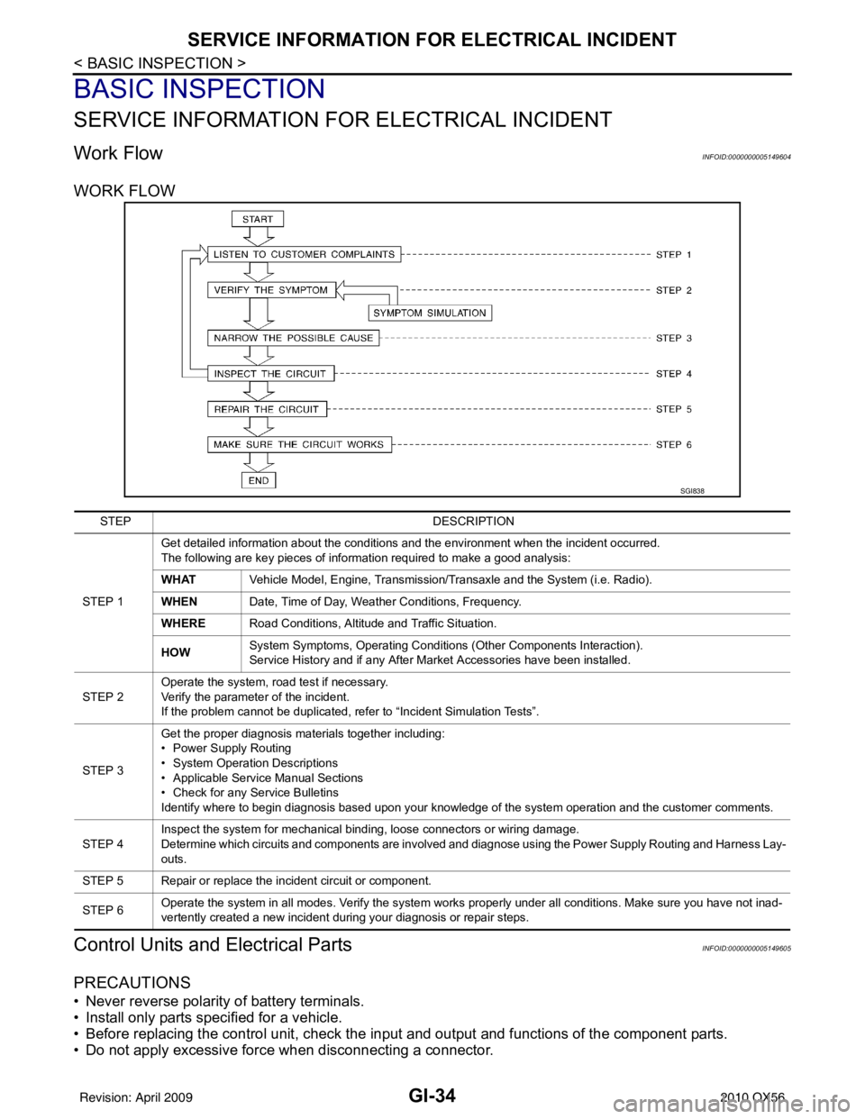
WORK FLOW
Control Units and Electrical PartsINFOID:0000000005149605
PRECAUTIONS
• Never reverse polarity of battery terminals.
• Install only parts specified for a vehicle.
• Before replacing the control unit, check the i nput and output and functions of the component parts.
• Do not apply excessive force when disconnecting a connector.
SGI838
STEP DESCRIPTION
STEP 1 Get detailed information about the conditions and the environment when the incident occurred.
The following are key pieces of information required to make a good analysis:
WHAT
Vehicle Model, Engine, Transmission/Transaxle and the System (i.e. Radio).
WHEN Date, Time of Day, Weather Conditions, Frequency.
WHERE Road Conditions, Altitude and Traffic Situation.
HOW System Symptoms, Operating Conditions
(Other Components Interaction).
Service History and if any After Market Accessories have been installed.
STEP 2 Operate the system, road test if necessary.
Verify the parameter of the incident.
If the problem cannot be duplicated, refer to “Incident Simulation Tests”.
STEP 3 Get the proper diagnosis materials together including:
• Power Supply Routing
• System Operation Descriptions
• Applicable Service Manual Sections
• Check for any Service Bulletins
Identify where to begin diagnosis based upon your knowledge of the system operation and the customer comments.
STEP 4 Inspect the system for mechanical binding, loose connectors or wiring damage.
Determine which circuits and components are involved and diagnose using the Power Supply Routing and Harness Lay-
outs.
STEP 5 Repair or replace the incident circuit or component.
STEP 6 Operate the system in all modes. Verify the system works properly under all conditions. Make sure you have not inad-
vertently created a new incident during your diagnosis or repair steps.
Revision: April 20092010 QX56
Page 2263 of 4210
GI-40
< BASIC INSPECTION >
SERVICE INFORMATION FOR ELECTRICAL INCIDENT
An unclamped or loose harness can cause wiring to be pinched by seat components (such as slide guides)
during vehicle vibration. If the wiring runs under s eating areas, inspect wire routing for possible damage or
pinching.
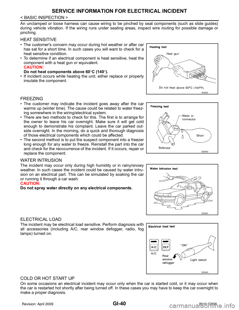
HEAT SENSITIVE
• The customer's concern may occur during hot weather or after car has sat for a short time. In such cases you will want to check for a
heat sensitive condition.
• To determine if an electrical component is heat sensitive, heat the component with a heat gun or equivalent.
CAUTION:
Do not heat components above 60 °C (140° ).
• If incident occurs while heating the unit, either replace or properly insulate the component.
FREEZING
• The customer may indicate the incident goes away after the carwarms up (winter time). The cause could be related to water freez-
ing somewhere in the wiring/electrical system.
• There are two methods to check for this. The first is to arrange for the owner to leave his car overnight. Make sure it will get cold
enough to demonstrate his complaint. Leave the car parked out-
side overnight. In the morning, do a quick and thorough diagnosis
of those electrical components which could be affected.
• The second method is to put the suspect component into a freezer long enough for any water to freeze. Reinstall the part into the car
and check for the reoccurrence of the incident. If it occurs, repair or
replace the component.
WATER INTRUSION
The incident may occur only during high humidity or in rainy/snowy
weather. In such cases the incident could be caused by water intru-
sion on an electrical part. This can be simulated by soaking the car
or running it through a car wash.
CAUTION:
Do not spray water directly on any electrical components.
ELECTRICAL LOAD
The incident may be electrical load sensitive. Perform diagnosis with
all accessories (including A/C, rear window defogger, radio, fog
lamps) turned on.
COLD OR HOT START UP
On some occasions an electrical incident may occur only when the car is started cold, or it may occur when
the car is restarted hot shortly after being turned off. In these cases you may have to keep the car overnight to
make a proper diagnosis.
SGI842
SGI843
SGI844
SGI845
Revision: April 20092010 QX56