2010 INFINITI QX56 check engine
[x] Cancel search: check enginePage 1842 of 4210
![INFINITI QX56 2010 Factory Service Manual FUEL PRESSUREEC-489
< ON-VEHICLE MAINTENANCE > [VK56DE]
C
D
E
F
G H
I
J
K L
M A
EC
NP
O
ON-VEHICLE MAINTENANCE
FUEL PRESSURE
Fuel Pressure CheckINFOID:0000000005149507
FUEL PRESSURE RELEASE
With CONS INFINITI QX56 2010 Factory Service Manual FUEL PRESSUREEC-489
< ON-VEHICLE MAINTENANCE > [VK56DE]
C
D
E
F
G H
I
J
K L
M A
EC
NP
O
ON-VEHICLE MAINTENANCE
FUEL PRESSURE
Fuel Pressure CheckINFOID:0000000005149507
FUEL PRESSURE RELEASE
With CONS](/manual-img/42/57032/w960_57032-1841.png)
FUEL PRESSUREEC-489
< ON-VEHICLE MAINTENANCE > [VK56DE]
C
D
E
F
G H
I
J
K L
M A
EC
NP
O
ON-VEHICLE MAINTENANCE
FUEL PRESSURE
Fuel Pressure CheckINFOID:0000000005149507
FUEL PRESSURE RELEASE
With CONSULT-IIl
1. Turn ignition switch ON.
2. Perform “FUEL PRESSURE RELEASE” in
“WORK SUPPORT” mode with CONSULT-IIl.
3. Start engine.
4. After engine stalls, crank it two or three times to release all fuel pressure.
5. Turn ignition switch OFF.
Without CONSULT-IIl
1. Remove fuel pump fuse located in IPDM E/R.
2. Start engine.
3. After engine stalls, crank it two or three times to release all fuel pressure.
4. Turn ignition switch OFF.
5. Reinstall fuel pump fuse after servicing fuel system.
FUEL PRESSURE CHECK
CAUTION:
• Before disconnecting fuel line, release fuel pressure from fuel line to eliminate danger.
• Be careful not to scratch or get the fuel hose connection area dirty when servicing, so that the quick connector o-ring maintains sealability.
• Use Fuel Pressure Gauge Kit J-44321 and Fuel Pr essure Adapter J-44321-6 to check fuel pressure.
• Do not perform fuel pressure check with electrical system operating (i.e. lights, rear defog, A/C, etc.).
Fuel pressure gauge may indicate false readings du e to varying engine loads and changes in mani-
fold vacuum.
NOTE:
Prepare pans or saucers under the disconnected fuel line because the fuel may spill out. The fuel pres-
sure cannot be completely released because JA60 models do not have fuel return system.
1. Release fuel pressure to zero. Refer to "FUEL PRESSURE RELEASE".
2. Remove engine cover.
3. Remove fuel hose using Quick Connector Release J-45488. Refer to EM-26
.
• Do not twist or kink fuel hose because it is plastic hose.
• Do not remove fuel hose from quick connector.
• Keep fuel hose connections clean.
4. Install Fuel Pressure Adapter J-44321-6 and Fuel Pressure Gauge (from kit J-44321) as shown in figure.
• Do not distort or bend fuel rail tube when installing fuel pres-sure gauge adapter.
• When reconnecting fuel hose, che ck the original fuel hose for
damage and abnormality.
5. Turn ignition switch ON (reactivate fuel pump), and check for fuel leakage.
6. Start engine and check for fuel leakage.
7. Read the indication of fuel pressure gauge. • During fuel pressure check, check for fuel leakage from fuel
connection every 3 minutes.
BBIA0380E
BBIA0390E
Revision: April 20092010 QX56
Page 1844 of 4210
![INFINITI QX56 2010 Factory Service Manual EVAP LEAK CHECKEC-491
< ON-VEHICLE MAINTENANCE > [VK56DE]
C
D
E
F
G H
I
J
K L
M A
EC
NP
O
EVAP LEAK CHECK
How to Detect Fuel Vapor LeakageINFOID:0000000005149508
CAUTION:
• Never use compressed air INFINITI QX56 2010 Factory Service Manual EVAP LEAK CHECKEC-491
< ON-VEHICLE MAINTENANCE > [VK56DE]
C
D
E
F
G H
I
J
K L
M A
EC
NP
O
EVAP LEAK CHECK
How to Detect Fuel Vapor LeakageINFOID:0000000005149508
CAUTION:
• Never use compressed air](/manual-img/42/57032/w960_57032-1843.png)
EVAP LEAK CHECKEC-491
< ON-VEHICLE MAINTENANCE > [VK56DE]
C
D
E
F
G H
I
J
K L
M A
EC
NP
O
EVAP LEAK CHECK
How to Detect Fuel Vapor LeakageINFOID:0000000005149508
CAUTION:
• Never use compressed air
or a high pressure pump.
• Do not exceed 4.12 kPa (0.042 kg/cm
2, 0.6 psi) of pressure in EVAP system.
NOTE:
• Do not start engine.
• Improper installation of EVAP service port adapter to the EVAP service port may cause a leak.
WITH CONSULT-IIl
1. Attach the EVAP service port adapter securely to the EVAP service port.
2. Also attach the pressure pump and hose to the EVAP service port adapter.
3. Turn ignition switch ON.
4. Select the “EVAP SYSTEM CLOSE” of “WORK SUPPORT MODE” with CONSULT-IIl.
5. Touch “START”. A bar graph (Pressure indicating display) will appear on the screen.
6. Apply positive pressure to the EVAP system until the pressure indicator reaches the middle of the bar graph.
7. Remove EVAP service port adapter and hose with pressure pump.
8. Locate the leak using a leak detector. Refer to EC-37, "
Descrip-
tion".
WITHOUT CONSULT-IIl
1. Attach the EVAP service port adapter securely to the EVAP ser-
vice port.
2. Also attach the pressure pump with pressure gauge to the EVAP service port adapter.
SEF200U
BBIA0366E
SEF462UA
Revision: April 20092010 QX56
Page 1852 of 4210
EM-1
ENGINE
C
DE
F
G H
I
J
K L
M
SECTION EM
A
EM
N
O P
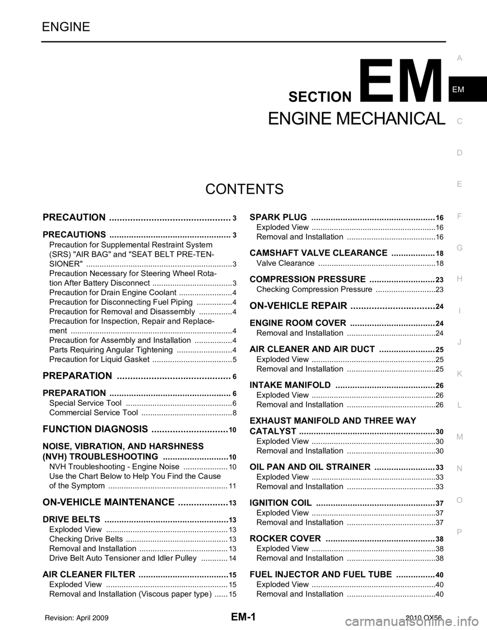
CONTENTS
ENGINE MECHANICAL
PRECAUTION ....... ........................................3
PRECAUTIONS .............................................. .....3
Precaution for Supplemental Restraint System
(SRS) "AIR BAG" and "SEAT BELT PRE-TEN-
SIONER" ............................................................. ......
3
Precaution Necessary for Steering Wheel Rota-
tion After Battery Disconnect ............................... ......
3
Precaution for Drain Engine Coolant .........................4
Precaution for Disconnecting Fuel Piping .................4
Precaution for Removal and Disassembly ................4
Precaution for Inspection, Repair and Replace-
ment .................................................................... ......
4
Precaution for Assembly and Installation ..................4
Parts Requiring Angular Tightening ..........................4
Precaution for Liquid Gasket ............................... ......5
PREPARATION ............................................6
PREPARATION .............................................. .....6
Special Service Tool ........................................... ......6
Commercial Service Tool ..........................................8
FUNCTION DIAGNOSIS ..............................10
NOISE, VIBRATION, AND HARSHNESS
(NVH) TROUBLESHOOTING ........................ ....
10
NVH Troubleshooting - Engine Noise ................. ....10
Use the Chart Below to Help You Find the Cause
of the Symptom .......................................................
11
ON-VEHICLE MAINTENANCE ....................13
DRIVE BELTS ................................................ ....13
Exploded View .................................................... ....13
Checking Drive Belts ...............................................13
Removal and Installation .........................................13
Drive Belt Auto Tensioner and Idler Pulley ......... ....14
AIR CLEANER FILTER ......................................15
Exploded View .................................................... ....15
Removal and Installation (Viscous paper type) .......15
SPARK PLUG ...................................................16
Exploded View ..................................................... ....16
Removal and Installation .........................................16
CAMSHAFT VALVE CLEARANCE ..................18
Valve Clearance ......................................................18
COMPRESSION PRESSURE ...........................23
Checking Compression Pressure ............................23
ON-VEHICLE REPAIR .................................24
ENGINE ROOM COVER ...................................24
Removal and Installation ..................................... ....24
AIR CLEANER AND AIR DUCT .......................25
Exploded View .........................................................25
Removal and Installation .........................................25
INTAKE MANIFOLD .........................................26
Exploded View .........................................................26
Removal and Installation .........................................26
EXHAUST MANIFOLD AND THREE WAY
CATALYST ........................................................
30
Exploded View .........................................................30
Removal and Installation .........................................30
OIL PAN AND OIL STRAINER .........................33
Exploded View .........................................................33
Removal and Installation .........................................33
IGNITION COIL .................................................37
Exploded View .........................................................37
Removal and Installation .........................................37
ROCKER COVER .............................................38
Exploded View .........................................................38
Removal and Installation .........................................38
FUEL INJECTOR AND FUEL TUBE ................40
Exploded View .........................................................40
Removal and Installation .........................................40
Revision: April 20092010 QX56
Page 1855 of 4210
EM-4
< PRECAUTION >
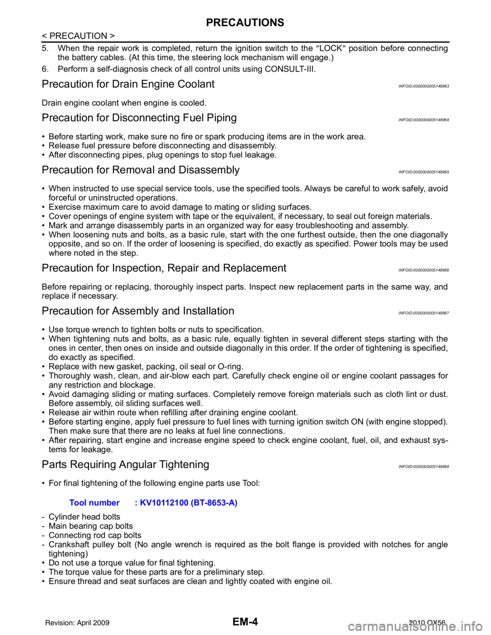
PRECAUTIONS
5. When the repair work is completed, return the ignition switch to the ″LOCK ″ position before connecting
the battery cables. (At this time, the steering lock mechanism will engage.)
6. Perform a self-diagnosis check of a ll control units using CONSULT-III.
Precaution for Drain Engine CoolantINFOID:0000000005148963
Drain engine coolant when engine is cooled.
Precaution for Disconnecting Fuel PipingINFOID:0000000005148964
• Before starting work, make sure no fire or spark producing items are in the work area.
• Release fuel pressure before disconnecting and disassembly.
• After disconnecting pipes, plug openings to stop fuel leakage.
Precaution for Removal and DisassemblyINFOID:0000000005148965
• When instructed to use special service tools, use the s pecified tools. Always be careful to work safely, avoid
forceful or uninstructed operations.
• Exercise maximum care to avoid damage to mating or sliding surfaces.
• Cover openings of engine system with tape or the equivalent, if necessary, to seal out foreign materials.
• Mark and arrange disassembly parts in an organi zed way for easy troubleshooting and assembly.
• When loosening nuts and bolts, as a basic rule, start with the one furthest outside, then the one diagonally opposite, and so on. If the order of loosening is specified, do exactly as specified. Power tools may be used
where noted in the step.
Precaution for Inspection, Repair and ReplacementINFOID:0000000005148966
Before repairing or replacing, thoroughly inspect parts. Inspect new replacement parts in the same way, and
replace if necessary.
Precaution for Assembly and InstallationINFOID:0000000005148967
• Use torque wrench to tighten bolts or nuts to specification.
• When tightening nuts and bolts, as a basic rule, equally tighten in several different steps starting with theones in center, then ones on inside and outside diagonally in this order. If the order of tightening is specified,
do exactly as specified.
• Replace with new gasket, packing, oil seal or O-ring.
• Thoroughly wash, clean, and air-blow each part. Carefully check engine oil or engine coolant passages for any restriction and blockage.
• Avoid damaging sliding or mating surfaces. Completely remove foreign materials such as cloth lint or dust. Before assembly, oil sliding surfaces well.
• Release air within route when refilling after draining engine coolant.
• Before starting engine, apply fuel pressure to fuel lines with turning ignition switch ON (with engine stopped). Then make sure that there are no leaks at fuel line connections.
• After repairing, start engine and increase engine s peed to check engine coolant, fuel, oil, and exhaust sys-
tems for leakage.
Parts Requiring Angular TighteningINFOID:0000000005148968
• For final tightening of the following engine parts use Tool:
- Cylinder head bolts
- Main bearing cap bolts
- Connecting rod cap bolts
- Crankshaft pulley bolt (No angle wrench is required as the bolt flange is provided with notches for angle tightening)
• Do not use a torque value for final tightening.
• The torque value for these parts are for a preliminary step.
• Ensure thread and seat surfaces are clean and lightly coated with engine oil. Tool number : KV10112100 (BT-8653-A)
Revision: April 20092010 QX56
Page 1862 of 4210
NOISE, VIBRATION, AND HARSHNESS (NVH) TROUBLESHOOTINGEM-11
< FUNCTION DIAGNOSIS >
C
DE
F
G H
I
J
K L
M A
EM
NP
O
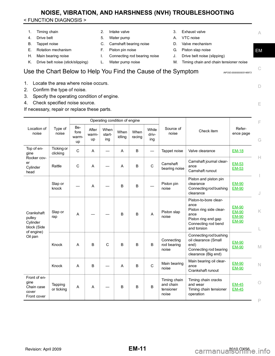
Use the Chart Below to Help You
Find the Cause of the SymptomINFOID:0000000005148973
1. Locate the area where noise occurs.
2. Confirm the type of noise.
3. Specify the operating condition of engine.
4. Check specified noise source.
If necessary, repair or replace these parts.
1. Timing chain 2. Intake valve3. Exhaust valve
4. Drive belt 5. Water pumpA. VTC noise
B. Tappet noise C. Camshaft bearing noiseD. Valve mechanism
E. Rotation mechanism F. Piston pin noise G. Piston slap noise
H. Main bearing noise I. Connecting rod bearing noise J. Drive belt noise (slipping)
K. Drive belt noise (stick/slipping) L. Water pump noise M. Timing chain and chain tensioner noise
Location of noise Ty p e o f
noise Operating condition of engine
Source of noise Check item Refer-
ence page
Be-
fore
warm-
up After
warm- up When
start- ing When
idling When
racing While
driv- ing
Top of en-
gine
Rocker cov-
er
Cylinder
head Ticking or
clicking
C A — A B — Tappet noise Valve clearance
EM-18
Rattle C A — A B CCamshaft
bearing noiseCamshaft journal clear-
ance
Camshaft runout EM-53EM-53
Crankshaft
pulley
Cylinder
block (Side
of engine)
Oil panSlap or
knock
—A—B B—
Piston pin
noisePiston and piston pin
clearance
Connecting rod bushing
clearance
EM-90
EM-90
Slap or
rap
A——B B A
Piston slap
noisePiston-to-bore clear-
ance
Piston ring side clear-
ance
Piston ring end gap
Connecting rod bend
and torsion EM-90EM-90
EM-90
EM-90
Knock A B C B B B
Connecting
rod bearing
noiseConnecting rod bushing
oil clearance (Small
end)
Connecting rod bearing
clearance (Big end)
EM-90EM-90
Knock A B — A B C
Main bearing
noiseMain bearing oil clear-
ance
Crankshaft runout EM-90EM-90
Front of en-
gine
Chain case
cover
Front coverTapping
or ticking
AA—BBB Timing chain
and chain
tensioner
noiseTiming chain cracks
and wear
Timing chain tensioner
operation
EM-45
EM-45
Revision: April 20092010 QX56
Page 1863 of 4210
EM-12
< FUNCTION DIAGNOSIS >
NOISE, VIBRATION, AND HARSHNESS (NVH) TROUBLESHOOTING
A: Closely related B: Related C: Sometimes related —: Not relatedFront of en-
gine
Squeak-
ing or
fizzing
AB—B—C
Drive belts
(Sticking or
slipping)Drive belts deflection
EM-13
Creaking A B A B A B Drive belts
(Slipping)Idler pulley bearing op-
eration
Squall
Creaking AB—BAB Water pump
noiseWater pump operation
CO-20
Rattle — — A — — — VTC VTC lock pin clearanceEM-62
Location of
noise Type of
noise Operating condition of engine
Source of noise Check item Refer-
ence page
Be-
fore
warm- up After
warm- up When
start- ing When
idling When
racing While
driv- ing
Revision: April 20092010 QX56
Page 1864 of 4210
DRIVE BELTSEM-13
< ON-VEHICLE MAINTENANCE >
C
DE
F
G H
I
J
K L
M A
EM
NP
O
ON-VEHICLE MAINTENANCE
DRIVE BELTS
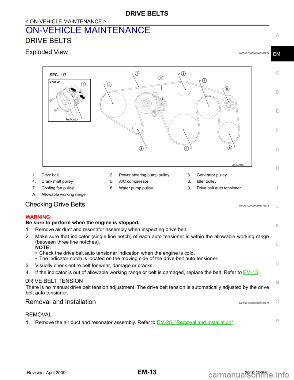
Exploded ViewINFOID:0000000005148974
Checking Drive BeltsINFOID:0000000005148975
WARNING:
Be sure to perform when the engine is stopped.
1. Remove air duct and resonator assembly when inspecting drive belt.
2. Make sure that indicator (single line notch) of eac
h auto tensioner is within the allowable working range
(between three line notches).
NOTE:
• Check the drive belt auto tensioner indication when the engine is cold.
• The indicator notch is located on the moving side of the drive belt auto tensioner.
3. Visually check entire belt for wear, damage or cracks.
4. If the indicator is out of allowable working range or belt is damaged, replace the belt. Refer to EM-13
.
DRIVE BELT TENSION
There is no manual drive belt tension adjustment. The driv e belt tension is automatically adjusted by the drive
belt auto tensioner.
Removal and InstallationINFOID:0000000005148976
REMOVAL
1. Remove the air duct and resonator assembly. Refer to EM-25, "Removal and Installation".
1. Drive belt2. Power steering pump pulley 3. Generator pulley
4. Crankshaft pulley 5. A/C compressor6. Idler pulley
7. Cooling fan pulley 8. Water pump pulley9. Drive belt auto tensioner
A. Allowable working range
LBIA0391E
Revision: April 20092010 QX56
Page 1873 of 4210
EM-22
< ON-VEHICLE MAINTENANCE >
CAMSHAFT VALVE CLEARANCE
6. Install the camshaft.
7. Manually turn the crankshaft pulley a few turns.
8. Make sure the valve clearances for a cold engine are within specifications. Refer to EM-108, "
Standard
and Limit".
9. After completing the repair, check the valve clearanc es again with the specifications for a warmed engine.
Make sure the values are wit hin specifications. Refer to EM-108, "
Standard and Limit".
Revision: April 20092010 QX56