2010 INFINITI QX56 steering
[x] Cancel search: steeringPage 1970 of 4210

EX-1
ENGINE
C
DE
F
G H
I
J
K L
M
SECTION EX
A
EX
N
O P
CONTENTS
EXHAUST SYSTEM
PRECAUTION ....... ........................................2
PRECAUTIONS .............................................. .....2
Precaution for Supplemental Restraint System
(SRS) "AIR BAG" and "SEAT BELT PRE-TEN-
SIONER" ............................................................. ......
2
Precaution Necessary for Steering Wheel Rota-
tion After Battery Disconnect ............................... ......
2
PREPARATION ............................................4
PREPARATION .............................................. .....4
Special Service Tool ........................................... ......4
Commercial Service Tool .................................... .....4
ON-VEHICLE MAINTENANCE .....................5
EXHAUST SYSTEM ...........................................5
Checking Exhaust System ................................... .....5
ON-VEHICLE REPAIR ..................................6
EXHAUST SYSTEM ...........................................6
Exploded View ..................................................... .....6
Removal and Installation ..........................................6
Revision: April 20092010 QX56
Page 1971 of 4210

EX-2
< PRECAUTION >
PRECAUTIONS
PRECAUTION
PRECAUTIONS
Precaution for Supplemental Restraint System (SRS) "AIR BAG" and "SEAT BELT
PRE-TENSIONER"
INFOID:0000000005260138
The Supplemental Restraint System such as “A IR BAG” and “SEAT BELT PRE-TENSIONER”, used along
with a front seat belt, helps to reduce the risk or severity of injury to the driver and front passenger for certain
types of collision. This system includes seat belt switch inputs and dual stage front air bag modules. The SRS
system uses the seat belt switches to determine the front air bag deployment, and may only deploy one front
air bag, depending on the severity of a collision and w hether the front occupants are belted or unbelted.
Information necessary to service the system safely is included in the SR and SB section of this Service Man-
ual.
WARNING:
• To avoid rendering the SRS inopera tive, which could increase the risk of personal injury or death in
the event of a collision which would result in air bag inflation, all maintenance must be performed by
an authorized NISSAN/INFINITI dealer.
• Improper maintenance, including in correct removal and installation of the SRS, can lead to personal
injury caused by unintent ional activation of the system. For re moval of Spiral Cable and Air Bag
Module, see the SR section.
• Do not use electrical test equipmen t on any circuit related to the SRS unless instructed to in this
Service Manual. SRS wiring harn esses can be identified by yellow and/or orange harnesses or har-
ness connectors.
PRECAUTIONS WHEN USING POWER TOOLS (AIR OR ELECTRIC) AND HAMMERS
WARNING:
• When working near the Airbag Diagnosis Sensor Unit or other Airbag System sensors with the Igni-
tion ON or engine running, DO NOT use air or electri c power tools or strike near the sensor(s) with a
hammer. Heavy vibration could activate the sensor( s) and deploy the air bag(s), possibly causing
serious injury.
• When using air or electric power tools or hammers , always switch the Ignition OFF, disconnect the
battery, and wait at least 3 minu tes before performing any service.
Precaution Necessary for Steering W heel Rotation After Battery Disconnect
INFOID:0000000005260139
NOTE:
• This Procedure is applied only to models with Intelligent Key system and NATS (NISSAN ANTI-THEFT SYS-
TEM).
• Remove and install all control units after disconnecting both battery cables with the ignition knob in the
″LOCK ″ position.
• Always use CONSULT-III to perform self-diagnosis as a part of each function inspection after finishing work.
If DTC is detected, perform trouble diagnosis according to self-diagnostic results.
For models equipped with the Intelligent Key system and NATS, an electrically controlled steering lock mech-
anism is adopted on the key cylinder.
For this reason, if the battery is disconnected or if the battery is discharged, the steering wheel will lock and
steering wheel rotation will become impossible.
If steering wheel rotation is required when battery pow er is interrupted, follow the procedure below before
starting the repair operation.
OPERATION PROCEDURE
1. Connect both battery cables. NOTE:
Supply power using jumper cables if battery is discharged.
2. Use the Intelligent Key or mechanical key to turn the ignition switch to the ″ACC ″ position. At this time, the
steering lock will be released.
3. Disconnect both battery cables. The steering lock will remain released and the steering wheel can be rotated.
4. Perform the necessary repair operation.
Revision: April 20092010 QX56
Page 1972 of 4210

PRECAUTIONSEX-3
< PRECAUTION >
C
DE
F
G H
I
J
K L
M A
EX
NP
O
5. When the repair work is completed, return the ignition switch to the
″LOCK ″ position before connecting
the battery cables. (At this time, the steering lock mechanism will engage.)
6. Perform a self-diagnosis check of al l control units using CONSULT-III.
Revision: April 20092010 QX56
Page 1979 of 4210

EXL-3
C
DE
F
G H
I
J
K
M A
B
EXL
N
O P
PRECAUTION ....... .....................................143
PRECAUTIONS .............................................. ..143
Precaution for Supplemental Restraint System
(SRS) "AIR BAG" and "SEAT BELT PRE-TEN-
SIONER" ............................................................. ..
143
Precaution Necessary for Steering Wheel Rota-
tion After Battery Disconnect ............................... ..
143
General precautions for service operations ..........144
ON-VEHICLE REPAIR .... ...........................145
ADJUSTMENT AND INSPECTION ................ ..145
HEADLAMP ........................................................... ..145
HEADLAMP : Aiming Adjustment .........................145
FRONT FOG LAMP ............................................... ..146
FRONT FOG LAMP : Aiming Adjustment .............146
REMOVAL AND INSTALLATION .............148
HEADLAMP .................................................... ..148
Bulb Replacement .................................................148
Removal and Installation .......................................149
Disassembly and Assembly ................................ ..149
AUTO LIGHT SYSTEM ....................................151
Removal and Installation .......................................151
FRONT FOG LAMP ........................................152
Bulb Replacement ............................................... ..152
Removal and Installation .......................................152
LIGHTING & TURN SIGNAL SWITCH ...........154
Removal and Installation .......................................154
HAZARD SWITCH ..........................................155
Removal and Installation .......................................155
LICENSE PLATE LAMP .................................156
Bulb Replacement .................................................156
Removal and Installation .......................................156
STOP LAMP ....................................................157
Bulb Replacement .................................................157
Removal and Installation .......................................157
REAR COMBINATION LAMP .........................158
Bulb Replacement .................................................158
Removal and Installation .......................................158
SERVICE DATA AND SPECIFICATIONS
(SDS) ............... .......................................... .
159
BULB SPECIFICATIONS ................................159
Headlamp ............................................................ ..159
Exterior Lamp ........................................................159
Revision: April 20092010 QX56
Page 2119 of 4210

PRECAUTIONSEXL-143
< PRECAUTION >
C
DE
F
G H
I
J
K
M A
B
EXL
N
O P
PRECAUTION
PRECAUTIONS
Precaution for Supplemental Restraint System (SRS) "AIR BAG" and "SEAT BELT
PRE-TENSIONER"
INFOID:0000000005369809
The Supplemental Restraint System such as “AIR BAG” and “SEAT BELT PRE-TENSIONER”, used along
with a front seat belt, helps to reduce the risk or severi ty of injury to the driver and front passenger for certain
types of collision. This system includes seat belt switch inputs and dual stage front air bag modules. The SRS
system uses the seat belt switches to determine the front air bag deployment, and may only deploy one front
air bag, depending on the severity of a collision and w hether the front occupants are belted or unbelted.
Information necessary to service the system safely is included in the SR and SB section of this Service Man-
ual.
WARNING:
• To avoid rendering the SRS inoper ative, which could increase the risk of personal injury or death in
the event of a collision which would result in air bag inflation, all maintenance must be performed by
an authorized NISSAN/INFINITI dealer.
• Improper maintenance, including in correct removal and installation of the SRS, can lead to personal
injury caused by unintentional act ivation of the system. For removal of Spiral Cable and Air Bag
Module, see the SR section.
• Do not use electrical test equipm ent on any circuit related to the SRS unless instructed to in this
Service Manual. SRS wiring harnesses can be identi fied by yellow and/or orange harnesses or har-
ness connectors.
PRECAUTIONS WHEN USING POWER TOOLS (AIR OR ELECTRIC) AND HAMMERS
WARNING:
• When working near the Airbag Diagnosis Sensor Un it or other Airbag System sensors with the Igni-
tion ON or engine running, DO NOT use air or el ectric power tools or strike near the sensor(s) with a
hammer. Heavy vibration could activate the sensor( s) and deploy the air bag(s), possibly causing
serious injury.
• When using air or electric power tools or hammers, always switch the Ignition OFF, disconnect the battery, and wait at least 3 minutes before performing any service.
Precaution Necessary for Steering Wheel Rotation After Battery Disconnect
INFOID:0000000005369810
NOTE:
• Before removing and installing any control units, first tu rn the push-button ignition switch to the LOCK posi-
tion, then disconnect both battery cables.
• After finishing work, confirm that all control unit connectors are connected properly, then re-connect both
battery cables.
• Always use CONSULT-III to perform self-diagnosis as a part of each function inspection after finishing work.
If a DTC is detected, perform trouble diagnos is according to self-diagnosis results.
This vehicle is equipped with a push-button ignition switch and a steering lock unit.
If the battery is disconnect ed or discharged, the steering wheel will lock and cannot be turned.
If turning the steering wheel is required with the battery disconnected or discharged, follow the procedure
below before starting the repair operation.
OPERATION PROCEDURE
1. Connect both battery cables.
NOTE:
Supply power using jumper cables if battery is discharged.
2. Carry the Intelligent Key or insert it to the key slot and turn the push-button ignition switch to ACC position. (At this time, the steering lock will be released.)
3. Disconnect both battery cables. The steering lock will remain released with both battery cables discon- nected and the steering wheel can be turned.
4. Perform the necessary repair operation.
Revision: April 20092010 QX56
Page 2120 of 4210

EXL-144
< PRECAUTION >
PRECAUTIONS
5. When the repair work is completed, re-connect both battery cables. With the brake pedal released, turn
the push-button ignition switch from ACC position to ON position, then to LOCK position. (The steering
wheel will lock when the push-button igniti on switch is turned to LOCK position.)
6. Perform self-diagnosis check of all control units using CONSULT-III.
General precautions for service operationsINFOID:0000000005369811
• When removing or disassembling any part, be careful not to damage or deform it. Protect parts which may
get in the way with cloth.
• When removing parts with a screw driver or other tool , protect parts by wrapping them with vinyl or tape.
• Keep removed parts protected with cloth.
• If an non-reuseable part is removed, replace it with a new one.
• After re-assembly has been completed, make sure each part functions correctly.
• Never work with wet hands.
• Turn the combination switch (lighting and turn signal switch) OFF before disconnecting and connecting the connector.
• Do not use organic solvent (paint thinner or gasoline) to clean lamps or remove sealant residue.
Revision: April 20092010 QX56
Page 2130 of 4210

EXL-154
< REMOVAL AND INSTALLATION >
LIGHTING & TURN SIGNAL SWITCH
LIGHTING & TURN SIGNAL SWITCH
Removal and InstallationINFOID:0000000005146704
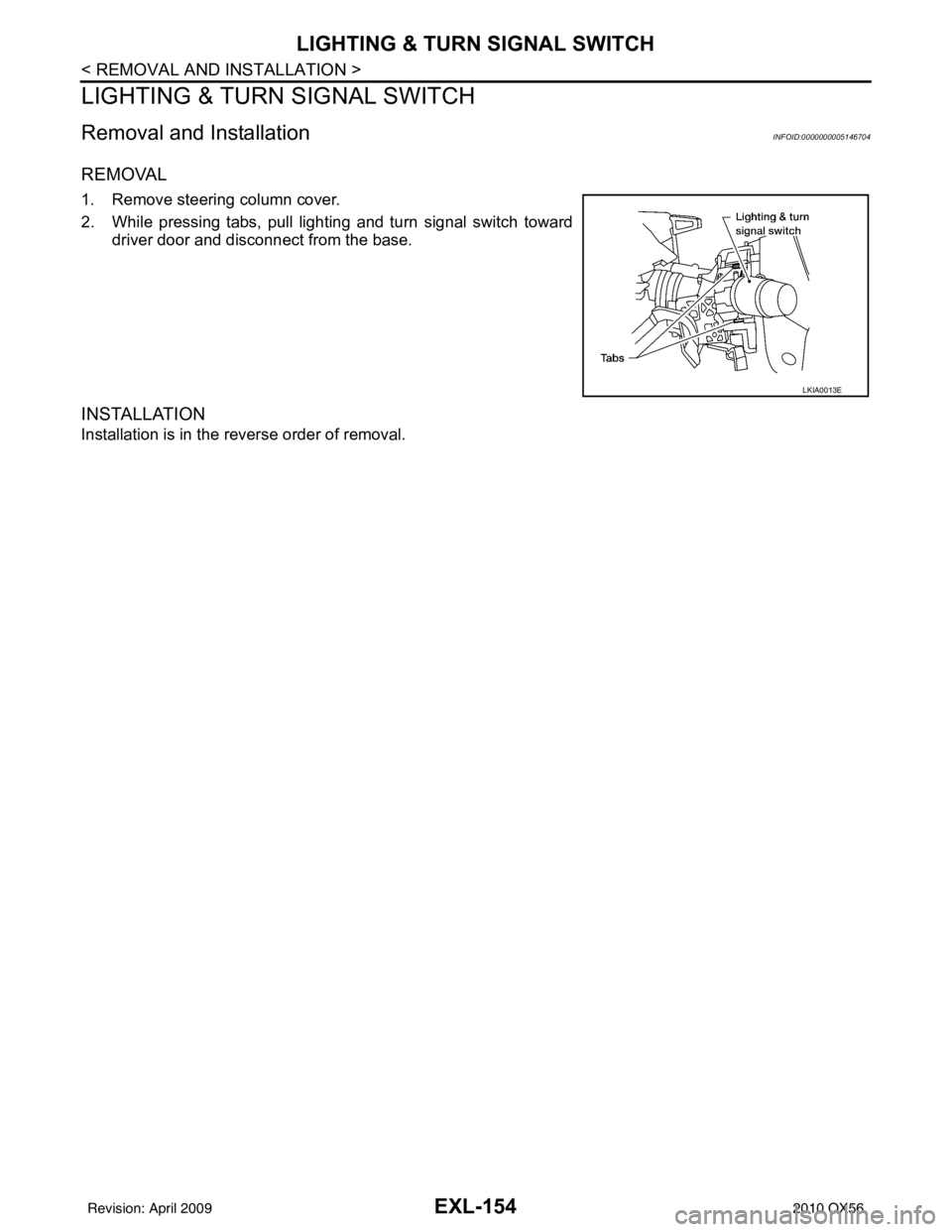
REMOVAL
1. Remove steering column cover.
2. While pressing tabs, pull lighting and turn signal switch toward
driver door and disconnect from the base.
INSTALLATION
Installation is in the reverse order of removal.
LKIA0013E
Revision: April 20092010 QX56
Page 2136 of 4210

EXT-1
BODY EXTERIOR, DOORS, ROOF & VEHICLE SECURITY
C
DE
F
G H
I
J
L
M
SECTION EXT
A
B
EXT
N
O P
CONTENTS
EXTERIOR
SERVICE INFORMATION .. ..........................2
PRECAUTIONS .............................................. .....2
Precaution for Supplemental Restraint System
(SRS) "AIR BAG" and "SEAT BELT PRE-TEN-
SIONER" ............................................................. ......
2
Precaution Necessary for Steering Wheel Rota-
tion After Battery Disconnect ............................... ......
2
Service Notice ...........................................................3
PREPARATION ...................................................4
Special Service Tool ........................................... ......4
Commercial Service Tool ..........................................4
SQUEAK AND RATTLE TROUBLE DIAG-
NOSES ................................................................
5
Work Flow ........................................................... ......5
Generic Squeak and Rattle Troubleshooting ............7
Diagnostic Worksheet ...............................................9
CLIP AND FASTENER .......................................11
Description .......................................................... ....11
FRONT BUMPER ...............................................13
Removal and Installation .........................................13
REAR BUMPER ............................................. ....15
Removal and Installation .........................................15
FRONT GRILLE .................................................17
Removal and Installation ..................................... ....17
COWL TOP .......................................................18
Removal and Installation .........................................18
FRONT FENDER ...............................................20
Removal and Installation .........................................20
OVER FENDER .................................................21
Removal and Installation .........................................21
FENDER PROTECTOR ....................................23
Removal and Installation .........................................23
LICENSE LAMP FINISHER ..............................24
Removal and Installation .........................................24
RUNNING BOARDS .........................................25
Removal and Installation .........................................25
REAR SPOILER ................................................26
Removal and Installation .........................................26
ROOF RACK .....................................................27
Removal and Installation ..................................... ....27
DOOR OUTSIDE MOLDING .............................28
Removal and Installation .........................................28
SIDE GUARD MOLDING ..................................30
Removal and Installation ..................................... ....30
Revision: April 20092010 QX56