2010 INFINITI QX56 Air
[x] Cancel search: AirPage 3995 of 4210
DUCTS AND GRILLESVTL-33
< ON-VEHICLE REPAIR >
C
DE
F
G H
J
K L
M A
B
VTL
N
O P
DUCTS AND GRILLES
ComponentINFOID:0000000005147624
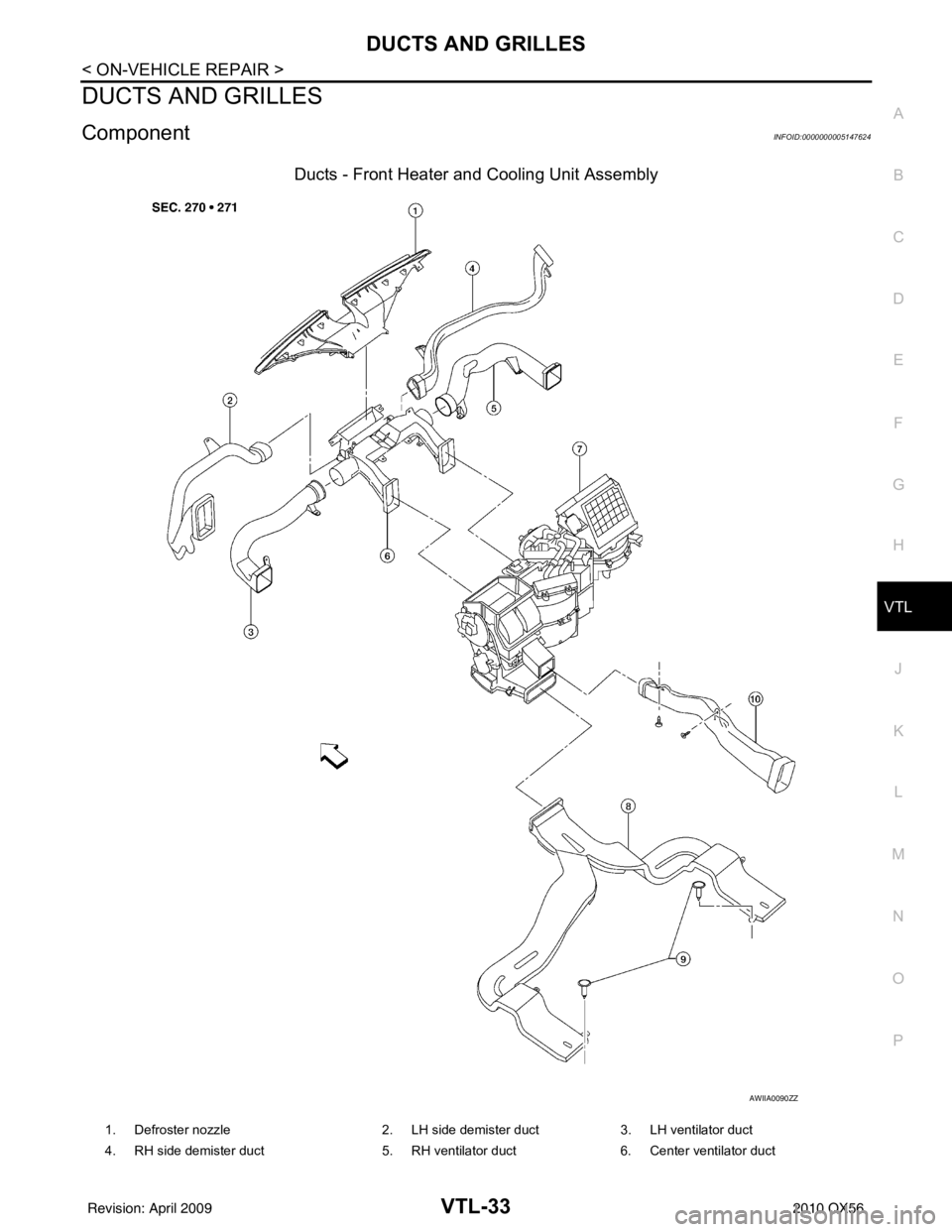
Ducts - Front Heater and Cooling Unit Assembly
AWIIA0090ZZ
1. Defroster nozzle 2. LH side demister duct3. LH ventilator duct
4. RH side demister duct 5. RH ventilator duct6. Center ventilator duct
Revision: April 20092010 QX56
Page 3996 of 4210
VTL-34
< ON-VEHICLE REPAIR >
DUCTS AND GRILLES
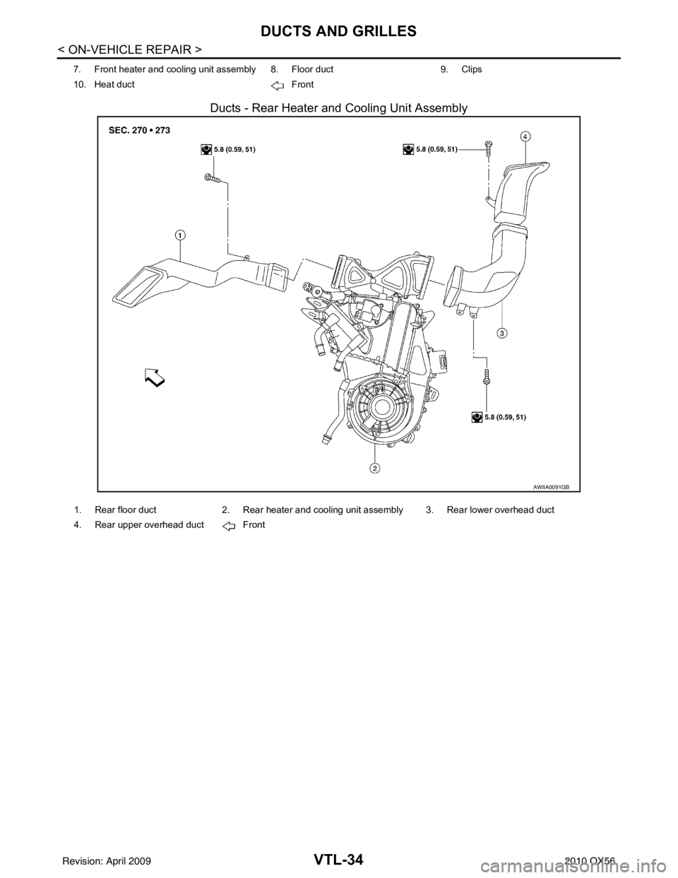
Ducts - Rear Heater and Cooling Unit Assembly
7. Front heater and cooling unit assembly 8. Floor duct9. Clips
10. Heat duct Front
AWIIA0091GB
1. Rear floor duct2. Rear heater and cooling unit assembly 3. Rear lower overhead duct
4. Rear upper overhead duct Front
Revision: April 20092010 QX56
Page 3997 of 4210
DUCTS AND GRILLESVTL-35
< ON-VEHICLE REPAIR >
C
DE
F
G H
J
K L
M A
B
VTL
N
O P
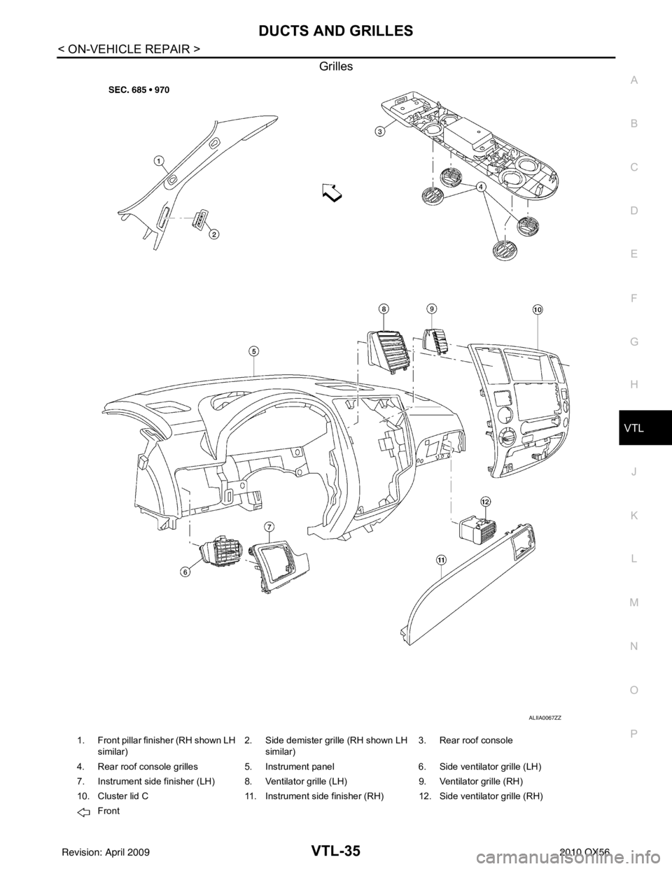
Grilles
ALIIA0067ZZ
1. Front pillar finisher (RH shown LH similar) 2. Side demister grille (RH shown LH
similar) 3. Rear roof console
4. Rear roof console grilles 5. Instrument panel 6. Side ventilator grille (LH)
7. Instrument side finisher (LH) 8. Ventilator grille (LH) 9. Ventilator grille (RH)
10. Cluster lid C 11. Instrument side finisher (RH) 12. Side ventilator grille (RH)
Front
Revision: April 20092010 QX56
Page 3998 of 4210
VTL-36
< ON-VEHICLE REPAIR >
DUCTS AND GRILLES
Removal and Installation
INFOID:0000000005147625
CENTER CONSOLE HEAT DUCT AND REAR FINISHER ASSEMBLY GRILLE
Removal
The center console must be removed and disassembled to remove the heat duct and rear finisher assembly
grille. Refer to IP-20, "
Removal and Installation".
Installation
Installation is in the reverse order of removal.
DEFROSTER NOZZLE
Removal
1. Remove the instrument panel trim. Refer to IP-12, "Removal and Installation".
2. Remove the front heater and cooling unit assembly. Refer to VTL-17, "
Removal and Installation".
3. Remove the defroster nozzle.
Installation
Installation is in the reverse order of removal.
RH AND LH SIDE DEMISTER DUCT
Removal
1. Remove the instrument panel trim. Refer to IP-12, "Removal and Installation".
2. Remove the RH or LH side demister duct screws.
3. Remove the RH or LH side demister duct.
Installation
Installation is in the reverse order of removal.
RH AND LH VENTILATOR DUCT
Removal
1. Remove the instrument panel trim. Refer to IP-12, "Removal and Installation".
2. Remove the front heater and cooling unit assembly. Refer to VTL-17, "
Removal and Installation".
3. Remove the RH or LH ventilator duct.
Installation
Installation is in the reverse order of removal.
CENTER VENTILATOR DUCT
Removal
1. Remove the instrument panel trim. Refer to IP-12, "Removal and Installation".
2. Remove the front heater and cooling unit assembly. Refer to VTL-17, "
Removal and Installation".
3. Remove the defroster nozzle.
4. Remove the RH and LH side demister ducts.
5. Remove the RH and LH ventilator ducts.
6. Remove the center ventilator duct.
Installation
Installation is in the reverse order of removal.
FLOOR DUCT
Removal
1. Remove the floor carpet. Refer to INT-16, "Removal and Installation".
2. Remove the two clips and remove the floor duct.
Installation
Installation is in the reverse order of removal.
Revision: April 20092010 QX56
Page 3999 of 4210
DUCTS AND GRILLESVTL-37
< ON-VEHICLE REPAIR >
C
DE
F
G H
J
K L
M A
B
VTL
N
O P
REAR OVERHEAD DUCTS
Removal
1. Remove the luggage side finisher lower RH. Refer to INT-19, "Removal and Installation".
2. Remove the headliner. Refer to INT-17, "
Removal and Installation".
NOTE:
The rear headliner duct connected to the rear over head duct is part of the headlining trim panel and is
replaced as an assembly.
3. Remove the two bolts and remove the rear upper and lower overhead ducts.
Installation
Installation is in the reverse order of removal.
REAR FLOOR DUCT
Removal
1. Remove the luggage side finisher lower RH. Refer to INT-19, "Removal and Installation".
2. Reposition the floor carpet out of the way.
3. Remove the two bolts and remove the rear floor duct.
Installation
Installation is in the reverse order of removal.
GRILLES
Removal
1. Remove the interior trim panels as necessary. Refer to IP-12, "Removal and Installation" or INT-14,
"Removal and Installation".
2. Remove the grille from the interior trim panel. NOTE:
To remove the rear roof console grilles, turn the grille counter-clockwise to release the grille from the rear
roof console.
Installation
Installation is in the reverse order of removal.
Revision: April 20092010 QX56
Page 4000 of 4210
WCS
WCS-1
DRIVER INFORMATION & MULTIMEDIA
C
DE
F
G H
I
J
K L
M B
SECTION WCS
A
O P
CONTENTS
WARNING CHIME SYSTEM
BASIC INSPECTION ....... .............................3
DIAGNOSIS AND REPAIR WORKFLOW ..... .....3
Work Flow ........................................................... ......3
FUNCTION DIAGNOSIS ...............................4
WARNING CHIME SYSTEM .......................... .....4
WARNING CHIME SYSTEM .......................................4
WARNING CHIME SYSTEM : System Diagram . ......4
WARNING CHIME SYSTEM : System Description
......
4
WARNING CHIME SYSTEM : Component Parts
Location ............................................................... ......
5
WARNING CHIME SYSTEM : Component De-
scription .....................................................................
5
LIGHT REMINDER WARNING CHIME ................. ......6
LIGHT REMINDER WARNING CHIME : System
Diagram .....................................................................
6
LIGHT REMINDER WARNING CHIME : System
Description ................................................................
6
LIGHT REMINDER WARNING CHIME : Compo-
nent Parts Location ...................................................
7
LIGHT REMINDER WARNING CHIME : Compo-
nent Description ........................................................
7
SEAT BELT WARNING CHIME ............................ ......7
SEAT BELT WARNING CHIME : System Diagram
......
8
SEAT BELT WARNING CHIME : System Descrip-
tion ...................................................................... ......
8
SEAT BELT WARNING CHIME : Component
Parts Location ...........................................................
9
SEAT BELT WARNING CHIME : Component De-
scription .....................................................................
9
KEY WARNING CHIME ......................................... ....10
KEY WARNING CHIME : System Diagram ............10
KEY WARNING CHIME : System Description ........10
KEY WARNING CHIME : Component Parts Loca-
tion ....................................................................... ....
11
KEY WARNING CHIME : Component Description ....11
DIAGNOSIS SYSTEM (METER) .......................12
CONSULT-III Function (METER/M&A) ....................12
DIAGNOSIS SYSTEM (BCM) ...........................14
BUZZER ................................................................. ....14
BUZZER : CONSULT-III Function (BCM - BUZZ-
ER) ..........................................................................
14
COMPONENT DIAGNOSIS .........................15
POWER SUPPLY AND GROUND CIRCUIT ....15
COMBINATION METER ........................................ ....15
COMBINATION METER : Diagnosis Procedure .....15
BCM (BODY CONTROL MODULE) ...................... ....16
BCM (BODY CONTROL MODULE) : Diagnosis
Procedure ............................................................ ....
16
METER BUZZER CIRCUIT ...............................18
Description ...............................................................18
Component Function Check ....................................18
Diagnosis Procedure ..............................................18
SEAT BELT BUCKLE SWITCH SIGNAL CIR-
CUIT ..................................................................
19
Description ...............................................................19
Component Function Check ..................................19
Diagnosis Procedure ..............................................19
Component Inspection .............................................20
KEY SWITCH SIGNAL CIRCUIT ......................21
Description ...............................................................21
Component Function Check ..................................21
Diagnosis Procedure ..............................................21
Component Inspection .............................................22
WARNING CHIME SYSTEM .............................23
Revision: April 20092010 QX56
Page 4001 of 4210

WCS-2
Wiring Diagram .......................................................23
ECU DIAGNOSIS ..................................... ...28
COMBINATION METER ................................. ...28
Reference Value .................................................. ...28
Wiring Diagram .......................................................30
Fail Safe .................................................................47
DTC Index ..............................................................48
BCM (BODY CONTROL MODULE) ..................50
Reference Value .................................................. ...50
Terminal Layout ......................................................53
Physical Values ......................................................53
Wiring Diagram .......................................................59
Fail Safe .................................................................63
DTC Inspection Priority Chart ..............................64
DTC Index ........................................................... ...64
SYMPTOM DIAGNOSIS .............................66
THE LIGHT REMINDER WARNING DOES
NOT SOUND ................................................... ...
66
Description ........................................................... ...66
Diagnosis Procedure ...............................................66
THE SEAT BELT WARNING CONTINUES
SOUNDING, OR DOES NOT SOUND ...............
67
Description ........................................................... ...67
Diagnosis Procedure ...............................................67
THE KEY WARNING DOES NOT SOUND .......68
Description ........................................................... ...68
Diagnosis Procedure ...............................................68
PRECAUTION ............................................69
PRECAUTIONS .............................................. ...69
Precaution for Supplemental Restraint System
(SRS) "AIR BAG" and "SEAT BELT PRE-TEN-
SIONER" .............................................................. ...
69
Necessary for Steering Wheel Rotation After Bat-
tery Disconnect .................................................... ...
69
Revision: April 20092010 QX56
Page 4002 of 4210
WCS
DIAGNOSIS AND REPAIR WORKFLOWWCS-3
< BASIC INSPECTION >
C
DE
F
G H
I
J
K L
M B A
O P
BASIC INSPECTION
DIAGNOSIS AND REPAIR WORKFLOW
Work FlowINFOID:0000000005146133
DETAILED FLOW
1.OBTAIN INFORMATION ABOUT SYMPTOM
Interview the customer to obtain as much informa tion as possible about the conditions and environment under
which the malfunction occurred.
>> GO TO 2
2.CHECK SYMPTOM
• Check the symptom based on the information obtained from the customer.
• Check to see if any other malfunctions are present.
>> GO TO 3
3.CHECK CONSULT-III SELF -DIAGNOSIS RESULTS
Connect CONSULT-III and perform “SELF-DIAGNOSIS”. Refer to MWI-23, "
CONSULT-III Function (METER/
M&A)".
Are self-diagnosis results normal?
YES >> GO TO 4
NO >> Repair or replace the malfunctioning parts, GO TO 5
4.NARROW DOWN MALFUNCTIONING PART S THROUGH SYMPTOM DIAGNOSIS
Perform symptom diagnosis and repair or r eplace the identified malfunctioning parts.
>> GO TO 5
5.FINAL CHECK
Check that the warning buzzer in the combination meter operates normally.
Does it operate normally?
YES >> Inspection End.
NO >> GO TO 1
Revision: April 20092010 QX56