2010 INFINITI QX56 warning
[x] Cancel search: warningPage 1978 of 4210

EXL-2
Component Function Check ...................................30
Diagnosis Procedure - Without Daytime Light Sys-
tem ..........................................................................
30
Diagnosis Procedure - With Daytime Light System
...
31
HEADLAMP (LO) CIRCUIT ...............................33
Description ........................................................... ...33
Component Function Check ...................................33
Diagnosis Procedure - Without Daytime Light Sys-
tem ..........................................................................
33
Diagnosis Procedure - With Daytime Light System
...
34
FRONT FOG LAMP CIRCUIT ...........................36
Description ........................................................... ...36
Component Function Check ...................................36
Diagnosis Procedure ..............................................36
PARKING LAMP CIRCUIT ................................38
Description ........................................................... ...38
Component Function Check ...................................38
Diagnosis Procedure - Without Daytime Light Sys-
tem ..........................................................................
38
Diagnosis Procedure - With Daytime Light System
...
41
TURN SIGNAL LAMP CIRCUIT ........................44
Description ........................................................... ...44
Component Function Check ...................................44
Diagnosis Procedure ..............................................44
OPTICAL SENSOR ...........................................47
Description ..............................................................47
Component Function Check ...................................47
Diagnosis Procedure ..............................................47
HEADLAMP AIMING SWITCH ..........................49
Description ........................................................... ...49
Diagnosis Procedure - Without Daytime Light Sys-
tem ..........................................................................
49
Diagnosis Procedure - With Daytime Light System
...
50
HEADLAMP .......................................................52
Wiring Diagram .................................................... ...52
DAYTIME LIGHT SYSTEM ................................56
Wiring Diagram .................................................... ...56
AUTO LIGHT SYSTEM ......................................62
Wiring Diagram .................................................... ...62
HEADLAMP AIMING SYSTEM (MANUAL) ......69
Wiring Diagram .................................................... ...69
FRONT FOG LAMP SYSTEM ...........................73
Wiring Diagram .................................................... ...73
TURN SIGNAL AND HAZARD WARNING
LAMP SYSTEM .............................................. ...
77
Wiring Diagram .................................................... ...77
PARKING, LICENSE PLATE AND TAIL
LAMPS SYSTEM ...............................................
84
Wiring Diagram .................................................... ...84
STOP LAMP ......................................................91
Wiring Diagram .................................................... ...91
BACK-UP LAMP ............................................ ...95
Wiring Diagram .................................................... ...95
TRAILER TOW .................................................100
Wiring Diagram .....................................................100
ECU DIAGNOSIS ......................................106
BCM (BODY CONTROL MODULE) ............... ..106
Reference Value .................................................. .106
Terminal Layout ....................................................109
Physical Values .....................................................109
Wiring Diagram .....................................................115
Fail Safe ...............................................................119
DTC Inspection Priority Chart .............................120
DTC Index ............................................................120
IPDM E/R (INTELLIGENT POWER DISTRI-
BUTION MODULE ENGINE ROOM) ................
122
Reference Value .................................................. .122
Terminal Layout ....................................................124
Physical Values .....................................................125
Wiring Diagram .....................................................130
Fail Safe ...............................................................133
DTC Index ............................................................135
SYMPTOM DIAGNOSIS ...........................136
EXTERIOR LIGHTING SYSTEM SYMPTOMS ..136
Symptom Table .................................................... .136
NORMAL OPERATING CONDITION ...............138
Description ........................................................... .138
BOTH SIDE HEADLAMPS DO NOT SWITCH
TO HIGH BEAM ................................................
139
Description ........................................................... .139
Diagnosis Procedure .............................................139
BOTH SIDE HEADLAMPS (LO) ARE NOT
TURNED ON .....................................................
140
Description ............................................................140
Diagnosis Procedure .............................................140
PARKING, LICENSE PLATE AND TAIL
LAMPS ARE NOT TURNED ON ......................
141
Description ........................................................... .141
Diagnosis Procedure .............................................141
BOTH SIDE FRONT FOG LAMPS ARE NOT
TURNED ON .....................................................
142
Description ............................................................142
Diagnosis Procedure .............................................142
Revision: April 20092010 QX56
Page 1991 of 4210

TURN SIGNAL AND HAZARD WARNING LAMPSEXL-15
< FUNCTION DIAGNOSIS >
C
DE
F
G H
I
J
K
M A
B
EXL
N
O P
TURN SIGNAL AND HA ZARD WARNING LAMPS
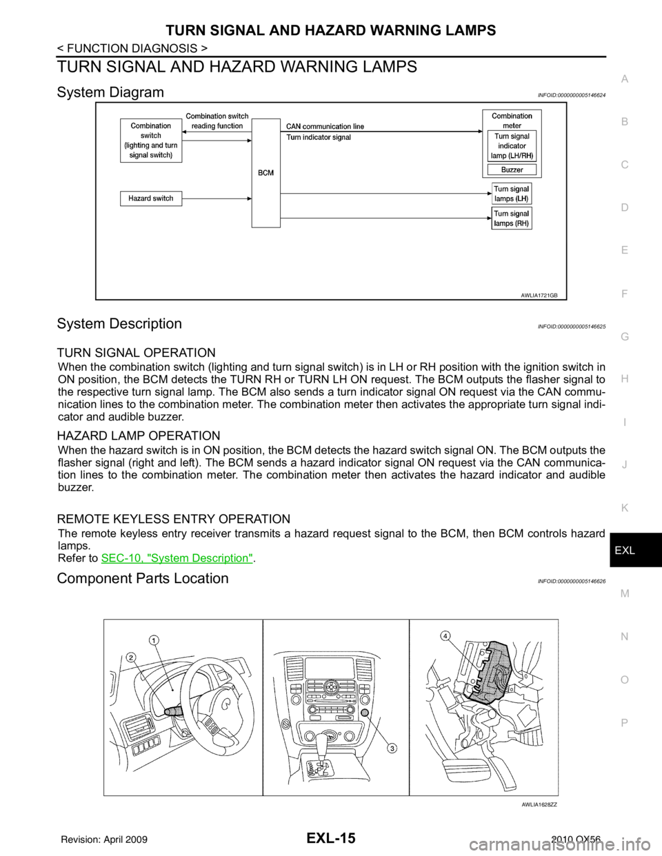
System DiagramINFOID:0000000005146624
System DescriptionINFOID:0000000005146625
TURN SIGNAL OPERATION
When the combination switch (lighting and turn signal switch) is in LH or RH position with the ignition switch in
ON position, the BCM detects the TURN RH or TURN LH ON request. The BCM outputs the flasher signal to
the respective turn signal lamp. The BCM also sends a turn indicator signal ON request via the CAN commu-
nication lines to the combination meter. The combination meter then activates the appropriate turn signal indi-
cator and audible buzzer.
HAZARD LAMP OPERATION
When the hazard switch is in ON position, the BCM detects the hazard switch signal ON. The BCM outputs the
flasher signal (right and left). The BCM sends a hazar d indicator signal ON request via the CAN communica-
tion lines to the combination meter. The combinati on meter then activates the hazard indicator and audible
buzzer.
REMOTE KEYLESS ENTRY OPERATION
The remote keyless entry receiver transmits a hazard request signal to the BCM, then BCM controls hazard
lamps.
Refer to SEC-10, "
System Description".
Component Parts LocationINFOID:0000000005146626
AWLIA1721GB
AWLIA1628ZZ
Revision: April 20092010 QX56
Page 1992 of 4210

EXL-16
< FUNCTION DIAGNOSIS >
TURN SIGNAL AND HAZARD WARNING LAMPS
Component Description
INFOID:0000000005146627
1. Combination meter M23, M24 2. Combination switch (lighting and turn signal switch) M283. Hazard switch M55
4. BCM M18, M20 (view with instrument panel removed)
Part name Description
BCM Controls turn signal and hazard flasher operation.
Combination switch (lighting and turn signal switch) Lighting and turn signal switch requests are output to the BCM.
Hazard switch Hazard flasher request signal is output to the BCM.
Combination meter Outputs turn and hazard indicator as requested by the BCM.
Revision: April 20092010 QX56
Page 1998 of 4210

EXL-22
< FUNCTION DIAGNOSIS >
DIAGNOSIS SYSTEM (IPDM E/R)
DIAGNOSIS SYSTEM (IPDM E/R)
Diagnosis DescriptionINFOID:0000000005369886
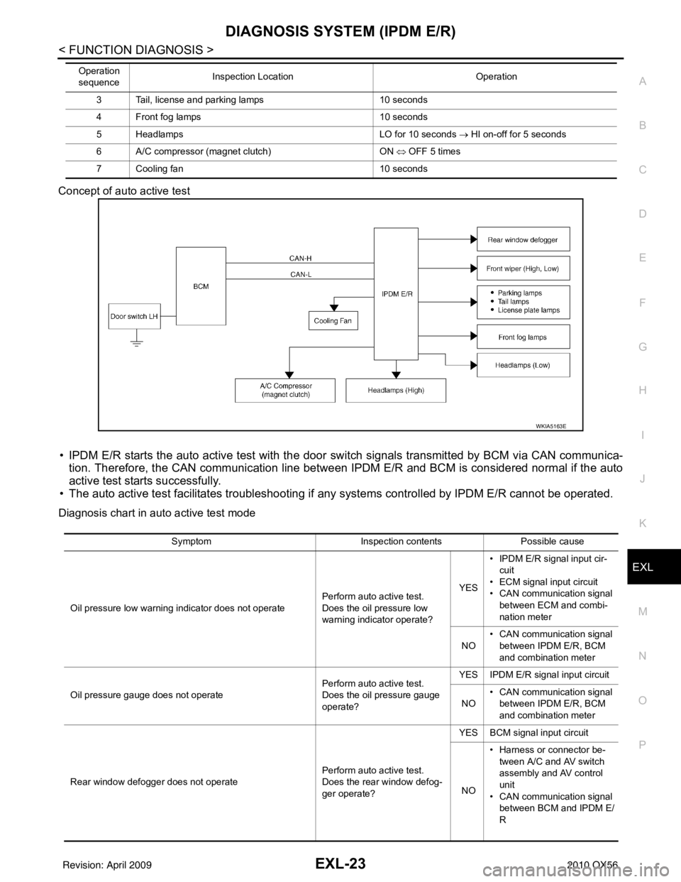
AUTO ACTIVE TEST
Description
In auto active test mode, the IPDM E/R sends a drive signal to the follo wing systems to check their operation.
• Oil pressure low/coolant pressure high warning indicator
• Oil pressure gauge
• Rear window defogger
• Front wipers
• Tail, license and parking lamps
• Front fog lamps
• Headlamps (Hi, Lo)
• A/C compressor (magnetic clutch)
• Cooling fan
Operation Procedure
1. Close the hood and front door RH, and lift the wiper a rms from the windshield (to prevent windshield dam-
age due to wiper operation).
NOTE:
When auto active test is performed with hood opened, sprinkle water on windshield before hand.
2. Turn ignition switch OFF.
3. Turn the ignition switch ON and, within 20 seconds, press the front door switch LH 10 times. Then turn the ignition switch OFF.
4. Turn the ignition switch ON within 10 seconds. Af ter that the horn sounds once and the auto active test
starts.
5. After a series of the following operations is repeated 3 times, auto active test is completed.
NOTE:
When auto active test mode has to be cancelled halfway through test, turn ignition switch OFF.
CAUTION:
• If auto active test mode cannot be actuated, check door switch system. Refer to DLK-71, "
Descrip-
tion".
• Do not start the engine.
Inspection in Auto Active Test Mode
When auto active test mode is actuated, the following 7 steps are repeated 3 times.
Operation
sequence Inspection Location
Operation
1 Rear window defogger 10 seconds
2 Front wipers LO for 5 seconds → HI for 5 seconds
WKIA4655E
Revision: April 20092010 QX56
Page 1999 of 4210

DIAGNOSIS SYSTEM (IPDM E/R)EXL-23
< FUNCTION DIAGNOSIS >
C
DE
F
G H
I
J
K
M A
B
EXL
N
O P
Concept of auto active test
• IPDM E/R starts the auto active test with the door
switch signals transmitted by BCM via CAN communica-
tion. Therefore, the CAN communication line between IPDM E/R and BCM is considered normal if the auto
active test starts successfully.
• The auto active test facilitates troubleshooting if any systems controlled by IPDM E/R cannot be operated.
Diagnosis chart in auto active test mode
3 Tail, license and parking lamps 10 seconds
4 Front fog lamps 10 seconds
5 Headlamps LO for 10 seconds → HI on-off for 5 seconds
6 A/C compressor (magnet clutch) ON ⇔ OFF 5 times
7 Cooling fan 10 seconds
Operation
sequence Inspection Location
Operation
WKIA5163E
SymptomInspection contentsPossible cause
Oil pressure low warning indicator does not operate Perform auto active test.
Does the oil pressure low
warning indicator operate?YES
• IPDM E/R signal input cir-
cuit
• ECM signal input circuit
• CAN communication signal
between ECM and combi-
nation meter
NO • CAN communication signal
between IPDM E/R, BCM
and combination meter
Oil pressure gauge does not operate Perform auto active test.
Does the oil pressure gauge
operate?YES IPDM E/R signal input circuit
NO • CAN communication signal
between IPDM E/R, BCM
and combination meter
Rear window defogger does not operate Perform auto active test.
Does the rear window defog-
ger operate?YES BCM signal input circuit
NO • Harness or connector be-
tween A/C and AV switch
assembly and AV control
unit
• CAN communication signal between BCM and IPDM E/
R
Revision: April 20092010 QX56
Page 2001 of 4210
![INFINITI QX56 2010 Factory Service Manual DIAGNOSIS SYSTEM (IPDM E/R)EXL-25
< FUNCTION DIAGNOSIS >
C
DE
F
G H
I
J
K
M A
B
EXL
N
O P
ACTIVE TEST
Te s t i t e m
TAIL&CLR REQ
[OFF/ON] ×Displays the status of the position light request signal r INFINITI QX56 2010 Factory Service Manual DIAGNOSIS SYSTEM (IPDM E/R)EXL-25
< FUNCTION DIAGNOSIS >
C
DE
F
G H
I
J
K
M A
B
EXL
N
O P
ACTIVE TEST
Te s t i t e m
TAIL&CLR REQ
[OFF/ON] ×Displays the status of the position light request signal r](/manual-img/42/57032/w960_57032-2000.png)
DIAGNOSIS SYSTEM (IPDM E/R)EXL-25
< FUNCTION DIAGNOSIS >
C
DE
F
G H
I
J
K
M A
B
EXL
N
O P
ACTIVE TEST
Te s t i t e m
TAIL&CLR REQ
[OFF/ON] ×Displays the status of the position light request signal received from BCM via CAN
communication.
HL LO REQ
[OFF/ON] ×
Displays the status of the low beam request signal received from BCM via CAN
communication.
HL HI REQ
[OFF/ON] ×Displays the status of the high beam request signal received from BCM via CAN
communication.
FR FOG REQ
[OFF/ON] ×Displays the status of the front fog lamp request signal received from BCM via
CAN communication.
FR WIP REQ
[STOP/1LOW/LOW/HI] ×
Displays the status of the front wiper request signal received from BCM via CAN
communication.
WIP AUTO STOP
[STOP P/ACT P] ×
Displays the status of the front wiper auto stop signal judged by IPDM E/R.
WIP PROT
[OFF/Block] ×
Displays the status of the front wiper fail-safe operation judged by IPDM E/R.
ST RLY REQ
[OFF/ON] Displays the status of the starter request signal received from ECM via CAN com-
munication.
IGN RLY
[OFF/ON] ×
Displays the status of the ignition relay judged by IPDM E/R.
RR DEF REQ
[OFF/ON] ×Displays the status of the rear defogger request signal received from AV control
unit via CAN communication.
OIL P SW
[OPEN/CLOSE] Displays the status of the oil pressure switch judged by IPDM E/R.
DTRL REQ
[OFF] Displays the status of the daytime light request signal received from BCM via CAN
communication.
HOOD SW
[OPEN/CLOSE] Displays the status of the hood switch judged by IPDM E/R.
THFT HRN REQ
[OFF/ON] Displays the status of the theft warning horn request signal received from BCM
via CAN communication.
HORN CHIRP
[OFF/ON] Displays the status of the horn reminder signal received from BCM via CAN com-
munication.
Monitor Item
[Unit] MAIN SIG-
NALS Description
Test item
Operation Description
REAR DEFOGGER OFF
OFF
ON Operates rear window defogger relay.
FRONT WIPER OFF
OFF
LO Operates the front wiper relay.
HI Operates the front wiper relay and front wiper high relay.
MOTOR FAN 1O
FF
2O FF
3 Operates the cooling fan relay.
4 Operates the cooling fan relay.
Revision: April 20092010 QX56
Page 2020 of 4210

EXL-44
< COMPONENT DIAGNOSIS >
TURN SIGNAL LAMP CIRCUIT
TURN SIGNAL LAMP CIRCUIT
DescriptionINFOID:0000000005146654
The BCM monitors inputs from the combination switch (lighting and turn signal switch) to determine when to
activate the turn signals. The BCM outputs voltage direction to the left and right turn signals during turn signal
operation or both during hazard warning operation. The BCM sends a turn signal indicator request to the com-
bination meter via the CAN communication lines.
The BCM performs the fast flasher operation (fail-safe) if any bulb or harness of the turn signal lamp circuit is
open.
NOTE:
Turn signal lamp blinks at normal speed when using the hazard warning lamp.
Component Function CheckINFOID:0000000005146655
1.CHECK TURN SIGNAL LAMP
CONSULT-III
1. Select "FLASHER" of BCM (FLASHER) active test item.
2. With operating the test items, check that the turn signal lamp blinks.
Does the turn signal lamp blink?
YES >> Turn signal lamp circuit is normal.
NO >> Refer to EXL-44, "
Diagnosis Procedure".
Diagnosis ProcedureINFOID:0000000005146656
Regarding Wiring Diagram information, refer to EXL-77, "Wiring Diagram".
1.CHECK TURN SIGNAL LAMP BULB
Check the applicable lamp bulb to be sure the proper bulb standard is in use and the bulb is not open.
Is the bulb OK?
YES >> GO TO 2.
NO >> Replace the bulb.
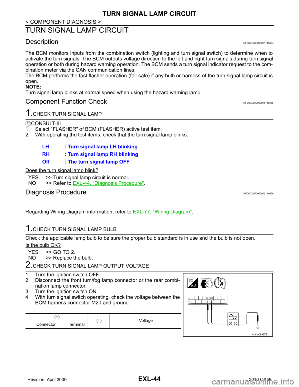
2.CHECK TURN SIGNAL LAMP OUTPUT VOLTAGE
1. Turn the ignition switch OFF.
2. Disconnect the front turn/fog lamp connector or the rear combi- nation lamp connector.
3. Turn the ignition switch ON.
4. With turn signal switch operating, check the voltage between the BCM harness connector M20 and ground.LH : Turn signal lamp LH blinking
RH : Turn signal lamp RH blinking
Off : The turn signal lamp OFF
(+)
(−) Voltage
Connector Terminal
ALLIA0896ZZ
Revision: April 20092010 QX56
Page 2053 of 4210

TURN SIGNAL AND HAZARD WARNING LAMP SYSTEMEXL-77
< COMPONENT DIAGNOSIS >
C
DE
F
G H
I
J
K
M A
B
EXL
N
O P
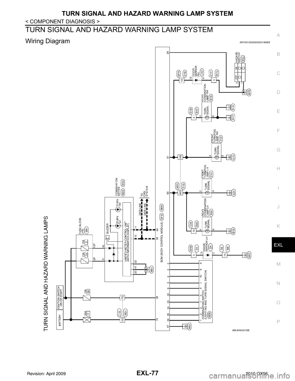
TURN SIGNAL AND HAZA RD WARNING LAMP SYSTEM
Wiring DiagramINFOID:0000000005146668
ABLWA0421GB
Revision: April 20092010 QX56