Page 3901 of 4210
TM-206
< DISASSEMBLY AND ASSEMBLY >
DISASSEMBLY
9. Remove bearing race from oil pump assembly.
10. Remove needle bearing from front sun gear.
11. Remove front sun gear assembly from front carrier assembly.NOTE:
Remove front sun gear by rotating it left and right.
12. Remove seal rings from input clutch assembly.
13. Remove front carrier assembly (with input clutch assembly and rear internal gear) from rear carrier assembly.
CAUTION:
Do not remove it with needle bearing.
SCIA6529E
SCIA2808E
SCIA5014E
SCIA2470E
SCIA5015E
Revision: April 20092010 QX56
Page 3904 of 4210
DISASSEMBLYTM-209
< DISASSEMBLY AND ASSEMBLY >
CEF
G H
I
J
K L
M A
B
TM
N
O P
22. Remove mid sun gear assembly , rear sun gear assembly and
high and low reverse clutch hub as a unit.
CAUTION:
Remove them with bearing race and needle bearing.
23. Remove high and low reverse clutch assembly from direct clutch assembly.
CAUTION:
Make sure that needle bearing is installed to the high and
low reverse clutch assembly edge surface.
24. Remove needle bearing from drum support.
25. Remove direct clutch assembly from reverse brake.
26. Remove snap ring from A/T assembly harness connector.
SCIA5018E
SCIA2306E
SCIA5198E
SCIA5019E
SCIA5021E
Revision: April 20092010 QX56
Page 3905 of 4210

TM-210
< DISASSEMBLY AND ASSEMBLY >
DISASSEMBLY
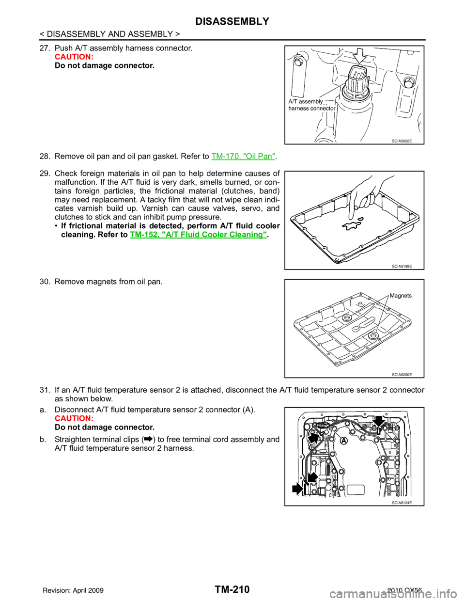
27. Push A/T assembly harness connector.CAUTION:
Do not damage connector.
28. Remove oil pan and oil pan gasket. Refer to TM-170, "
Oil Pan".
29. Check foreign materials in oil pan to help determine causes of malfunction. If the A/T fluid is very dark, smells burned, or con-
tains foreign particles, the frictional material (clutches, band)
may need replacement. A tacky film that will not wipe clean indi-
cates varnish build up. Varnish can cause valves, servo, and
clutches to stick and can inhibit pump pressure.
• If frictional material is de tected, perform A/T fluid cooler
cleaning. Refer to TM-152, "
A/T Fluid Cooler Cleaning".
30. Remove magnets from oil pan.
31. If an A/T fluid temperature sensor 2 is attached, disconnect the A/T fluid temperature sensor 2 connector
as shown below.
a. Disconnect A/T fluid temperat ure sensor 2 connector (A).
CAUTION:
Do not damage connector.
b. Straighten terminal clips ( ) to free terminal cord assembly and A/T fluid temperature sensor 2 harness.
SCIA5022E
SCIA5199E
SCIA5200E
SCIA8124E
Revision: April 20092010 QX56
Page 3920 of 4210
REPAIR FOR COMPONENT PARTSTM-225
< DISASSEMBLY AND ASSEMBLY >
CEF
G H
I
J
K L
M A
B
TM
N
O P
3. Install new oil pump housing oil seal to the oil pump housing until it is flush with the face of oil pump housing using Tool.
CAUTION:
• Do not reuse oil seal.
• Apply ATF to oil seal.
4. Install oil pump housing in oil pump cover. Tighten oil pump housing bolts to the specified torque. Refer to TM-192, "
Compo-
nent".
Front Sun Gear, 3rd One-Way ClutchINFOID:0000000005148750
COMPONENTS
DISASSEMBLY
Tool number : ST33400001 (J-26082)
SCIA5313E
SCIA5228E
1. Front sun gear 2. 3rd one-way clutch3. Snap ring
SCIA3114E
Revision: April 20092010 QX56
Page 3921 of 4210
TM-226
< DISASSEMBLY AND ASSEMBLY >
REPAIR FOR COMPONENT PARTS
1. Remove snap ring from front sun gear using suitable tool.
2. Remove 3rd one-way clutch from front sun gear.
INSPECTION
3rd One-way Clutch
• Check frictional surface for wear or damage.CAUTION:
If necessary, replace the 3rd one-way clutch.
Front Sun Gear Snap Ring
• Check for deformation, fatigue or damage.CAUTION:
If necessary, replace the snap ring.
Front Sun Gear
• Check for deformation, fatigue or damage.CAUTION:
If necessary, replace the front sun gear.
ASSEMBLY
1. Install 3rd one-way clutch in front sun gear. CAUTION:
Apply ATF to 3rd one-way clutch.
SCIA3110E
SCIA3111E
SCIA3111E
Revision: April 20092010 QX56
Page 3922 of 4210
REPAIR FOR COMPONENT PARTSTM-227
< DISASSEMBLY AND ASSEMBLY >
CEF
G H
I
J
K L
M A
B
TM
N
O P
2. Install snap ring in front sun gear using suitable tool.
3. Check operation of 3rd one-way clutch.
a. Hold oil pump assembly and turn front sun gear.
b. Check 3rd one-way clutch for correct locking and unlocking directions.
CAUTION:
If not as shown, check installation direction of 3rd one-way
clutch.
Front Carrier, Input Clutch, Rear Internal GearINFOID:0000000005148751
COMPONENTS
SCIA3110E
SCIA3131E
Revision: April 20092010 QX56
Page 3923 of 4210
TM-228
< DISASSEMBLY AND ASSEMBLY >
REPAIR FOR COMPONENT PARTS
DISASSEMBLY
1. Seal ring2. O-ring 3. Needle bearing
4. Bearing race 5. Front carrier assembly 6. Needle bearing
7. Snap ring 8. Snap ring9. Retaining plate
10. Driven plate 11. Input clutch drum 12. Drive plate
13. Rear internal gear
SCIA5244E
Revision: April 20092010 QX56
Page 3924 of 4210
REPAIR FOR COMPONENT PARTSTM-229
< DISASSEMBLY AND ASSEMBLY >
CEF
G H
I
J
K L
M A
B
TM
N
O P
1. Compress snap ring using suitable tool.
2. Remove front carrier assembly and input clutch assembly from rear internal gear.
3. Remove front carrier assembly from input clutch assembly.
a. Remove bearing race from front carrier assembly.
b. Remove needle bearing from front carrier assembly.
c. Remove snap ring from front carrier assembly. CAUTION:
Do not expand snap ring excessively.
4. Disassemble input clutch assembly.
a. Remove O-ring and seal rings from input clutch assembly.
SCIA5661E
SCIA5232E
SCIA5233E
SCIA5234E
SCIA5235E
Revision: April 20092010 QX56