Page 3849 of 4210

TM-154
< ON-VEHICLE MAINTENANCE >
A/T FLUID COOLER
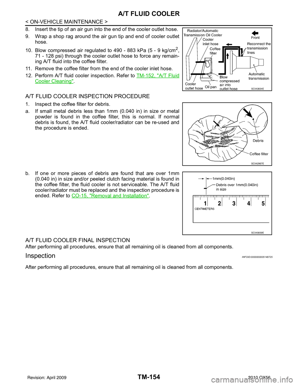
8. Insert the tip of an air gun into the end of the cooler outlet hose.
9. Wrap a shop rag around the air gun tip and end of cooler outlethose.
10. Blow compressed air regulated to 490 - 883 kPa (5 - 9 kg/cm
2,
71 - 128 psi) through the cooler outlet hose to force any remain-
ing A/T fluid into the coffee filter.
11. Remove the coffee filter from the end of the cooler inlet hose.
12. Perform A/T fluid cooler inspection. Refer to TM-152, "
A/T Fluid
Cooler Cleaning".
A/T FLUID COOLER INSPECTION PROCEDURE
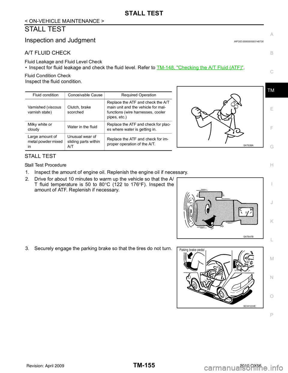
1. Inspect the coffee filter for debris.
a. If small metal debris less than 1mm (0.040 in) in size or metal
powder is found in the coffee filter, this is normal. If normal
debris is found, the A/T fluid cooler/radiator can be re-used and
the procedure is ended.
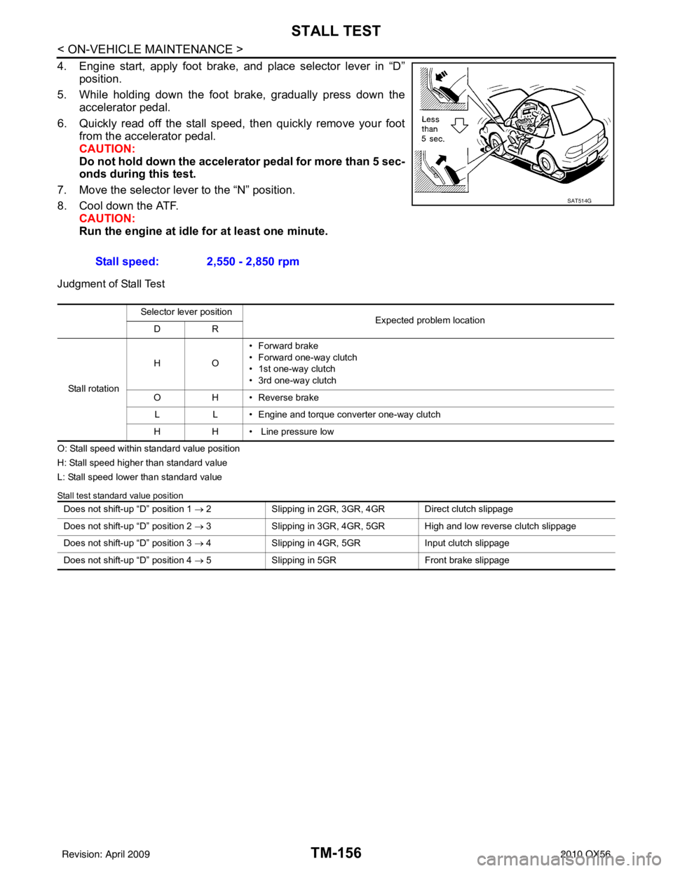
b. If one or more pieces of debris are found that are over 1mm (0.040 in) in size and/or peeled clutch facing material is found in
the coffee filter, the fluid cooler is not serviceable. The A/T fluid
cooler/radiator must be replaced and the inspection procedure is
ended. Refer to CO-15, "
Removal and Installation".
A/T FLUID COOLER FINAL INSPECTION
After performing all procedures, ensure that all remaining oil is cleaned from all components.
InspectionINFOID:0000000005148725
After performing all procedures, ensure that all remaining oil is cleaned from all components.
SCIA3834E
SCIA2967E
SCIA5659E
Revision: April 20092010 QX56
Page 3850 of 4210

STALL TESTTM-155
< ON-VEHICLE MAINTENANCE >
CEF
G H
I
J
K L
M A
B
TM
N
O P
STALL TEST
Inspection and JudgmentINFOID:0000000005148726
A/T FLUID CHECK
Fluid Leakage and Fluid Level Check
• Inspect for fluid leakage and check the fluid level. Refer to TM-148, "Checking the A/T Fluid (ATF)".
Fluid Condition Check
Inspect the fluid condition.
STALL TEST
Stall Test Procedure
1. Inspect the amount of engine oil. Replenish the engine oil if necessary.
2. Drive for about 10 minutes to warm up the vehicle so that the A/
T fluid temperature is 50 to 80 °C (122 to 176 °F). Inspect the
amount of ATF. Replenish if necessary.
3. Securely engage the parking brake so that the tires do not turn.
Fluid condition Conceivable Cause Required Operation
Varnished (viscous
varnish state) Clutch, brake
scorchedReplace the ATF and check the A/T
main unit and the vehicle for mal-
functions (wire harnesses, cooler
pipes, etc.)
Milky white or
cloudy Water in the fluidReplace the ATF and check for plac-
es where water is getting in.
Large amount of
metal powder mixed
in Unusual wear of
sliding parts within
A/T
Replace the ATF and check for im-
proper operation of the A/T.
SAT638A
SAT647B
SCIA1224E
Revision: April 20092010 QX56
Page 3851 of 4210

TM-156
< ON-VEHICLE MAINTENANCE >
STALL TEST
4. Engine start, apply foot brake, and place selector lever in “D”
position.
5. While holding down the foot brake, gradually press down the accelerator pedal.
6. Quickly read off the stall speed, then quickly remove your foot from the accelerator pedal.
CAUTION:
Do not hold down the accelerator pedal for more than 5 sec-
onds during this test.
7. Move the selector lever to the “N” position.
8. Cool down the ATF. CAUTION:
Run the engine at idle for at least one minute.
Judgment of Stall Test
O: Stall speed within standard value position
H: Stall speed higher than standard value
L: Stall speed lower than standard value
Stall test standard value position
Stall speed: 2,550 - 2,850 rpm
SAT514G
Selector lever position
Expected problem location
DR
Stall rotation HO
• Forward brake
• Forward one-way clutch
• 1st one-way clutch
• 3rd one-way clutch
O H • Reverse brake
L L • Engine and torque converter one-way clutch
H H • Line pressure low
Does not shift-up “D” position 1 → 2 Slipping in 2GR, 3GR, 4GR Direct clutch slippage
Does not shift-up “D” position 2 → 3 Slipping in 3GR, 4GR, 5GR High and low reverse clutch slippage
Does not shift-up “D” position 3 → 4 Slipping in 4GR, 5GR Input clutch slippage
Does not shift-up “D” position 4 → 5 Slipping in 5GR Front brake slippage
Revision: April 20092010 QX56
Page 3865 of 4210
TM-170
< ON-VEHICLE REPAIR >
OIL PAN
OIL PAN
Oil PanINFOID:0000000005148740
REMOVAL AND INSTALLATION
Removal
1. Drain A/T fluid. Refer to TM-150, "Changing the A/T Fluid (ATF)".
2. Remove oil pan clips (1).
3. Remove oil pan (2).
4. Remove oil pan gasket. • : Vehicle front
• : Oil pan bolts
• Drain plug (3)
5. Check foreign materials in oil pan to help determine c ause of malfunction. If the A/T fluid is very dark, has
some burned smell, or contains foreign particles, friction material (clutches, band) may need replacement.
A tacky film that will not wipe clean indicates varnish build up. Varnish can cause valves, servo, and
clutches to stick and can inhibit pump pressure.
CAUTION:
If friction material is detected, flush the transmission cooler after repair. Refer to TM-152, "
A/T
Fluid Cooler Cleaning".
6. Remove magnets from oil pan.
Installation
1. Install the oil pan magnets as shown.
AWDIA0023ZZ
SCIA5200E
SCIA5200E
Revision: April 20092010 QX56
Page 3888 of 4210
OVERHAULTM-193
< DISASSEMBLY AND ASSEMBLY >
CEF
G H
I
J
K L
M A
B
TM
N
O P
1. O-ring 2. Oil pump cover 3. O-ring
4. Oil pump housing 5. Self-sealing bolts 6. Torque converter
7. Converter housing 8. Oil pump housing oil seal 9. Bearing race
10. Needle bearing 11. O-ring 12. Front carrier assembly
13. Needle bearing 14. Snap ring 15. Front sun gear
16. 3rd one-way clutch 17. Snap ring 18. Bearing race
19. Needle bearing 20. Seal ring 21. Input clutch assembly
22. Needle bearing 23. Rear internal gear 24. Brake band
25. Mid carrier assembly 26. Needle bearing 27. Bearing race
28. Rear carrier assembly 29. Needle bearing 30. Mid sun gear
31. Seal ring 32. Rear sun gear 33. 1st one-way clutch
34. Snap ring 35. Needle bearing 36. High and low reverse clutch hub
37. Snap ring 38. Bearing race 39. Needle bearing
Revision: April 20092010 QX56
Page 3889 of 4210
TM-194
< DISASSEMBLY AND ASSEMBLY >
OVERHAUL
1. Needle bearing2. Bearing race3. High and low reverse clutch assembly
4. Needle bearing 5. Direct clutch assembly6. Reverse brake dish plate
7. Reverse brake dish plate 8. Reverse brake driven plate 9. N-spring
10. Reverse brake drive plate 11. Reverse brake retaining plate 12. Snap ring
13. D-ring 14. D-ring15. Reverse brake piston
16. Return spring 17. Spring retainer18. Snap ring
SCIA7001E
Revision: April 20092010 QX56
Page 3899 of 4210
TM-204
< DISASSEMBLY AND ASSEMBLY >
DISASSEMBLY
DISASSEMBLY
DisassemblyINFOID:0000000005148748
CAUTION:
Do not disassemble parts behind Drum Support. Refer to TM-8, "
Cross-Sectional View (2WD models)".
1. Drain A/T fluid through drain plug.
2. Remove torque converter by holding it firmly and turing while pulling straight out.
3. Check torque converter one-way clutch using a check tool as shown.
a. Insert a check tool into the groove of bearing support built into one-way clutch outer race.
b. While holding bearing support with a check tool, rotate one-way clutch spline using suitable tool.
c. Make sure that inner race rotates clockwise only. If not, replace torque converter assembly.
4. Remove bolts and converter housing from transmission case. CAUTION:
Do not scratch converter housing.
• Self-sealing bolt (A)
SCIA5010E
SCIA3171E
WCIA0662E
Revision: April 20092010 QX56
Page 3900 of 4210
DISASSEMBLYTM-205
< DISASSEMBLY AND ASSEMBLY >
CEF
G H
I
J
K L
M A
B
TM
N
O P
5. Remove O-ring from input clutch assembly.
6. Remove oil pump assembly to transmission case bolts.
7. Remove the oil pump assembly evenly from the transmission case using Tools.
CAUTION:
• Fully tighten the sliding hammer screws.
• Make sure that bearing race is installed to the oil pumpassembly edge surface.
8. Remove O-ring from oil pump assembly.
SCIA5011E
SCIA2300E
Tool number : ST25850000 (J-25721-A)
SCIA5474E
SCIA5172E
Revision: April 20092010 QX56