2010 INFINITI QX56 AUX
[x] Cancel search: AUXPage 2240 of 4210

TERMINOLOGYGI-17
< HOW TO USE THIS MANUAL >
C
DE
F
G H
I
J
K L
M B
GI
N
O P
Exhaust gas recirculation control-BPT
valve EGRC-BPT valve
BPT valve
Exhaust gas recirculation control-solenoid
valve EGRC-solenoid valve
EGR control solenoid valve
Exhaust gas recirculation temperature sen-
sor EGRT sensorExhaust gas temperature sensor
EGR temperature sensor
Flash electrically erasable programmable
read only memory FEEPROM
***
Flash erasable programmable read only
memory FEPROM
***
Flexible fuel sensor FFS***
Flexible fuel system FF system***
Fuel pressure regulato r*** Pressure regulator
Fuel pressure regulator control solenoid
valve ***
PRVR control solenoid valve
Fuel trim FT***
Heated Oxygen sensor HO2S Exhaust gas sensor
Idle air control system IAC system Idle speed control
Idle air control valve-air regulato rIACV-air regulator Air regulator
Idle air control valve-auxiliary air control
valve IACV-AAC valve
Auxiliary air control (AAC) valve
Idle air control valve-FICD solenoid valve IACV-FICD solenoid valve FICD solenoid valve
Idle air control valve-idle up control sole-
noid valve IACV-idle up control solenoid valve Idle up control solenoid valve
Idle speed control-FI pot ISC-FI pot FI pot
Idle speed control system ISC system***
Ignition control IC***
Ignition control module ICM***
Indirect fuel injection system IFI system ***
Intake air IA Air
Intake air temperature sensor IAT sensor Air temperature sensor
Knock *** Detonation
Knock sensor KS Detonation sensor
Malfunction indicator lamp MIL Check engine light
Manifold absolute pressure MAP ***
Manifold absolute pressure sensor MAPS ***
Manifold differential pressure MDP ***
Manifold differential pressure sensor MDPS ***
Manifold su rface temperature MST ***
Manifold surface temperature sensor MSTS ***
Manifold vacuum zone MVZ ***
Manifold vacuum zone sensor MVZS***
Mass air flow sensor MAFS Air flow meter
Mixture control solenoid valve MC solenoid valveAir-fuel ratio control solenoid valve
Multiport fuel injection System MFI system Fuel injection control
NEW TERM
NEW ACRONYM /
ABBREVIATION OLD TERM
Revision: April 20092010 QX56
Page 2733 of 4210

CHASSIS AND BODY MAINTENANCEMA-29
< ON-VEHICLE MAINTENANCE >
C
DE
F
G H
I
J
K L
M B
MA
N
O A
A/T FLUID : Changing the A/T Fluid (ATF)INFOID:0000000005403152
CAUTION:
If using the vehicle for towing, the A/T fluid must be replaced as specified. Refer to
MA-9, "
Introduc-
tion of Periodic Maintenance".
1. Drive the vehicle to warm up the A/T fluid to approximately 80 ° C (176 ° F).
2. Stop the engine.
3. Remove the A/T fluid level gauge.
4. Drain the A/T fluid from the drain plug hole, then install the drain plug with a new gasket. Refill the transmission with new A/T
fluid. Always refill with the same volume as the drained A/T fluid.
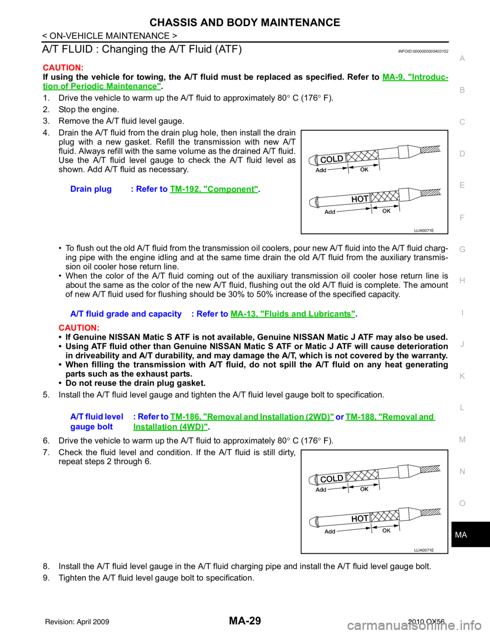
Use the A/T fluid level gauge to check the A/T fluid level as
shown. Add A/T fluid as necessary.
• To flush out the old A/T fluid from the transmission o il coolers, pour new A/T fluid into the A/T fluid charg-
ing pipe with the engine idling and at the same time drain the old A/T fluid from the auxiliary transmis-
sion oil cooler hose return line.
• When the color of the A/T fluid coming out of the aux iliary transmission oil cooler hose return line is
about the same as the color of the new A/T fluid, flushing out the old A/T fluid is complete. The amount
of new A/T fluid used for flushing should be 30% to 50% increase of the specified capacity.
CAUTION:
• If Genuine NISSAN Matic S ATF is not available, Genuine NISSAN Matic J ATF may also be used.
• Using ATF fluid other than Genuine NISSAN Matic S ATF or Matic J ATF will cause deterioration
in driveability and A/T durability, and may damage the A/T, which is not covered by the warranty.
• When filling the transmission with A/T fluid, do not spill the A/T fluid on any heat generating
parts such as the exhaust parts.
• Do not reuse the drain plug gasket.
5. Install the A/T fluid level gauge and tighten t he A/T fluid level gauge bolt to specification.
6. Drive the vehicle to warm up the A/T fluid to approximately 80 ° C (176 ° F).
7. Check the fluid level and condition. If the A/T fluid is still dirty, repeat steps 2 through 6.
8. Install the A/T fluid level gauge in the A/T fluid charging pipe and install the A/T fluid level gauge bolt.
9. Tighten the A/T fluid level gauge bolt to specification. Drain plug : Refer to
TM-192, "
Component".
LLIA0071E
A/T fluid grade and capacity : Refer to MA-13, "Fluids and Lubricants".
A/T fluid level
gauge bolt : Refer to
TM-186, "
Removal and Installation (2WD)" or TM-188, "Removal and
Installation (4WD)".
LLIA0071E
Revision: April 20092010 QX56
Page 2953 of 4210

PG
HARNESSPG-43
< COMPONENT DIAGNOSIS >
C
DE
F
G H
I
J
K L
B A
O P
N
A3 M6 W/10 : To E10
G4 M84 W/16 : To B101
A2 M7 B/5 : Passenger select unlock relay B2 M85 W/3 : Tilt motor
A3 M8 W/16 : To D2 B2 M86 W/2 : Tilt motor
A2 M9 BR/24 : To D1 B3 M87 B/5 : Rear power vent window relay (open)
A3 M10 Y/4 : To E29 B3 M89 B/5 : Rear power vent window relay (close)
A3 M11 B/1 : Parking brake switch A3 M91 W/16 : To E26
C3 M12 GR/6 : Key switch and ignition knob switch A2 M92 GR/6 : Power liftgate switch
D3 M13 BR/2 : Front passenger air bag OFF indicator D1 M93 W/24 : Display unit
A1 M14 B/2 : Diode-3 A2 M95 W/6 : Rear power vent window switch
B3 M15 W/4 : Steering lock solenoid A2 M96 BR/6 : Pedal adjusting switch
A2 M16 GR/6 : ADP steering switch C2 M98 W/16 : A/C and AV switch assembly
B2 M17 W/8 : Steering angle sensor C3 M99 BR/2 : Foot lamp LH
C2 M18 W/40 : BCM (body control module) F4 M100 BR/2 : Foot lamp RH
C2 M19 W/15 : BCM (body control module) E3 M104 W/4 : Aux jack
C2 M20 B/15 : BCM (body control module) F2 M105 Y/2 : Front passenger air bag module
C3 M21 W/4 : NATS antenna AMP. F2 M106 O/2 : Front passenger air bag module
C3 M22 W/16 : Data link connector F3 M107 B/5 : Front blower relay
B1 M23 W/12 : Combination meter D5 M108 B/6 : Yaw rate/ side/ decel G sensor
C1 M24 W/40 : Combination meter A1 M109 BR/2 : Front tweeter LH
F2 M25 B/4 : Remote keyless entry receiver D2 M110 BR/2 : Center speaker
B2 M26 W/6 : Ignition switch F2 M111 BR/2 : Front tweeter RH
B2 M28 W/16 : Combination switch C2 M112 BR/14 : BOSE speaker amp.
B2 M29 Y/6 : Combination switch C2 M113 BR/23 : BOSE speaker amp.
B3 M30 GR/8 : Combination switch A2 M116 GR/8 : Sonar system OFF switch
G4 M31 SMJ : To E152 B1 M118 B/2 : Front sonar buzzer
C3 M32 W/4 : In-vehicle sensor F2 M120 W/4 : Remote keyless entry receiver
B3 M33 W/32 : Automatic drive positioner control unit F4 M122 W/4 : Variable blower control (front)
B3 M34 W/16 : Automatic drive positioner control unit C3 M123 W/2 : Tire pressure warning check connector
C5 M35 Y/28 : Air bag diagnosis sensor unit D2 M139 B/2 : Diode-1
G4 M36 SMJ : To B149 D1 M140 B/2 : Diode-2
G3 M37 B/1 : Fuse block (J/B) C2 M141 GR/8 : 4WD shift switch
G3 M38 B/2 : Fuse block (J/B) E1 M142 B/6 : Mode door motor (front)
G3 M39 W/8 : Fuse block (J/B) E3 M143 B/6 : Air mix door motor (passenger)
A3 M40 SMJ : To B69 C1 M144 B/6 : Defroster door motor
D2 M42 W/20 : AV control unit E3 M146 GR/2 : Intake sensor
D2 M43 W/12 : AV control unit D3 M147B/6 : Air mix door motor (driver)
D2 M44 W/32 : AV control unit A3 M148 W/4 : Headlamp aiming switch
D2 M45 W/40 : AV control unit E3 M149 W/4 : Clock
B1 M47 B/2 : Sonar buzzer B1 M150 W/2 : Ignition keyhole illumination
D2 M49 B/26 : A/C auto amp. A3 M158 W/10 : To D3
D2 M50 L/26 : A/C auto amp. Console sub-harness
B3 M51 L/4 : Trailer tow relay 1 D4 M201 W/16 : To M56
B2 M52 W/2 : Combination switch D4 M202 BR/24 : To M64
D3 M53 B/3 : Front power socket LH D4 M203 W/12 : A/T shift selector
E3 M54 B/3 : Front power socket RH D5 M205 W/32 : DVD player
Revision: April 20092010 QX56
Page 3771 of 4210

TM-76
< COMPONENT DIAGNOSIS >
P1721 VEHICLE SPEED SIGNAL
P1721 VEHICLE SPEED SIGNAL
DescriptionINFOID:0000000005148624
The vehicle speed signal is transmitted from combination meter to TCM by CAN communication line. The sig-
nal functions as an auxiliary device to the output speed sensor when it is malfunctioning. The TCM will then
use the vehicle speed signal.
CONSULT-III Reference Value in Data Monitor ModeINFOID:0000000005148625
On Board Diagn osis LogicINFOID:0000000005148626
• This is not an OBD-II self-diagnostic item.
• Diagnostic trouble code “P1721 VEHICLE SPEED SIGNAL” with CONSULT-III is detected when TCM does
not receive the proper vehicle speed signal (input by CAN communication) from combination meter.
Possible CauseINFOID:0000000005148627
Harness or connectors
(The sensor circuit is open or shorted.)
DTC Confirmation ProcedureINFOID:0000000005148628
CAUTION:
Always drive vehicle at a safe speed.
NOTE:
If “DTC Confirmation Procedure” has been previously performed, always turn ignition switch “OFF”
and wait at least 10 seconds before performing the next test.
After the repair, perform the following proc edure to confirm the malfunction is eliminated.
WITH CONSULT-III
1. Turn ignition switch “ON”. (Do not start engine.)
2. Select “DATA MONITOR” mode for “TRANSMISSION” with CONSULT-III.
3. Start engine and maintain the following conditions for at least 5 consecutive seconds. ACCELE POSI: 1/8 or less
VHCL/S SE-MTR: 30 km/h (17 MPH) or more
4. If DTC is detected, go to TM-76, "
Diagnosis Procedure".
Diagnosis ProcedureINFOID:0000000005148629
1.CHECK CAN COMMUNICATION LINE
Perform the self-diagnosis. Refer TM-32, "
CONSULT-III Function (TRANSMISSION)".
Is a malfunction in the CAN communication indicated in the results?
YES >> Check CAN communication line. Refer to TM-40.
NO >> GO TO 2.
2.CHECK INPUT SIGNAL
With CONSULT-III
1. Start engine.
2. Select “ECU INPUT SIGNALS” in “DATA MONI TOR” mode for “TRANSMISSION” with CONSULT-III.
3. Drive vehicle and read out the value of “VHCL/S SE-MTR”.
OK or NG
OK >> GO TO 4.
Item name Condition Display value (km/h)
VHCL/S SE-MTR During driving Approximately matches the speedometer reading.
Item name Condition Display value (Approx.)(km/h)
VHCL/S SE-MTR During driving Approximately matches the speedometer reading.
Revision: April 20092010 QX56
Page 3845 of 4210

TM-150
< ON-VEHICLE MAINTENANCE >
A/T FLUID
Changing the A/T Fluid (ATF)
INFOID:0000000005148723
CAUTION:
If using the vehicle for towing, the A/T fl uid must be replaced as specified. Refer to MA-9, "
Introduc-
tion of Periodic Maintenance".
1. Drive the vehicle to warm up the A/T fluid to approximately 80 ° C (176 ° F).
2. Stop the engine.
3. Remove the A/T fluid level gauge.
4. Drain the A/T fluid from the drain plug hole, then install the drain plug with a new gasket. Refill the transmission with new A/T
fluid. Always refill with the same volume as the drained A/T fluid.
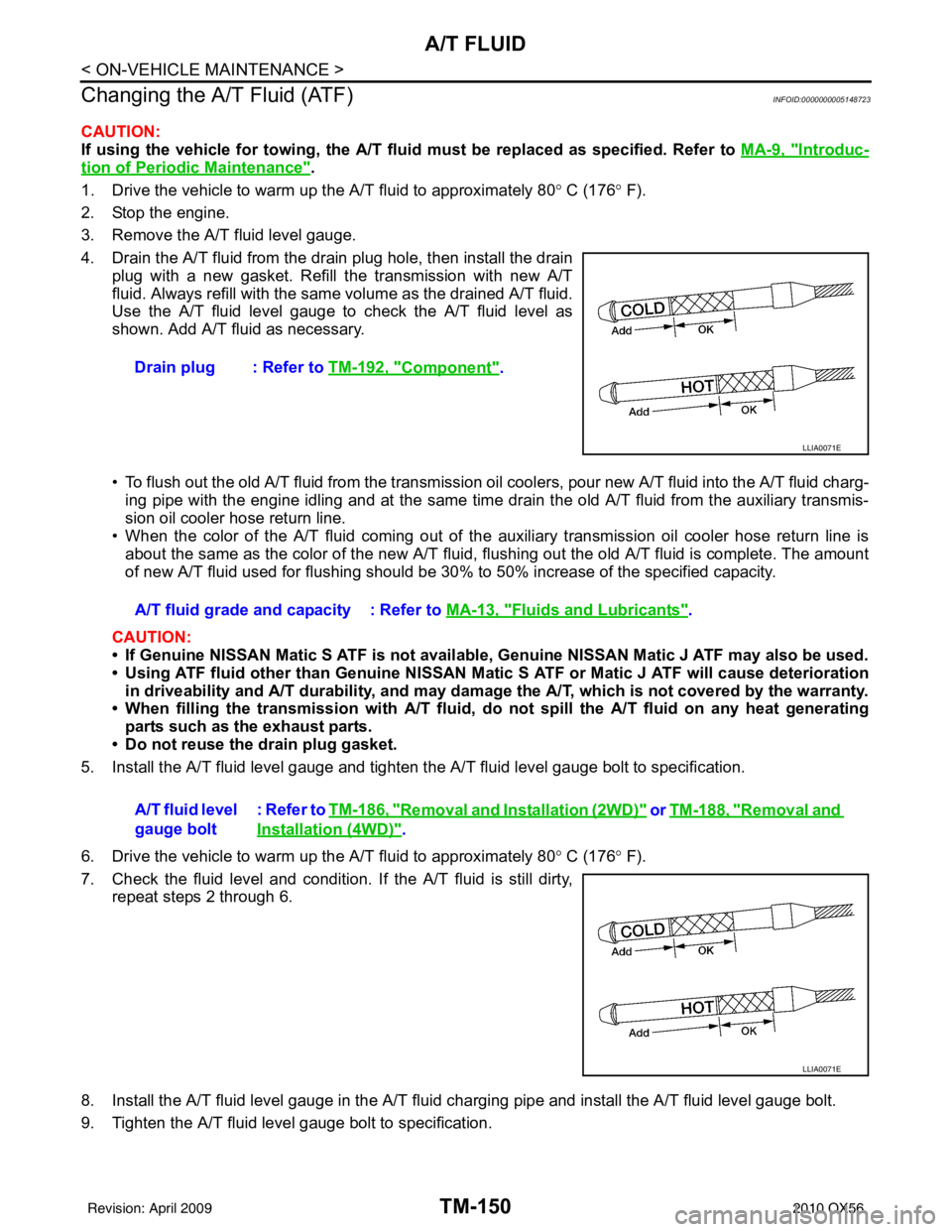
Use the A/T fluid level gauge to check the A/T fluid level as
shown. Add A/T fluid as necessary.
• To flush out the old A/T fluid from the transmission oil coolers, pour new A/T fluid into the A/T fluid charg-
ing pipe with the engine idling and at the same time drain the old A/T fluid from the auxiliary transmis-
sion oil cooler hose return line.
• When the color of the A/T fluid coming out of the auxiliary transmission oil cooler hose return line is
about the same as the color of the new A/T fluid, flushing out the old A/T fluid is complete. The amount
of new A/T fluid used for flushing should be 30% to 50% increase of the specified capacity.
CAUTION:
• If Genuine NISSAN Matic S ATF is not available, Genuine NISSAN Matic J ATF may also be used.
• Using ATF fluid other than Genuine NISSAN Matic S ATF or Matic J ATF will cause deterioration in driveability and A/T durability, and may damage the A/T, which is not covered by the warranty.
• When filling the transmission with A/T fluid, do not spill the A/T fluid on any heat generating
parts such as the exhaust parts.
• Do not reuse the drain plug gasket.
5. Install the A/T fluid level gauge and tighten the A/T fluid level gauge bolt to specification.
6. Drive the vehicle to warm up the A/T fluid to approximately 80 ° C (176 ° F).
7. Check the fluid level and condition. If the A/T fluid is still dirty, repeat steps 2 through 6.
8. Install the A/T fluid level gauge in the A/T fluid charging pipe and install the A/T fluid level gauge bolt.
9. Tighten the A/T fluid level gauge bolt to specification. Drain plug : Refer to
TM-192, "
Component".
LLIA0071E
A/T fluid grade and capacity : Refer to MA-13, "Fluids and Lubricants".
A/T fluid level
gauge bolt : Refer to TM-186, "
Removal and Installation (2WD)" or TM-188, "Removal and
Installation (4WD)".
LLIA0071E
Revision: April 20092010 QX56