Page 4013 of 4210
![INFINITI QX56 2010 Factory Service Manual WCS-14
< FUNCTION DIAGNOSIS >
DIAGNOSIS SYSTEM (BCM)
DIAGNOSIS SYSTEM (BCM)
BUZZER
BUZZER : CONSULT-III Function (BCM - BUZZER)INFOID:0000000005382325
DATA MONITOR
ACTIVE TEST
Monitor Item[Unit] Descr INFINITI QX56 2010 Factory Service Manual WCS-14
< FUNCTION DIAGNOSIS >
DIAGNOSIS SYSTEM (BCM)
DIAGNOSIS SYSTEM (BCM)
BUZZER
BUZZER : CONSULT-III Function (BCM - BUZZER)INFOID:0000000005382325
DATA MONITOR
ACTIVE TEST
Monitor Item[Unit] Descr](/manual-img/42/57032/w960_57032-4012.png)
WCS-14
< FUNCTION DIAGNOSIS >
DIAGNOSIS SYSTEM (BCM)
DIAGNOSIS SYSTEM (BCM)
BUZZER
BUZZER : CONSULT-III Function (BCM - BUZZER)INFOID:0000000005382325
DATA MONITOR
ACTIVE TEST
Monitor Item[Unit] Description
IGN ON SW [ON/OFF] Ignition switch (ON) st atus judged by ignition power supply input
KEY ON SW [ON/OFF] Key switch status
DOOR SW -DR [ON/OFF] Front door switch (driver side) status judged by BCM
LIGHT SW 1ST [ON/OFF] Lighting switch status judged by the lighting switch signal read with combination switch reading func-
tion
BUCKLE SW [ON/OFF] Seat belt buckle switch status
Test Item Description
LIGHT WARN ALM The light reminder warning operation can be checked by operating the relevant function (On/Off).
IGN KEY WARN ALM The key reminder warning operation can be checked by operating the relevant function (On/Off).
SEAT BELT WARN TEST The seat belt warning operation can be checked by operating the relevant function (On/Off).
DOOR WARNING IND The door open warning operation can be checked by operating the relevant function (On/Off).
Revision: April 20092010 QX56
Page 4014 of 4210
WCS
POWER SUPPLY AND GROUND CIRCUITWCS-15
< COMPONENT DIAGNOSIS >
C
DE
F
G H
I
J
K L
M B A
O P
COMPONENT DIAGNOSIS
POWER SUPPLY AND GROUND CIRCUIT
COMBINATION METER
COMBINATION METER : Diagnosis ProcedureINFOID:0000000005382371
Regarding Wiring Diagram information, refer to WCS-30, "Wiring Diagram".
1.CHECK FUSES
Check for blown combination meter fuses.
Is the inspection result normal?
YES >> GO TO 2
NO >> If fuse is blown, be sure to eliminate cause of malfunction before installing new fuse.
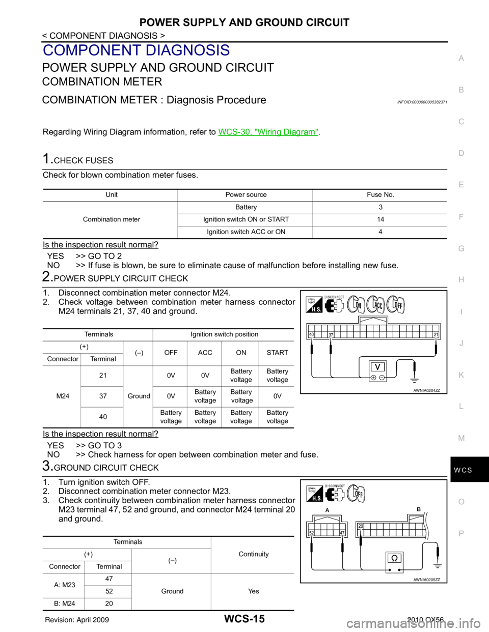
2.POWER SUPPLY CIRCUIT CHECK
1. Disconnect combination meter connector M24.
2. Check voltage between combination meter harness connector M24 terminals 21, 37, 40 and ground.
Is the inspection result normal?
YES >> GO TO 3
NO >> Check harness for open between combination meter and fuse.
3.GROUND CIRCUIT CHECK
1. Turn ignition switch OFF.
2. Disconnect combination meter connector M23.
3. Check continuity between combination meter harness connector M23 terminal 47, 52 and ground, and connector M24 terminal 20
and ground.
Unit Power source Fuse No.
Combination meter Battery 3
Ignition switch ON or START 14
Ignition switch ACC or ON 4
TerminalsIgnition switch position
(+) (–) OFF ACC ON START
Connector Terminal
M24 21
Ground 0V 0V
Battery
voltage Battery
voltage
37 0VBattery
voltage Battery
voltage 0V
40 Battery
voltage Battery
voltage Battery
voltage Battery
voltage
AWNIA0204ZZ
Te r m i n a l s
Continuity
(+)
(–)
Connector Terminal
A: M23 47
Ground Yes
52
B: M24 20
AWNIA0205ZZ
Revision: April 20092010 QX56
Page 4015 of 4210
WCS-16
< COMPONENT DIAGNOSIS >
POWER SUPPLY AND GROUND CIRCUIT
Is the inspection result normal?
YES >> Inspection End.
NO >> Check ground harness.
BCM (BODY CONTROL MODULE)
BCM (BODY CONTROL MODULE) : Diagnosis ProcedureINFOID:0000000005382372
Regarding Wiring Diagram information, refer to WCS-59, "Wiring Diagram".
1. CHECK FUSES AND FUSIBLE LINK
Check that the following fuses and fusible link are not blown.
Is the fuse blown?
YES >> Replace the blown fuse or fusible link after repairing the affected circuit.
NO >> GO TO 2
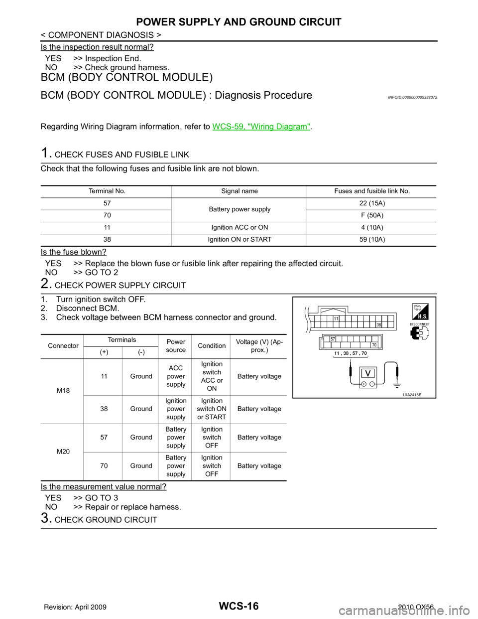
2. CHECK POWER SUPPLY CIRCUIT
1. Turn ignition switch OFF.
2. Disconnect BCM.
3. Check voltage between BCM harness connector and ground.
Is the measurement value normal?
YES >> GO TO 3
NO >> Repair or replace harness.
3. CHECK GROUND CIRCUIT
Terminal No. Signal nameFuses and fusible link No.
57 Battery power supply 22 (15A)
70 F (50A)
11 Ignition ACC or ON 4 (10A)
38 Ignition ON or START 59 (10A)
ConnectorTe r m i n a l s
Power
source Condition
Voltage (V) (Ap-
prox.)
(+) (-)
M18 11 Ground
ACC
power
supply Ignition
switch
ACC or ON Battery voltage
38 Ground Ignition
power
supply Ignition
switch ON or START Battery voltage
M20 57 Ground
Battery
power
supply Ignition
switch
OFF Battery voltage
70 Ground Battery
power
supply Ignition
switch OFF Battery voltage
LIIA2415E
Revision: April 20092010 QX56
Page 4018 of 4210
WCS
SEAT BELT BUCKLE SWITCH SIGNAL CIRCUIT
WCS-19
< COMPONENT DIAGNOSIS >
C
D E
F
G H
I
J
K L
M B A
O P
SEAT BELT BUCKLE SW ITCH SIGNAL CIRCUIT
DescriptionINFOID:0000000005146158
Transmits a seat belt buckle switch signal to the combination meter.
Component Function CheckINFOID:0000000005146159
1.CHECK COMBINATION METER INPUT SIGNAL
Select “DATA MONITOR” for “METER/M&A” and check the “SEAT BELT W/L” monitor value.
>> Inspection End.
Diagnosis ProcedureINFOID:0000000005146160
Regarding Wiring Diagram information, refer to WCS-23, "Wiring Diagram".
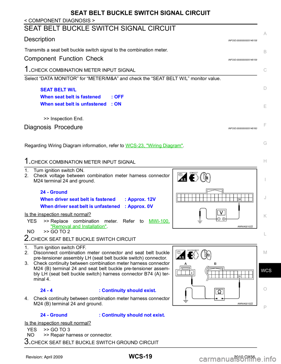
1.CHECK COMBINATION METER INPUT SIGNAL
1. Turn ignition switch ON.
2. Check voltage between combination meter harness connector M24 terminal 24 and ground.
Is the inspection result normal?
YES >> Replace combination meter. Refer to MWI-100,
"Removal and Installation".
NO >> GO TO 2
2.CHECK SEAT BELT BUCKLE SWITCH CIRCUIT
1. Turn ignition switch OFF.
2. Disconnect combination meter connector and seat belt buckle pre-tensioner assembly LH (seat belt buckle switch) connector.
3. Check continuity between combination meter harness connector M24 (B) terminal 24 and seat belt buckle pre-tensioner assem-
bly LH (seat belt buckle switch ) harness connector B74 (A) ter-
minal 4.
4. Check continuity between combination meter harness connector M24 (B) terminal 24 and ground.
Is the inspection result normal?
YES >> GO TO 3
NO >> Repair harness or connector.
3.CHECK SEAT BELT BUCKLE SWITCH GROUND CIRCUIT SEAT BELT W/L
When seat belt is fastened : OFF
When seat belt is unfastened : ON
24 - Ground
When driver seat belt is fastened : Approx. 12V
When driver seat belt is unfastened : Approx. 0V
AWNIA0212ZZ
24 - 4
: Continuity should exist.
24 - Ground : Continuity should not exist.
AWNIA0213ZZ
Revision: April 20092010 QX56
Page 4019 of 4210
WCS-20
< COMPONENT DIAGNOSIS >
SEAT BELT BUCKLE SWITCH SIGNAL CIRCUIT
Check continuity between seat belt buckle pre-tensioner assembly
LH (seat belt buckle switch) harness connector B74 terminal 3 and
ground.
Is the inspection result normal?
YES >> Inspection End.
NO >> Repair harness or connector.
Component InspectionINFOID:0000000005146161
1.CHECK SEAT BELT BUCKLE SWITCH
1. Turn ignition switch OFF.
2. Disconnect the seat belt buckle pre-tensioner assembly LH (seat belt buckle switch) connector.
3. Check continuity between terminals 3 and 4.
Is the inspection result normal?
YES >> Inspection End.
NO >> Replace the seat belt buckle pre-tensioner assembly LH (seat belt buckle switch).
3 - Ground : Continuity should exist.
AWNIA0288ZZ
3– 4
When seat belt is
fastened
: Continuity should not exist.
When seat belt is
unfastened : Continuity should exist.
AWNIA0289ZZ
Revision: April 20092010 QX56
Page 4020 of 4210
WCS
KEY SWITCH SIGNAL CIRCUITWCS-21
< COMPONENT DIAGNOSIS >
C
DE
F
G H
I
J
K L
M B A
O P
KEY SWITCH SIGNAL CIRCUIT
DescriptionINFOID:0000000005146162
Transmits a key switch signal to the BCM.
Component Function CheckINFOID:0000000005146163
1.CHECK BCM INPUT SIGNAL
Select “DATA MONITOR” for “BCM” and c heck the “KEY ON SW” monitor value.
>> Inspection End.
Diagnosis ProcedureINFOID:0000000005146164
Regarding Wiring Diagram information, refer to WCS-23, "Wiring Diagram".
1.CHECK FUSE
Check if the key switch and ignition knob switch 10A fuse (No. 62, located in the fuse and relay box) is blown.
Is the fuse blown?
YES >> Be sure to repair the cause of malfunction before installing new fuse.
NO >> GO TO 2
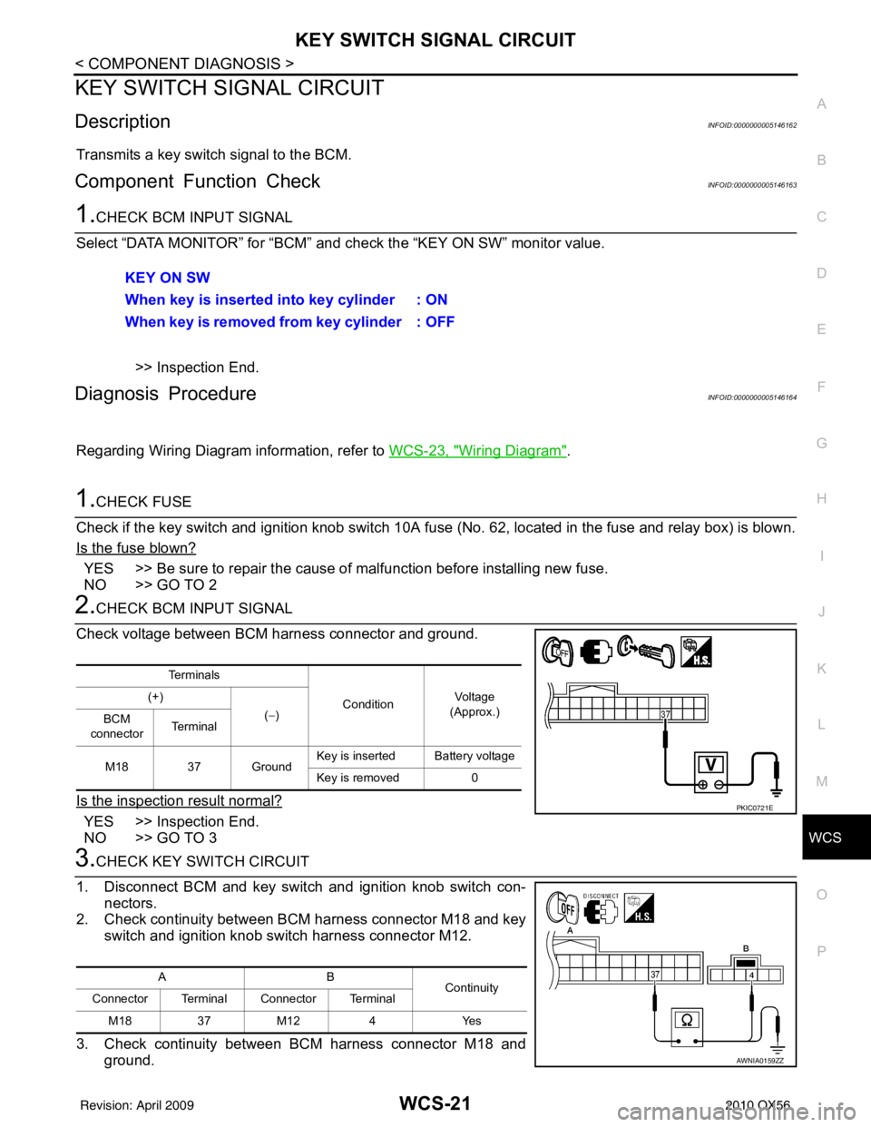
2.CHECK BCM INPUT SIGNAL
Check voltage between BCM harness connector and ground.
Is the inspection result normal?
YES >> Inspection End.
NO >> GO TO 3
3.CHECK KEY SWITCH CIRCUIT
1. Disconnect BCM and key switch and ignition knob switch con- nectors.
2. Check continuity between BCM harness connector M18 and key
switch and ignition knob switch harness connector M12.
3. Check continuity between BCM harness connector M18 and ground.KEY ON SW
When key is inserted into key cylinder : ON
When key is removed from key cylinder : OFF
Te r m i n a l s
ConditionVo l ta g e
(Approx.)
(+)
(−)
BCM
connector Te r m i n a l
M18 37 Ground Key is inserted Battery voltage
Key is removed 0
PKIC0721E
AB
Continuity
Connector Terminal Connector Terminal
M18 37M12 4 Yes
AWNIA0159ZZ
Revision: April 20092010 QX56
Page 4021 of 4210
WCS-22
< COMPONENT DIAGNOSIS >
KEY SWITCH SIGNAL CIRCUIT
Is the inspection result normal?
YES >> GO TO 4
NO >> Repair harness or connector.
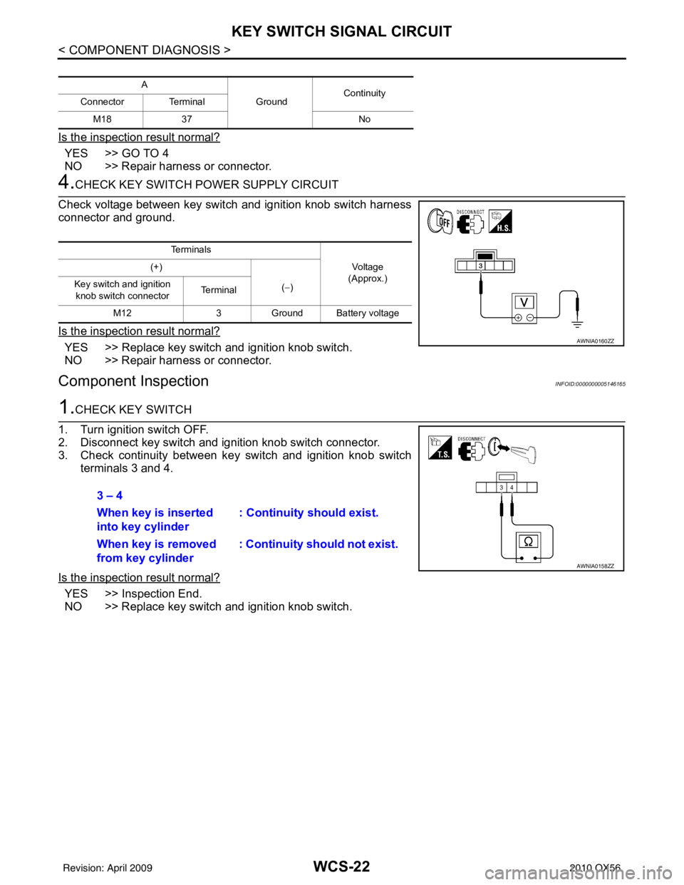
4.CHECK KEY SWITCH POWER SUPPLY CIRCUIT
Check voltage between key switch and ignition knob switch harness
connector and ground.
Is the inspection result normal?
YES >> Replace key switch and ignition knob switch.
NO >> Repair harness or connector.
Component InspectionINFOID:0000000005146165
1.CHECK KEY SWITCH
1. Turn ignition switch OFF.
2. Disconnect key switch and ignition knob switch connector.
3. Check continuity between key switch and ignition knob switch terminals 3 and 4.
Is the inspection result normal?
YES >> Inspection End.
NO >> Replace key switch and ignition knob switch.
A GroundContinuity
Connector Terminal
M18 37 No
Te r m i n a l s
Voltag e
(Approx.)
(+)
(−)
Key switch and ignition
knob switch connector Terminal
M12 3Ground Battery voltage
AWNIA0160ZZ
3 – 4
When key is inserted
into key cylinder : Continuity should exist.
When key is removed
from key cylinder : Continuity should not exist.
AWNIA0158ZZ
Revision: April 20092010 QX56
Page 4027 of 4210
WCS-28
< ECU DIAGNOSIS >
COMBINATION METER
ECU DIAGNOSIS
COMBINATION METER
Reference ValueINFOID:0000000005382408
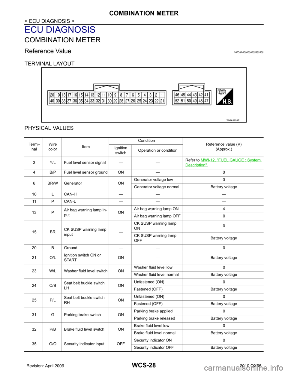
TERMINAL LAYOUT
PHYSICAL VALUES
WKIA5724E
Te r m i -nal Wire
color Item Condition
Reference value (V)
(Approx.)
Ignition
switch Operation or condition
3 Y/L Fuel level sensor signal — —Refer to MWI-12, "
FUEL GAUGE : System
Description".
4 B/P Fuel level sensor ground ON —0
6 BR/W Generator ONGenerator voltage low
0
Generator voltage normal Battery voltage
10 L CAN-H —— —
11 P C A N - L —— —
13 P Air bag warning lamp in-
put ONAir bag warning lamp ON
4
Air bag warning lamp OFF 0
15 BR CK SUSP warning lamp
input —CK SUSP warning lamp
ON
0
CK SUSP warning lamp
OFF Battery voltage
20 B Ground —— 0
21 O/L Ignition switch ON or
START ON
— Battery voltage
23 W/L Washer fluid level switch ON Washer fluid level low
0
Washer fluid level normal Battery voltage
24 O/B Seat belt buckle switch
LH ONUnfastened (ON)
0
Fastened (OFF) Battery voltage
25 P/L Seat belt buckle switch
RH ONUnfastened (ON)
0
Fastened (OFF) Battery voltage
31 G Parking brake switch ON Parking brake applied
0
Parking brake released Battery voltage
32 P/B Brake fluid level switch ON Brake fluid level low
0
Brake fluid level normal Battery voltage
35 G/O Security indicator input OFF Security indicator ON
0
Security indicator OFF Battery voltage
Revision: April 20092010 QX56