2010 INFINITI QX56 transmission
[x] Cancel search: transmissionPage 3700 of 4210
DIAGNOSIS AND REPAIR WORKFLOWTM-5
< BASIC INSPECTION >
CEF
G H
I
J
K L
M A
B
TM
N
O P
BASIC INSPECTION
DIAGNOSIS AND REPAIR WORKFLOW
Work FlowINFOID:0000000005148505
INTRODUCTION
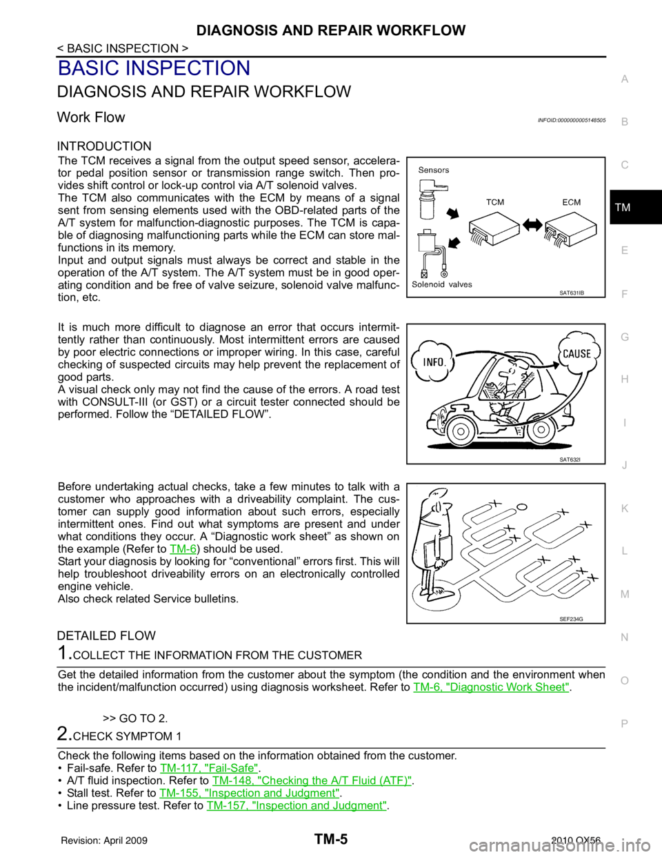
The TCM receives a signal from the output speed sensor, accelera-
tor pedal position sensor or transmission range switch. Then pro-
vides shift control or lock-up control via A/T solenoid valves.
The TCM also communicates with the ECM by means of a signal
sent from sensing elements used wit h the OBD-related parts of the
A/T system for malfunction-diagnostic purposes. The TCM is capa-
ble of diagnosing malfunctioning parts while the ECM can store mal-
functions in its memory.
Input and output signals must always be correct and stable in the
operation of the A/T system. T he A/T system must be in good oper-
ating condition and be free of valve seizure, solenoid valve malfunc-
tion, etc.
It is much more difficult to diagnose an error that occurs intermit-
tently rather than continuously. Most intermittent errors are caused
by poor electric connections or impr oper wiring. In this case, careful
checking of suspected circuits may help prevent the replacement of
good parts.
A visual check only may not find t he cause of the errors. A road test
with CONSULT-III (or GST) or a circuit tester connected should be
performed. Follow the “DETAILED FLOW”.
Before undertaking actual checks, take a few minutes to talk with a
customer who approaches with a driveability complaint. The cus-
tomer can supply good information about such errors, especially
intermittent ones. Find out what symptoms are present and under
what conditions they occur. A “Diagnostic work sheet” as shown on
the example (Refer to TM-6
) should be used.
Start your diagnosis by looking for “conventional” errors first. This will
help troubleshoot driveability errors on an electronically controlled
engine vehicle.
Also check related Service bulletins.
DETAILED FLOW
1.COLLECT THE INFORMATION FROM THE CUSTOMER
Get the detailed information from the customer about the symptom (the condition and the environment when
the incident/malfunction occurred) us ing diagnosis worksheet. Refer to TM-6, "
Diagnostic Work Sheet".
>> GO TO 2.
2.CHECK SYMPTOM 1
Check the following items based on the in formation obtained from the customer.
• Fail-safe. Refer to TM-117, "
Fail-Safe".
• A/T fluid inspection. Refer to TM-148, "
Checking the A/T Fluid (ATF)".
• Stall test. Refer to TM-155, "
Inspection and Judgment".
• Line pressure test. Refer to TM-157, "
Inspection and Judgment".
SAT631IB
SAT632I
SEF234G
Revision: April 20092010 QX56
Page 3704 of 4210
A/T CONTROL SYSTEMTM-9
< FUNCTION DIAGNOSIS >
CEF
G H
I
J
K L
M A
B
TM
N
O P
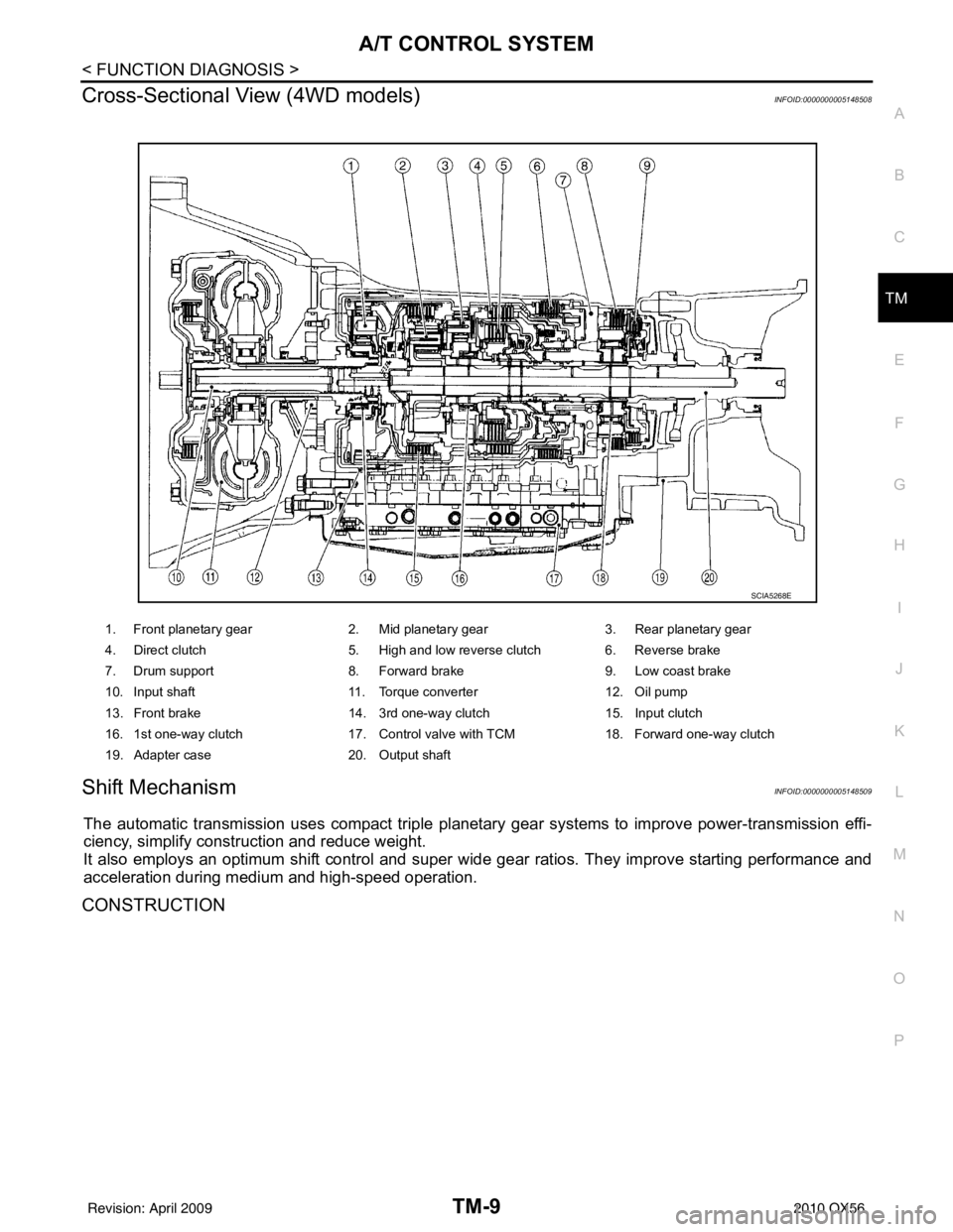
Cross-Sectional View (4WD models)INFOID:0000000005148508
Shift MechanismINFOID:0000000005148509
The automatic transmission uses compact triple planet ary gear systems to improve power-transmission effi-
ciency, simplify construction and reduce weight.
It also employs an optimum shift control and super wide gear ratios. They improve starting performance and
acceleration during medium and high-speed operation.
CONSTRUCTION
1. Front planetary gear 2. Mid planetary gear 3. Rear planetary gear
4. Direct clutch 5. High and low reverse clutch 6. Reverse brake
7. Drum support 8. Forward brake 9. Low coast brake
10. Input shaft 11. Torque converter 12. Oil pump
13. Front brake 14. 3rd one-way clutch 15. Input clutch
16. 1st one-way clutch 17. Control valve with TCM 18. Forward one-way clutch
19. Adapter case 20. Output shaft
SCIA5268E
Revision: April 20092010 QX56
Page 3706 of 4210
A/T CONTROL SYSTEMTM-11
< FUNCTION DIAGNOSIS >
CEF
G H
I
J
K L
M A
B
TM
N
O P
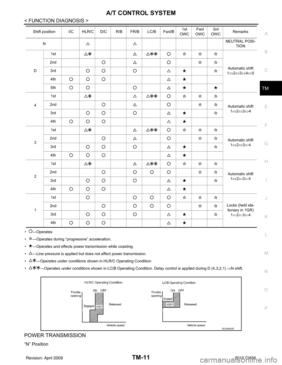
• —Operates
• —Operates during “pro gressive” acceleration.
• —Operates and effects power transmission while coasting.
• —Line pressure is applied but does not affect power transmission.
• —Operates under conditions shown in HLR/C Operating Condition
• —Operates under conditions shown in LC/B Operating Condition. Delay control is applied during D (4,3,2,1) ⇒N shift.
POWER TRANSMISSION
“N” Position
NNEUTRAL POSI-
TION
D 1st
Automatic shift
1 ⇔ 2⇔ 3⇔ 4⇔ 5
2nd
3rd
4th
5th1st
Automatic shift1⇔ 2⇔ 3⇔ 4
4
2nd
3rd
4th
3 1st
Automatic shift1⇔ 2⇔ 3⇐4
2nd
3rd 4th
2 1st
Automatic shift1⇔ 2⇐3 ⇐4
2nd
3rd
4th
1 1st
Locks (held sta-tionary in 1GR)
1⇐ 2⇐3 ⇐4
2nd
3rd4th
Shift position I/C HLR/C D/C R/B FR/B LC/B Fwd/B
1st
OWC Fwd
OWC 3rd
OWC Remarks
SCIA5642E
Revision: April 20092010 QX56
Page 3715 of 4210
TM-20
< FUNCTION DIAGNOSIS >
A/T CONTROL SYSTEM
TCM Function
INFOID:0000000005148510
The function of the TCM is to:
• Receive input signals sent from various switches and sensors.
• Determine required line pressure, shifting poi nt, lock-up operation, and engine brake operation.
• Send required output signals to the respective solenoids.
CONTROL SYSTEM OUTLINE
The automatic transmission senses vehicle operating conditions through vari ous sensors or signals. It always
controls the optimum shift position and reduces shifting and lock-up shocks.
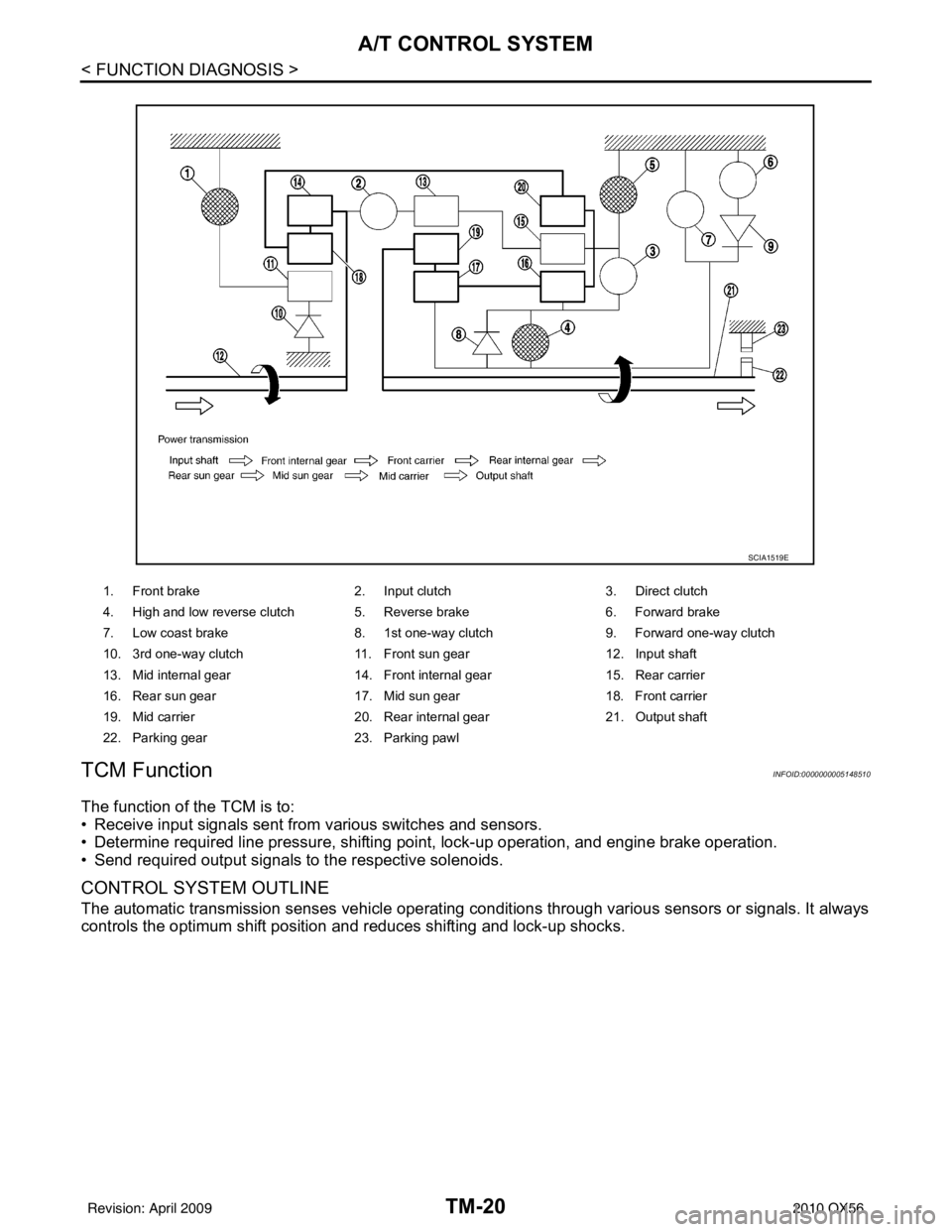
1. Front brake 2. Input clutch3. Direct clutch
4. High and low reverse clutch 5. Reverse brake 6. Forward brake
7. Low coast brake 8. 1st one-way clutch 9. Forward one-way clutch
10. 3rd one-way clutch 11. Front sun gear12. Input shaft
13. Mid internal gear 14. Front internal gear15. Rear carrier
16. Rear sun gear 17. Mid sun gear18. Front carrier
19. Mid carrier 20. Rear internal gear21. Output shaft
22. Parking gear 23. Parking pawl
SCIA1519E
Revision: April 20092010 QX56
Page 3716 of 4210
A/T CONTROL SYSTEMTM-21
< FUNCTION DIAGNOSIS >
CEF
G H
I
J
K L
M A
B
TM
N
O P
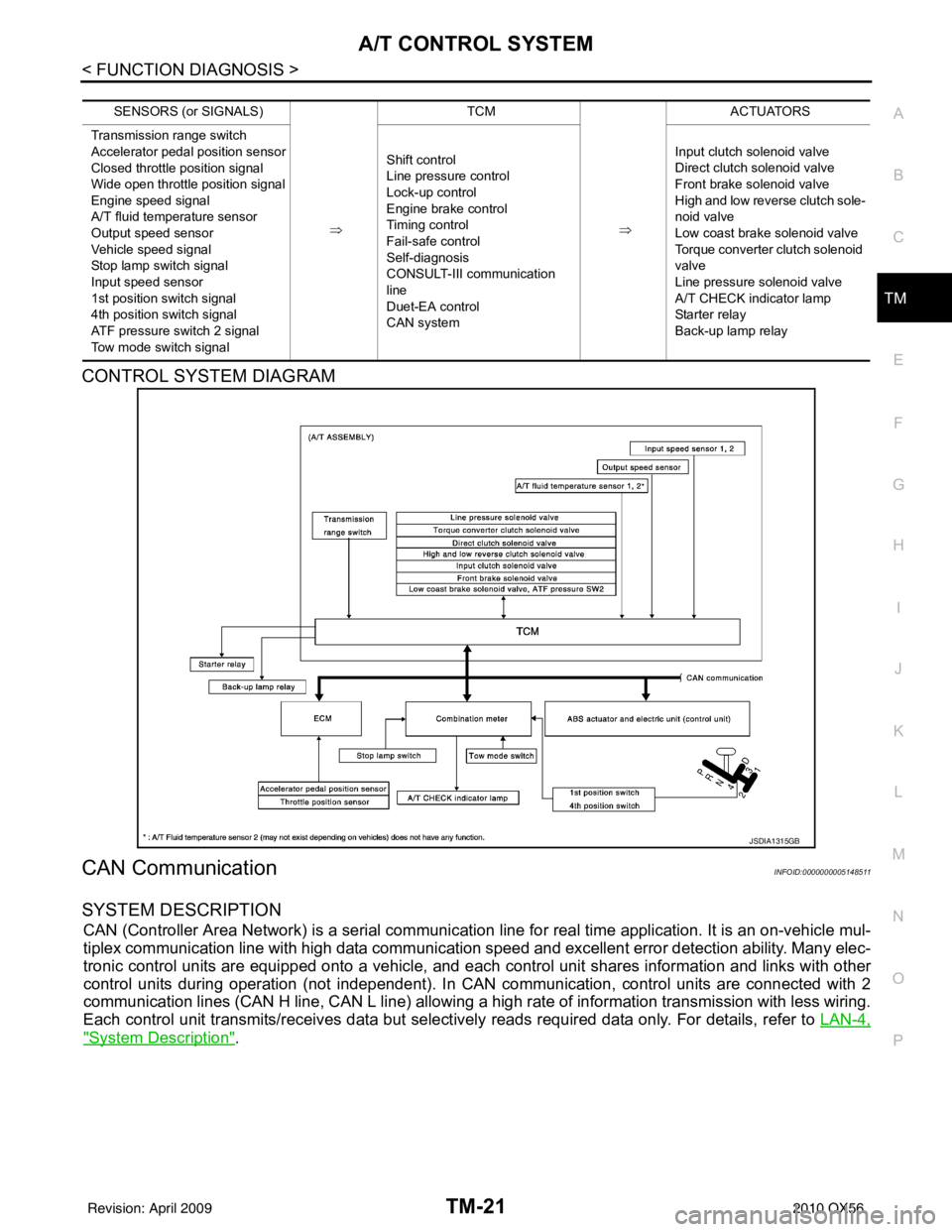
CONTROL SYSTEM DIAGRAM
CAN CommunicationINFOID:0000000005148511
SYSTEM DESCRIPTION
CAN (Controller Area Network) is a serial communication line for real time application. It is an on-vehicle mul-
tiplex communication line with high data communication speed and excellent error detection ability. Many elec-
tronic control units are equipped onto a vehicle, and each control unit shares information and links with other
control units during operation (not independent). In CAN communication, control units are connected with 2
communication lines (CAN H line, CAN L line) allowing a high rate of information transmission with less wiring.
Each control unit transmits/receives data but selectively reads required data only. For details, refer to LAN-4,
"System Description".
SENSORS (or SIGNALS)
⇒TCM
⇒ACTUATORS
Transmission range switch
Accelerator pedal position sensor
Closed throttle position signal
Wide open throttle position signal
Engine speed signal
A/T fluid temperature sensor
Output speed sensor
Vehicle speed signal
Stop lamp switch signal
Input speed sensor
1st position switch signal
4th position switch signal
ATF pressure switch 2 signal
Tow mode switch signal Shift control
Line pressure control
Lock-up control
Engine brake control
Timing control
Fail-safe control
Self-diagnosis
CONSULT-III co
mmunication
line
Duet-EA control
CAN system Input clutch solenoid valve
Direct clutch solenoid valve
Front brake solenoid valve
High and low reverse clutch sole-
noid valve
Low coast brake solenoid valve
Torque converter clutch solenoid
valve
Line pressure solenoid valve
A/T CHECK indicator lamp
Starter relay
Back-up lamp relay
JSDIA1315GB
Revision: April 20092010 QX56
Page 3717 of 4210

TM-22
< FUNCTION DIAGNOSIS >
A/T CONTROL SYSTEM
Input/Output Signal of TCM
INFOID:0000000005148512
*1: Spare for output speed sensor
*2: Spare for accelerator pedal position signal
*3: If these input and output signals are different, the TCM triggers the fail-safe function.
*4: CAN comm unications
*5: Used as a condition for starting self-diagnostics; if self-diagnostics are not started, it is judged that there is some kin d of error.
*6: A/T fluid temperature sensor 2 does not have any function.
Line Pressure ControlINFOID:0000000005148513
• When an input torque signal equivalent to the engine drive force is sent from the ECM to the TCM, the TCM
controls the line pressure solenoid.
Control item Line
pres- sure
control Vehicle
speed
control S h i f t
control Lock-up
control Engine
brake
control Fail-safe
function (*3) Self-diag-
nostics
function
Input Accelerator pedal position signal
(*4)XXXXX X X
Output speed sensor X X X X X X
Vehicle speed signal
(*1) (*4)XXXX X
Closed throttle position signal
(*4)(*2) X (*2) X X (*2) X(*5) X
Wide open throttle position signal
(*4)(*2) X (*2) X (*2) X(*5) X
Input speed sensor 1 X XXX X
Input speed sensor 2
(for 4th speed only) XX X
X X
Engine speed signals
(*4)XX
Transmission range switch X X X X X X X
Stop lamp switch signal
(*4)XXX (*5) X
A/T fluid temperature sensors 1, 2 (*6) X X X X X X X
ASCD Operation signal
(*4)XXXX
Overdrive cancel sig-
nal
(*4)XXX
TCM power supply voltage signal X X X X X X
Output Direct clutch solenoid
X XX X
Input clutch solenoid X XX X
High and low reverse clutch solenoid X XX X
Front brake solenoid X XX X
Low coast brake solenoid (ATF pressure
switch 2) XX X X X
Line pressure solenoid X X X X X X X
TCC solenoid XX X
Starter relay XX
Revision: April 20092010 QX56
Page 3720 of 4210
A/T CONTROL SYSTEMTM-25
< FUNCTION DIAGNOSIS >
CEF
G H
I
J
K L
M A
B
TM
N
O P
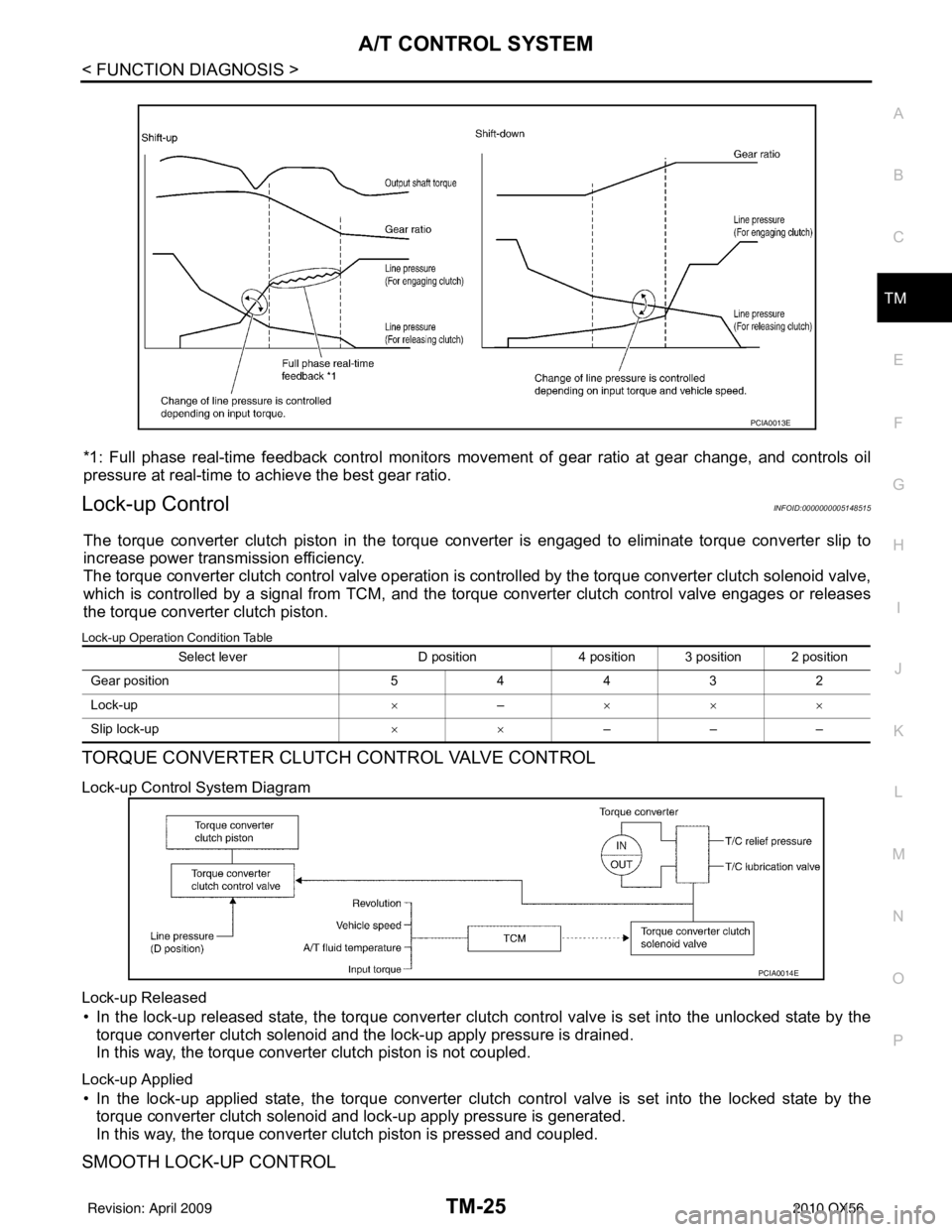
*1: Full phase real-time feedback control monitors move ment of gear ratio at gear change, and controls oil
pressure at real-time to achieve the best gear ratio.
Lock-up ControlINFOID:0000000005148515
The torque converter clutch piston in the torque conv erter is engaged to eliminate torque converter slip to
increase power transmission efficiency.
The torque converter clutch control valve operation is controlled by the torque conver ter clutch solenoid valve,
which is controlled by a signal from TCM, and the torque converter clutch control valve engages or releases
the torque converter clutch piston.
Lock-up Operation Condition Table
TORQUE CONVERTER CLUTCH CONTROL VALVE CONTROL
Lock-up Control System Diagram
Lock-up Released
• In the lock-up released state, the torque converter clutch control valve is set into the unlocked state by the
torque converter clutch solenoid and the lock-up apply pressure is drained.
In this way, the torque converter clutch piston is not coupled.
Lock-up Applied
• In the lock-up applied state, the torque converter clutch control valve is set into the locked state by the
torque converter clutch solenoid and lock-up apply pressure is generated.
In this way, the torque converter clutch piston is pressed and coupled.
SMOOTH LOCK-UP CONTROL
PCIA0013E
Select lever D position4 position 3 position 2 position
G ear p osit io n 54432
Lock-up ×– ×××
Slip lock-up ××–––
PCIA0014E
Revision: April 20092010 QX56
Page 3725 of 4210
TM-30
< FUNCTION DIAGNOSIS >
ON BOARD DIAGNOSTIC (OBD) SYSTEM
ON BOARD DIAGNOSTIC (OBD) SYSTEM
IntroductionINFOID:0000000005148521
The A/T system has two self-diagnostic systems.
The first is the emission-related on board diagnostic syst em (OBD-II) performed by the TCM in combination
with the ECM. The malfunction is indicated by the MI L (malfunction indicator lamp) and is stored as a DTC in
the ECM memory but not the TCM memory.
The second is the TCM original self-diagnosis indicated by the A/T CHECK indicator lamp. The malfunction is
stored in the TCM memory. The detected items are ov erlapped with OBD-II self-diagnostic items. For detail,
refer to TM-32, "
CONSULT-III Function (TRANSMISSION)".
OBD-II Function for A/T SystemINFOID:0000000005148522
The ECM provides emission-related on board diagnostic (O BD-II) functions for the A/T system. One function
is to receive a signal from the TCM used with OBD-relat ed parts of the A/T system. The signal is sent to the
ECM when a malfunction occurs in the corresponding OBD-re lated part. The other function is to indicate a
diagnostic result by means of the MIL (malfunction indi cator lamp) on the instrument panel. Sensors, switches
and solenoid valves are used as sensing elements.
The MIL automatically illuminates in One or Two Trip Detection Logic when a malfunction is sensed in relation
to A/T system parts.
One or Two Trip Detection Logic of OBD-IIINFOID:0000000005148523
ONE TRIP DETECTION LOGIC
If a malfunction is sensed during the first test drive, the MIL will illuminate and the malfunction will be stored in
the ECM memory as a DTC. The TCM is not provided with such a memory function.
TWO TRIP DETECTION LOGIC
When a malfunction is sensed during the first test drive, it is stored in the ECM memory as a 1st trip DTC
(diagnostic trouble code) or 1st trip freeze frame data. At this point, the MIL will not illuminate. — 1st Trip
If the same malfunction as that experienced during the fi rst test drive is sensed during the second test drive,
the MIL will illuminate. — 2nd Trip
The “Trip” in the “One or Two Trip Detection Logic” means a driving mode in which self-diagnosis is performed
during vehicle operation.
OBD-II Diagnostic Trouble Code (DTC)INFOID:0000000005148524
HOW TO READ DTC AND 1ST TRIP DTC
DTC and 1st trip DTC can be read by the following methods.
( with CONSULT-III or GST) CONSULT-III or GST (Generic Scan Tool) Examples: P0705, P0720 etc.
These DTC are prescribed by SAE J2012.
(CONSULT-III also displays the malfunctioning component or system.)
• 1st trip DTC No. is the same as DTC No.
• Output of the diagnostic troubl e code indicates that the indicated circuit has a malfunction. How-
ever, in case of the Mode II and GST, they do not indicate whether the malfunction is still occurring or
occurred in the past and returned to normal.
CONSULT-III can identify them as shown below, therefore, CONSULT-III (if available) is recom-
mended.
Freeze Frame Data and 1st Trip Freeze Frame Data
The ECM has a memory function, which stores the driv ing condition such as fuel system status, calculated
load value, engine coolant temperatur e, short term fuel trim, long term fuel trim, engine speed and vehicle
speed at the moment the ECM detects a malfunction.
Data which are stored in the ECM memory, along with the 1st trip DTC, are called 1st trip freeze frame data,
and the data, stored together with the DTC data, are called freeze frame data and displayed on CONSULT-III
or GST. The 1st trip freeze frame data can only be disp layed on the CONSULT-III screen, not on the GST. For
detail, refer to TM-30
.
Only one set of freeze frame data (either 1st trip freeze frame data of freeze frame data) can be stored in the
ECM. 1st trip freeze frame data is stored in the ECM memory along with the 1st trip DTC. There is no priority
for 1st trip freeze frame data and it is updated each time a different 1st trip DTC is detected. However, once
freeze frame data (2nd trip detection/MIL on) is stored in the ECM memory, 1st trip freeze frame data is no
Revision: April 20092010 QX56