2010 INFINITI QX56 transmission
[x] Cancel search: transmissionPage 3503 of 4210
SN
SONAR CONTROL UNIT FOR FRONT AND REAR SONAR SYSTEMSN-31
< ECU DIAGNOSIS >
C
DE
F
G H
I
J
K L
M B A
O P
SONAR CONTROL UNIT FOR FR ONT AND REAR SONAR SYSTEM
Reference ValueINFOID:0000000005146210
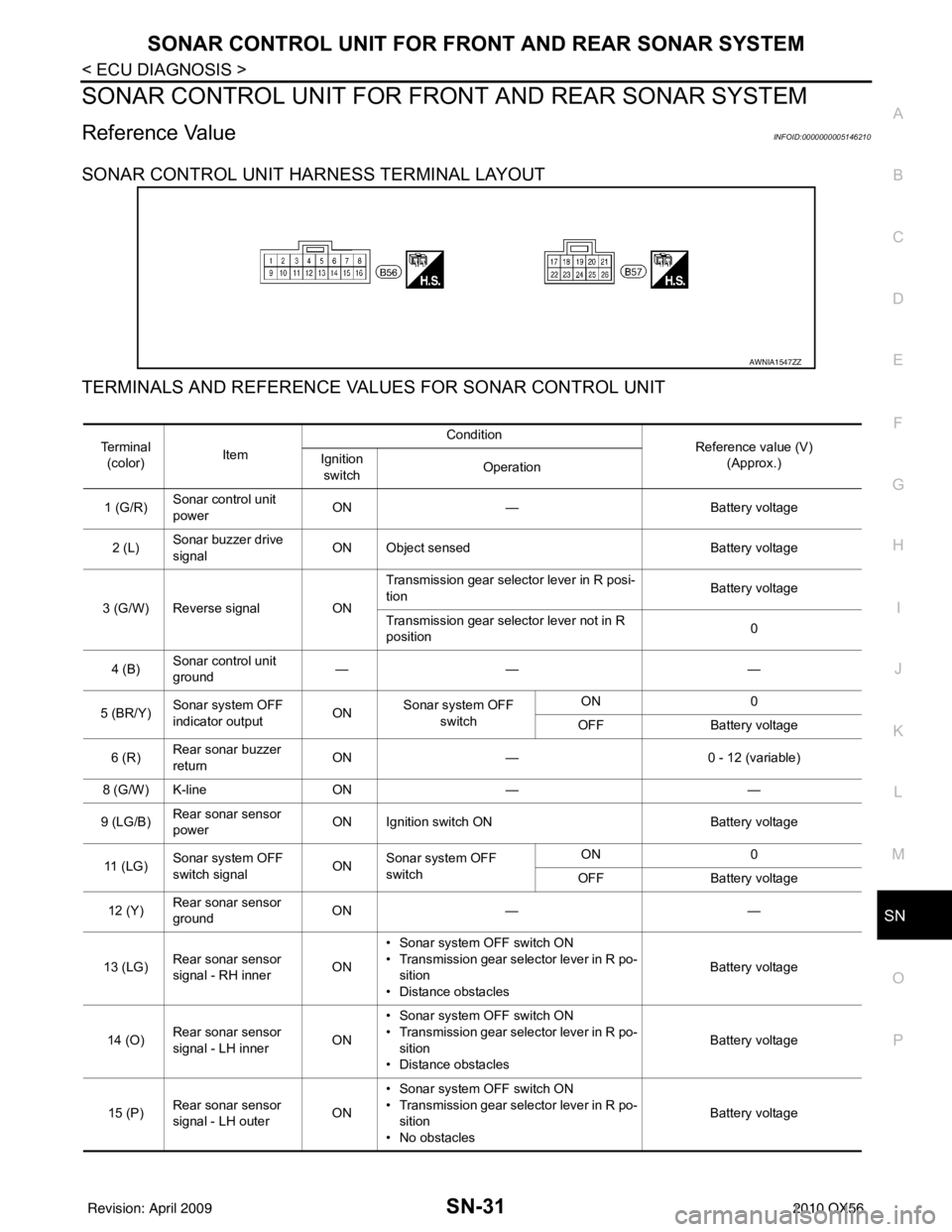
SONAR CONTROL UNIT HARNESS TERMINAL LAYOUT
TERMINALS AND REFERENCE VA LUES FOR SONAR CONTROL UNIT
AWNIA1547ZZ
Te r m i n a l
(color) Item Condition
Reference value (V)
(Approx.)
Ignition
switch Operation
1 (G/R) Sonar control unit
power ON
— Battery voltage
2 (L) Sonar buzzer drive
signal
ON Object sensed
Battery voltage
3 (G/W) Reverse signal ONTransmission gear selector lever in R posi-
tion
Battery voltage
Transmission gear selector lever not in R
position 0
4 (B) Sonar control unit
ground ——
—
5 (BR/Y) Sonar system OFF
indicator output ON
Sonar system OFF
switch ON
0
OFF Battery voltage
6 (R) Rear sonar buzzer
return
ON
— 0 - 12 (variable)
8 (G/W) K-line ON— —
9 (LG/B) Rear sonar sensor
power ON Ignition switch ON
Battery voltage
11 ( L G ) Sonar system OFF
switch signal
ONSonar system OFF
switch ON
0
OFF Battery voltage
12 (Y) Rear sonar sensor
ground ON
— —
13 (LG) Rear sonar sensor
signal - RH inner ON• Sonar system OFF switch ON
• Transmission gear selector lever in R po-
sition
• Distance obstacles Battery voltage
14 (O) Rear sonar sensor
signal - LH inner ON• Sonar system OFF switch ON
• Transmission gear selector lever in R po-
sition
• Distance obstacles Battery voltage
15 (P) Rear sonar sensor
signal - LH outer ON• Sonar system OFF switch ON
• Transmission gear selector lever in R po-
sition
• No obstacles Battery voltage
Revision: April 20092010 QX56
Page 3504 of 4210
SN-32
< ECU DIAGNOSIS >
SONAR CONTROL UNIT FOR FRONT AND REAR SONAR SYSTEM
16 (GR)Rear sonar sensor
signal - RH outer ON• Sonar system OFF switch ON
• Transmission gear selector lever in R po-
sition
• No obstacles Battery voltage
17 (LG/B) Front sonar sensor
power
ON Ignition switch ON
Battery voltage
18 (GR/R) Park position signal ON Vehicle in PARK 12
19 (GR) Front sonar sensor
signal - RH outer ON• Sonar system OFF switch ON
• Transmission gear selector lever in a for-
ward drive gear
• Distance obstacles Battery voltage
20 (LG) Front sonar sensor
signal - RH inner ON• Sonar system OFF switch ON
• Transmission gear selector lever in re-
verse or a forward drive gear
• No obstacles Battery voltage
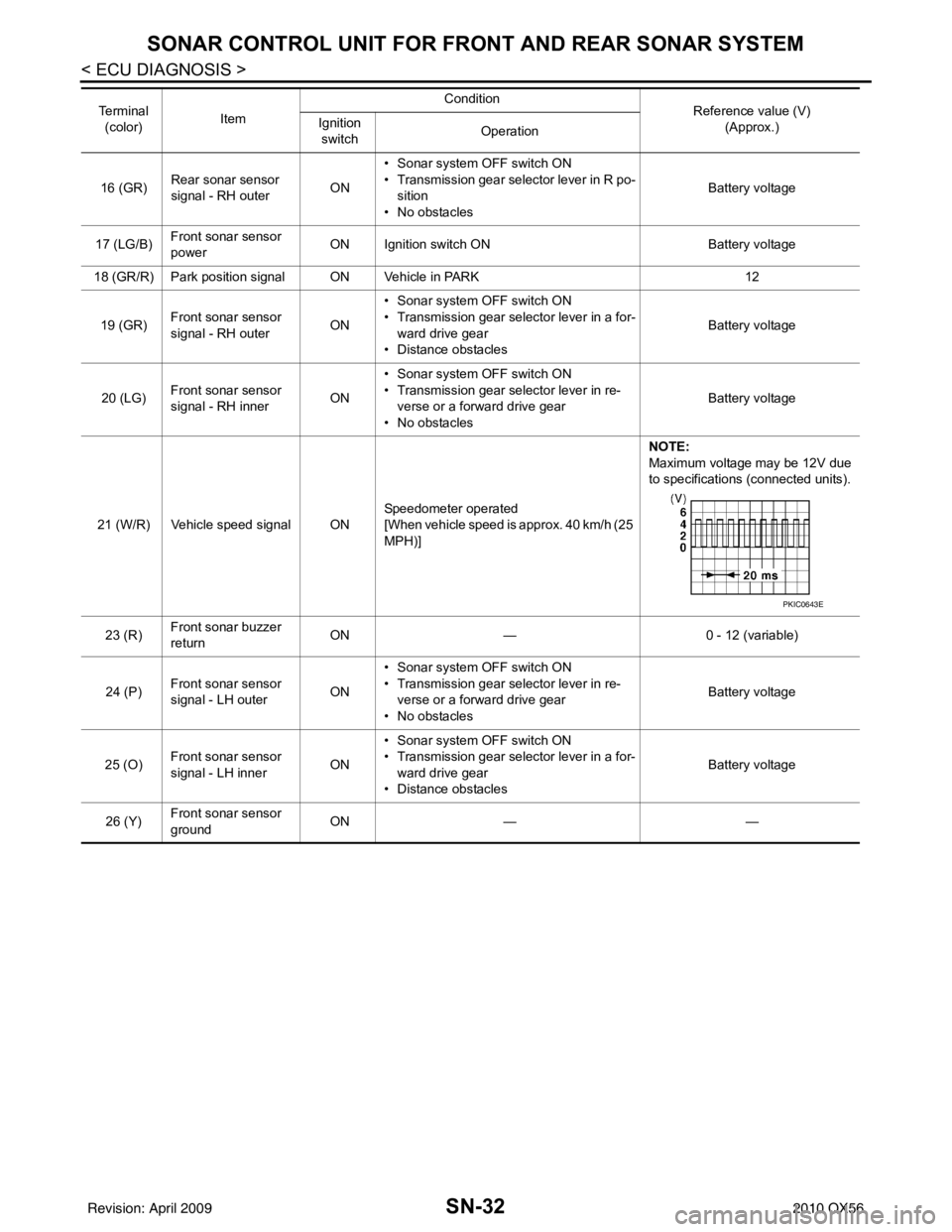
21 (W/R) Vehicle speed signal ON Speedometer operated
[When vehicle speed is approx. 40 km/h (25
MPH)]NOTE:
Maximum voltage may be 12V due
to specifications (connected units).
23 (R) Front sonar buzzer
return ON
— 0 - 12 (variable)
24 (P) Front sonar sensor
signal - LH outer
ON• Sonar system OFF switch ON
• Transmission gear selector lever in re-
verse or a forward drive gear
• No obstacles Battery voltage
25 (O) Front sonar sensor
signal - LH inner
ON• Sonar system OFF switch ON
• Transmission gear selector lever in a for-
ward drive gear
• Distance obstacles Battery voltage
26 (Y) Front sonar sensor
ground ON
— —
Te r m i n a l
(color) Item Condition
Reference value (V)
(Approx.)
Ignition
switch Operation
PKIC0643E
Revision: April 20092010 QX56
Page 3517 of 4210

SN
SONAR SYSTEM SYMPTOMSSN-45
< SYMPTOM DIAGNOSIS >
C
DE
F
G H
I
J
K L
M B A
O P
SYMPTOM DIAGNOSIS
SONAR SYSTEM SYMPTOMS
Symptom TableINFOID:0000000005146213
Symptom Repair order
When the sonar system is OFF, the OFF indicator does not light
and the sonar buzzer does not sound. 1. Check sonar system OFF switch. Refer to
SN-20, "
Compo-
nent Inspection" or SN-19, "Diagnosis Procedure (With
Front and Rear Sonar System)".
2. Check harness and connections for sonar system OFF
switch.
3. Replace sonar control unit. Refer to SN-50, "
Removal and
Installation".
When the sonar system is OFF, the OFF indicator lamp does not
light but the sonar buzzer does sound. 1. Check sonar system OFF switch. Refer to
SN-19, "
Diagno-
sis Procedure (With Rear Sonar System)" or SN-19, "Diag-
nosis Procedure (With Front and Rear Sonar System)".
2. Check harness and connections for sonar system OFF indi- cator lamp.
3. Replace sonar control unit.
When the sonar system is OFF, the sonar buzzer does not sound
but the OFF indicator lamp lights. 1. Check sonar buzzer. Refer to
SN-18, "
Component Inspec-
tion" or SN-17, "Diagnosis Procedure (With Front and Rear
Sonar System)".
2. Check harness and connections between sonar buzzer and sonar control unit.
3. Replace sonar control unit.
When sonar system is ON, the sonar system OFF indicator lamp
lights up and the sonar buzzer sounds intermittently (for about 4
seconds). (Rear sonar system only) 1. Check harnesses between sonar sensors and sonar control
unit for an open condition.
2. Check sonar sensors. Refer to SN-5, "
Preliminary Check".
3. Replace sonar control unit.
The sonar system still operates when the sonar system is OFF. 1. Replace sonar control unit.
When the transmission gear selector lever is in the R position and
the sonar system is ON, the rear sonar system does not operate. 1. Check transmissin range switch. Refer to
TM-45, "
Diagnosis
Procedure".
2. Check back-up lamp relay.
3. Check related harness and connections for back-up lamp re- lay.
4. Replace sonar control unit.
When the transmission gear selector lever is in a forward drive
gear and the sonar system is ON, the front sonar system does not
operate. (With front and rear sonar system only) 1. Check harness and connections between sonar control unit
and combination meter.
2. Replace sonar control unit.
Sonar system OFF indicator lamp lights up and buzzer sounds al-
though there are no obstacles within the detection range. 1. Check sonar sensors.
2. Check harness and connections between sonar sensors
and sonar control unit.
3. Replace sonar control unit.
The sonar sensors do not detect objects in the detectable range. 1. Check sonar sensors.
2. Replace sonar control unit.
Revision: April 20092010 QX56
Page 3685 of 4210
STR-10
< COMPONENT DIAGNOSIS >
B TERMINAL CIRCUIT
COMPONENT DIAGNOSIS
B TERMINAL CIRCUIT
DescriptionINFOID:0000000005149554
Terminal "2" (B) is constantly supplied with battery power.
Diagnosis ProcedureINFOID:0000000005149555
Regarding Wiring Diagram information, refer to STR-14, "Wiring Diagram".
CAUTION:
Perform diagnosis under the condi tion that the engine cannot start by the following procedure.
1. Remove fuel pump fuse.
2. Crank or start the engine (where possible) until the fuel pressure is depleted.
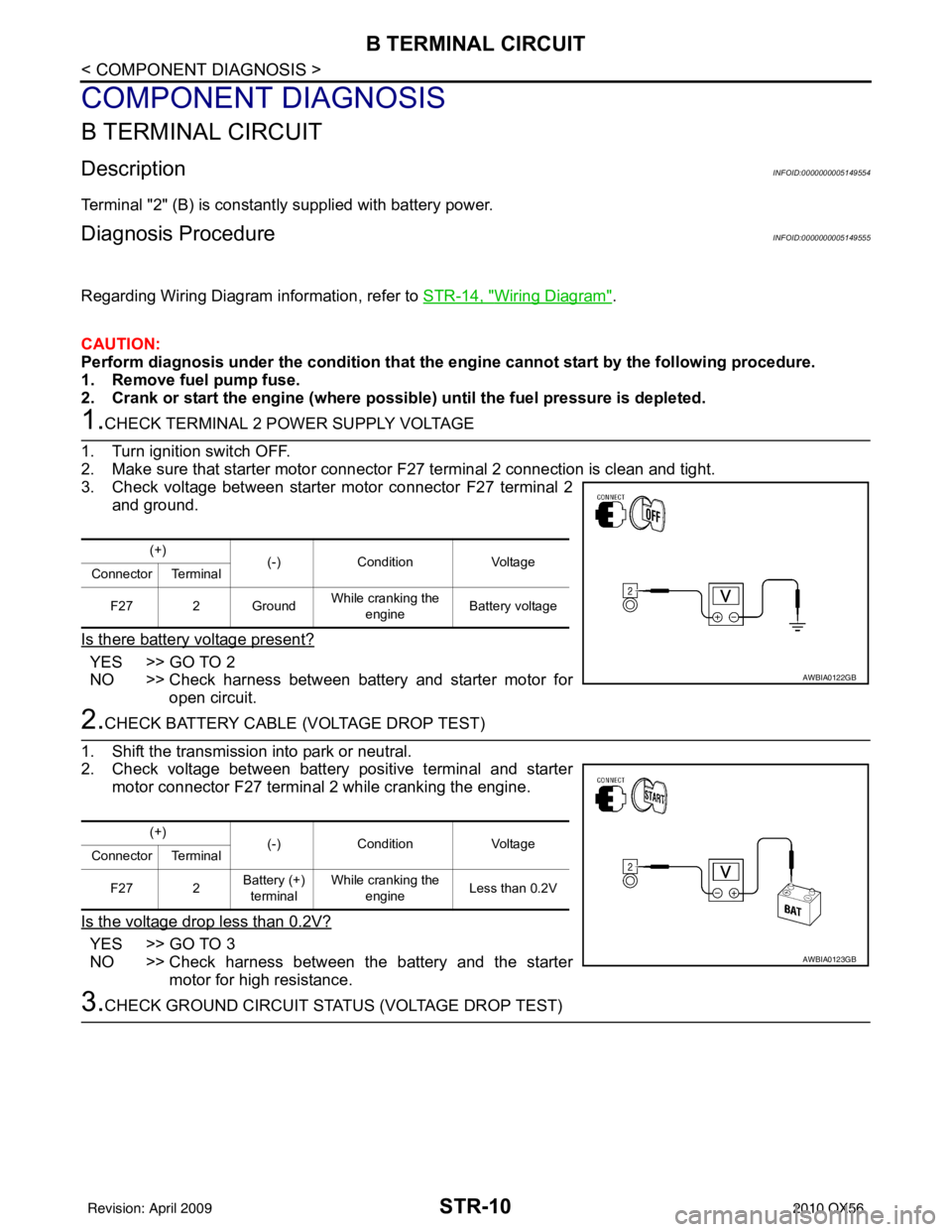
1.CHECK TERMINAL 2 POWER SUPPLY VOLTAGE
1. Turn ignition switch OFF.
2. Make sure that starter motor connector F27 terminal 2 connection is clean and tight.
3. Check voltage between starter motor connector F27 terminal 2
and ground.
Is there battery voltage present?
YES >> GO TO 2
NO >> Check harness between battery and starter motor for open circuit.
2.CHECK BATTERY CABLE (VOLTAGE DROP TEST)
1. Shift the transmission into park or neutral.
2. Check voltage between battery positive terminal and starter motor connector F27 terminal 2 while cranking the engine.
Is the voltage drop less than 0.2V?
YES >> GO TO 3
NO >> Check harness between the battery and the starter motor for high resistance.
3.CHECK GROUND CIRCUIT STATUS (VOLTAGE DROP TEST)
(+) (-)Condition Voltage
Connector Terminal
F27 2 Ground While cranking the
engine Battery voltage
AWBIA0122GB
(+)
(-)Condition Voltage
Connector Terminal
F27 2 Battery (+)
terminal While cranking the
engine Less than 0.2V
AWBIA0123GB
Revision: April 20092010 QX56
Page 3687 of 4210
STR-12
< COMPONENT DIAGNOSIS >
S CONNECTOR CIRCUIT
S CONNECTOR CIRCUIT
DescriptionINFOID:0000000005149556
Terminal "1" (S) is the power supply for the starter motor magnetic switch. Terminal 1 is supplied with power
when the ignition switch is turned to the START position while the selector lever is in the P or N position.
Diagnosis ProcedureINFOID:0000000005149557
Regarding Wiring Diagram information, refer to STR-14, "Wiring Diagram".
CAUTION:
Perform diagnosis under the condi tion that engine cannot start by the following procedure.
1. Remove fuel pump fuse.
2. Crank or start the engine (where possi ble) until the fuel pressure is released.
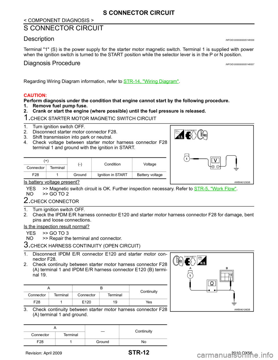
1.CHECK STARTER MOTOR MAGNETIC SWITCH CIRCUIT
1. Turn ignition switch OFF.
2. Disconnect starter motor connector F28.
3. Shift transmission into park or neutral.
4. Check voltage between starter motor harness connector F28 terminal 1 and ground with the ignition in START.
Is battery voltage present?
YES >> Magnetic switch circuit is OK. Further inspection necessary. Refer to STR-5, "Work Flow".
NO >> GO TO 2
2.CHECK CONNECTOR
1. Turn ignition switch OFF.
2. Check the IPDM E/R harness connector E120 and st arter motor harness connector F28 for damage, bent
pins and loose connections.
Is the inspection result normal?
YES >> GO TO 3
NO >> Repair the terminal and connector.
3.CHECK HARNESS CONTI NUITY (OPEN CIRCUIT)
1. Disconnect IPDM E/R connector E120 and starter motor con- nector F28.
2. Check continuity between starter motor harness connector F28
(A) terminal 1 and IPDM E/R harness connector E120 (B) termi-
nal 19.
3. Check continuity between starter motor harness connector F28 (A) terminal 1 and ground.
(+) (-)Condition Voltage
Connector Terminal
F28 1 Ground Ignition in START Battery voltage
AWBIA0125GB
AB Continuity
Connector Terminal Connector Terminal
F28 1E120 19 Yes
A —Contin u it y
Connector Terminal
F28 1Ground No
AWBIA0126GB
Revision: April 20092010 QX56
Page 3696 of 4210
TM-1
TRANSMISSION & DRIVELINE
CEF
G H
I
J
K L
M
SECTION TM
A
B
TM
N
O P
CONTENTS
TRANSAXLE & TRANSMISSION
BASIC INSPECTION ....... .............................5
DIAGNOSIS AND REPAIR WORKFLOW ..... .....5
Work Flow ........................................................... ......5
Diagnostic Work Sheet ..............................................6
FUNCTION DIAGNOSIS ...............................8
A/T CONTROL SYSTEM ................................ .....8
Cross-Sectional View (2WD models) .................. ......8
Cross-Sectional View (4WD models) ........................9
Shift Mechanism ........................................................9
TCM Function ..........................................................20
CAN Communication ...............................................21
Input/Output Signal of TCM .....................................22
Line Pressure Control .............................................22
Shift Control ........................................................ ....24
Lock-up Control .......................................................25
Engine Brake Control ..............................................26
Control Valve ...........................................................26
Component Parts Location ......................................28
A/T SHIFT LOCK SYSTEM ............................ ....29
System Description ............................................. ....29
Component Parts Location ......................................29
ON BOARD DIAGNOSTIC (OBD) SYSTEM ......30
Introduction ......................................................... ....30
OBD-II Function for A/T System ..............................30
One or Two Trip Detection Logic of OBD-II ............30
OBD-II Diagnostic Trouble Code (DTC) ..................30
Malfunction Indicator Lamp (MIL) ............................31
DIAGNOSIS SYSTEM (TCM) .............................32
CONSULT-III Function (TRANSMISSION) ......... ....32
Diagnosis Procedure without CONSULT-III ........ ....37
COMPONENT DIAGNOSIS .........................40
U1000 CAN COMM CI RCUIT .............................40
Description .......................................................... ....40
On Board Diagnosis Logic ......................................40
Possible Cause .................................................... ....40
DTC Confirmation Procedure ..................................40
Diagnosis Procedure ...............................................40
P0615 STARTER RELAY .................................41
Description ...............................................................41
CONSULT-III Reference Value in Data Monitor
Mode .................................................................... ....
41
On Board Diagnosis Logic .......................................41
Possible Cause ........................................................41
DTC Confirmation Procedure ..................................41
Diagnosis Procedure ...............................................41
P0700 TRANSMISSION CONTROL .................44
Description ...............................................................44
On Board Diagnosis Logic .......................................44
Possible Cause ........................................................44
DTC Confirmation Procedure ..................................44
Diagnosis Procedure ...............................................44
P0705 TRANSMISSION RANGE SWITCH A ...45
Description ...............................................................45
CONSULT-III Reference Value in Data Monitor
Mode .................................................................... ....
45
On Board Diagnosis Logic .......................................45
Possible Cause ........................................................45
DTC Confirmation Procedure ..................................45
Diagnosis Procedure ...............................................45
P0717 INPUT SPEED SENSOR A ....................48
Description ...............................................................48
CONSULT-III Reference Value in Data Monitor
Mode .................................................................... ....
48
On Board Diagnosis Logic .......................................48
Possible Cause ........................................................48
DTC Confirmation Procedure ..................................48
Diagnosis Procedure ...............................................48
P0720 OUTPUT SPEED SENSOR ...................50
Description ...............................................................50
CONSULT-III Reference Value in Data Monitor
Mode .................................................................... ....
50
Revision: April 20092010 QX56
Page 3697 of 4210

TM-2
On Board Diagnosis Logic ......................................50
Possible Cause .......................................................50
DTC Confirmation Procedure .................................50
Diagnosis Procedure ..............................................51
P0725 ENGINE SPEED .....................................53
Description ........................................................... ...53
CONSULT-III Reference Value in Data Monitor
Mode .................................................................... ...
53
On Board Diagnosis Logic ......................................53
Possible Cause .......................................................53
DTC Confirmation Procedure .................................53
Diagnosis Procedure ..............................................53
P0731 1GR INCORRECT RATIO ......................55
Description ........................................................... ...55
On Board Diagnosis Logic ......................................55
Possible Cause .......................................................55
DTC Confirmation Procedure .................................55
Diagnosis Procedure ..............................................56
P0732 2GR INCORRECT RATIO ......................57
Description ........................................................... ...57
On Board Diagnosis Logic ......................................57
Possible Cause .......................................................57
DTC Confirmation Procedure .................................57
Diagnosis Procedure ..............................................58
P0733 3GR INCORRECT RATIO ......................59
Description ........................................................... ...59
On Board Diagnosis Logic ......................................59
Possible Cause .......................................................59
DTC Confirmation Procedure .................................59
Diagnosis Procedure ..............................................60
P0734 4GR INCORRECT RATIO ......................61
Description ........................................................... ...61
On Board Diagnosis Logic ......................................61
Possible Cause .......................................................61
DTC Confirmation Procedure .................................61
Diagnosis Procedure ..............................................62
P0735 5GR INCORRECT RATIO ......................63
Description ........................................................... ...63
On Board Diagnosis Logic ......................................63
Possible Cause .......................................................63
DTC Confirmation Procedure .................................63
Diagnosis Procedure ..............................................64
P0740 TORQUE CONVERTER .........................65
Description ........................................................... ...65
CONSULT-III Reference Value in Data Monitor
Mode .................................................................... ...
65
On Board Diagnosis Logic ......................................65
Possible Cause .......................................................65
DTC Confirmation Procedure .................................65
Diagnosis Procedure ..............................................65
P0744 TORQUE CONVERTER .........................67
Description ........................................................... ...67
CONSULT-III Reference Value in Data Monitor
Mode .................................................................... ...
67
On Board Diagnosis Logic ......................................67
Possible Cause .......................................................67
DTC Confirmation Procedure ..................................67
Diagnosis Procedure ...............................................68
P0745 PRESSURE CONTROL SOLENOID A ...69
Description ........................................................... ...69
CONSULT-III Reference Value in Data Monitor
Mode .................................................................... ...
69
On Board Diagnosis Logic ......................................69
Possible Cause .......................................................69
DTC Confirmation Procedure ..................................69
Diagnosis Procedure ...............................................69
P1705 TP SENSOR ...........................................71
Description ..............................................................71
CONSULT-III Reference Value in Data Monitor
Mode .................................................................... ...
71
On Board Diagnosis Logic ......................................71
Possible Cause .......................................................71
DTC Confirmation Procedure ..................................71
Diagnosis Procedure ...............................................71
P1710 TRANSMISSION FLUID TEMPERA-
TURE SENSOR .................................................
73
Description ........................................................... ...73
CONSULT-III Reference Value in Data Monitor
Mode .................................................................... ...
73
On Board Diagnosis Logic ......................................73
Possible Cause .......................................................73
DTC Confirmation Procedure ..................................73
Diagnosis Procedure ...............................................73
Component Inspection ............................................74
P1721 VEHICLE SPEED SIGNAL ....................76
Description ..............................................................76
CONSULT-III Reference Value in Data Monitor
Mode .................................................................... ...
76
On Board Diagnosis Logic ......................................76
Possible Cause .......................................................76
DTC Confirmation Procedure ..................................76
Diagnosis Procedure ...............................................76
P1730 INTERLOCK ...........................................78
Description ..............................................................78
On Board Diagnosis Logic ......................................78
Possible Cause .......................................................78
DTC Confirmation Procedure ..................................78
Judgment of Interlock ..............................................78
Diagnosis Procedure ...............................................78
P1731 1ST ENGINE BRAKING .........................80
Description ........................................................... ...80
CONSULT-III Reference Value in Data Monitor
Mode .................................................................... ...
80
On Board Diagnosis Logic ......................................80
Possible Cause .......................................................80
DTC Confirmation Procedure ..................................80
Revision: April 20092010 QX56
Page 3699 of 4210

TM-4
STALL TEST ....................................................155
Inspection and Judgment .................................... ..155
LINE PRESSURE TEST ..................................157
Inspection and Judgment .................................... ..157
ROAD TEST .....................................................159
Description ........................................................... ..159
Check Before Engine Is Started ............................159
Check At Idle ....................................................... ..159
Cruise Test - Part 1 ...............................................160
Cruise Test - Part 2 ...............................................162
Cruise Test - Part 3 ...............................................162
Vehicle Speed When Shifting Gears .....................163
Vehicle Speed When Performing and Releasing
Complete Lock-up .................................................
163
A/T POSITION .................................................164
Adjustment of A/T Position .................................. ..164
Checking of A/T Position .......................................164
ON-VEHICLE REPAIR ...............................165
SHIFT CONTROL SYSTEM ........................... .165
A/T Shift Selector Removal and Installation ..........165
AIR BREATHER HOSE .................................. .166
Removal and Installation ..................................... ..166
OIL PAN ...........................................................170
Oil Pan ................................................................. ..170
CONTROL VALVE WITH TCM ........................172
Control Valve with TCM and A/T Fluid Tempera-
ture Sensor 2 and Plug ........................................ ..
172
REAR OIL SEAL ..............................................184
Rear Oil Seal ....................................................... ..184
FLUID COOLER SYSTEM ...............................185
Exploded View ..................................................... ..185
Removal and Installation .......................................185
REMOVAL AND INSTALLATION ..............186
TRANSMISSION ASSEMBLY ........................ .186
Removal and Installation (2WD) .......................... .186
Removal and Installation (4WD) ...........................188
DISASSEMBLY AND ASSEMBLY ...........192
OVERHAUL ......................................................192
Component .......................................................... .192
Oil Channel ...........................................................199
Location of Adjusting Shims, Needle Bearings,
Thrust Washers and Snap Rings ......................... .
201
DISASSEMBLY .............................................. ..204
Disassembly ......................................................... .204
REPAIR FOR COMPONENT PARTS ..............223
Oil Pump .............................................................. .223
Front Sun Gear, 3rd One-Way Clutch ...................225
Front Carrier, Input Clutch, Rear Internal Gear .....227
Mid Sun Gear, Rear Sun Gear, High and Low Re-
verse Clutch Hub ................................................. .
232
High and Low Reverse Clutch ..............................237
Direct Clutch .........................................................239
ASSEMBLY .................................................... ..242
Assembly (1) ........................................................ .242
Adjustment ............................................................255
Assembly (2) .........................................................257
SERVICE DATA AND SPECIFICATIONS
(SDS) ........ .................................................
265
SERVICE DATA AND SPECIFICATIONS
(SDS) .............................................................. ..
265
General Specification ........................................... .265
Vehicle Speed at Which Gear Shifting Occurs .....265
Vehicle Speed at Which Lock-up Occurs/Releas-
es ......................................................................... .
266
Stall Speed ............................................................266
Line Pressure ........................................................266
Input Speed Sensor ..............................................266
Output Speed Sensor ...........................................266
Reverse Brake ......................................................266
Total End Play .......................................................267
Torque Converter ..................................................267
Revision: April 20092010 QX56