Page 3268 of 4210
SCS-36
< SYMPTOM DIAGNOSIS >
SUSPENSION CONTROL SYSTEM
SYMPTOM DIAGNOSIS
SUSPENSION CONTROL SYSTEM
Symptom TableINFOID:0000000005148193
AIR LEVELIZER
SymptomPossible causeReference page
Inoperative • Suspension control unit
• Compressor motor relay
• Suspension air compressorSCS-37, "
Diagnosis Proce-
dure"
System does not raise • Suspension control unit
• Height sensor
• Compressor motor relay
• Suspension air compressor
• Leak in system
• Restriction in systemSCS-38, "Diagnosis Proce-
dure"
System does not lower
• Suspension control unit
• Height sensor
• Compressor motor relay
• Suspension air compressor
• Restriction in systemSCS-39, "Diagnosis Proce-
dure"
CK SUSP indicator lamp always ON with key ON
• CK SUSP indicator la
mp control circuit
• Suspension control unit SCS-26, "Description"
Revision: April 20092010 QX56
Page 3269 of 4210

SUSPENSION CONTROL SYSTEM INOPERATIVESCS-37
< SYMPTOM DIAGNOSIS >
C
DF
G H
I
J
K L
M A
B
SCS
N
O P
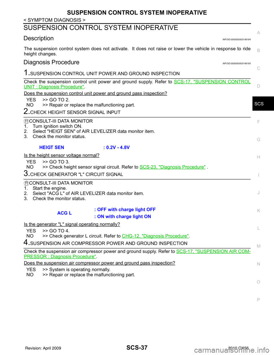
SUSPENSION CONTROL SYSTEM INOPERATIVE
DescriptionINFOID:0000000005148194
The suspension control system does not activate. It does not raise or lower the vehicle in response to ride
height changes.
Diagnosis ProcedureINFOID:0000000005148195
1.SUSPENSION CONTROL UNIT PO WER AND GROUND INSPECTION
Check the suspension control unit power and ground supply. Refer to SCS-17, "
SUSPENSION CONTROL
UNIT : Diagnosis Procedure".
Does the suspension control uni t power and ground pass inspection?
YES >> GO TO 2.
NO >> Repair or replace the malfunctioning part.
2.CHECK HEIGHT SENSOR SIGNAL INPUT
CONSULT-III DATA MONITOR
1. Turn ignition switch ON.
2. Select "HEIGT SEN" of AI R LEVELIZER data monitor item.
3. Check the monitor status.
Is the height sensor voltage normal?
YES >> GO TO 3.
NO >> Check height sensor signal circuit. Refer to SCS-23, "
Diagnosis Procedure" .
3.CHECK GENERATOR "L" CIRCUIT SIGNAL
CONSULT-III DATA MONITOR
1. Start the engine.
2. Select "ACG L" of AIR LEVELIZER data monitor item.
3. Check the monitor status.
Is the generator "L" signal operating normally?
YES >> GO TO 4.
NO >> Check generator L circuit. Refer to CHG-12, "
Diagnosis Procedure".
4.SUSPENSION AIR COMPRESSOR POWER AND GROUND INSPECTION
Check the suspension air compressor power and ground supply. Refer to SCS-17, "
SUSPENSION AIR COM-
PRESSOR : Diagnosis Procedure".
Does the suspension air compress or power and ground pass inspection?
YES >> System is operating normally.
NO >> Repair or replace the malfunctioning part.HEIGT SEN : 0.2V - 4.8V
ACG L
: OFF with charge light OFF
: ON with charge light ON
Revision: April 20092010 QX56
Page 3270 of 4210

SCS-38
< SYMPTOM DIAGNOSIS >
SUSPENSION CONTROL SYSTEM DOES NOT RAISE
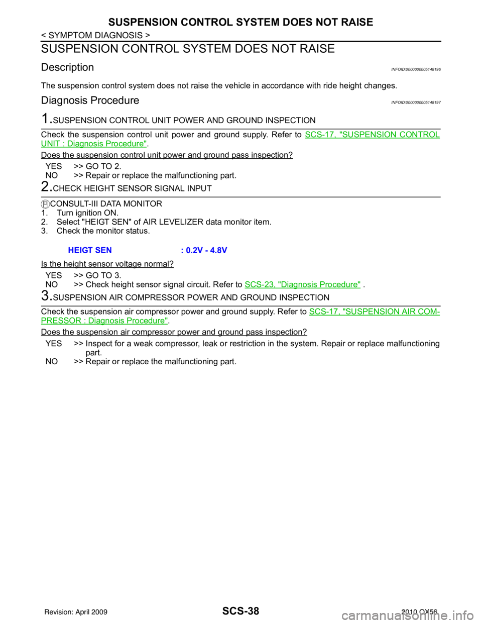
SUSPENSION CONTROL SYSTEM DOES NOT RAISE
DescriptionINFOID:0000000005148196
The suspension control system does not raise t he vehicle in accordance with ride height changes.
Diagnosis ProcedureINFOID:0000000005148197
1.SUSPENSION CONTROL UNIT POWER AND GROUND INSPECTION
Check the suspension control unit power and ground supply. Refer to SCS-17, "
SUSPENSION CONTROL
UNIT : Diagnosis Procedure".
Does the suspension control unit power and ground pass inspection?
YES >> GO TO 2.
NO >> Repair or replace the malfunctioning part.
2.CHECK HEIGHT SENSOR SIGNAL INPUT
CONSULT-III DATA MONITOR
1. Turn ignition ON.
2. Select "HEIGT SEN" of AI R LEVELIZER data monitor item.
3. Check the monitor status.
Is the height sensor voltage normal?
YES >> GO TO 3.
NO >> Check height sensor signal circuit. Refer to SCS-23, "
Diagnosis Procedure" .
3.SUSPENSION AIR COMPRESSOR POWER AND GROUND INSPECTION
Check the suspension air compressor power and ground supply. Refer to SCS-17, "
SUSPENSION AIR COM-
PRESSOR : Diagnosis Procedure".
Does the suspension air compressor power and ground pass inspection?
YES >> Inspect for a weak compressor, leak or restri ction in the system. Repair or replace malfunctioning
part.
NO >> Repair or replace the malfunctioning part. HEIGT SEN
: 0.2V - 4.8V
Revision: April 20092010 QX56
Page 3271 of 4210

SUSPENSION CONTROL SYSTEM DOES NOT LOWER
SCS-39
< SYMPTOM DIAGNOSIS >
C
D F
G H
I
J
K L
M A
B
SCS
N
O P
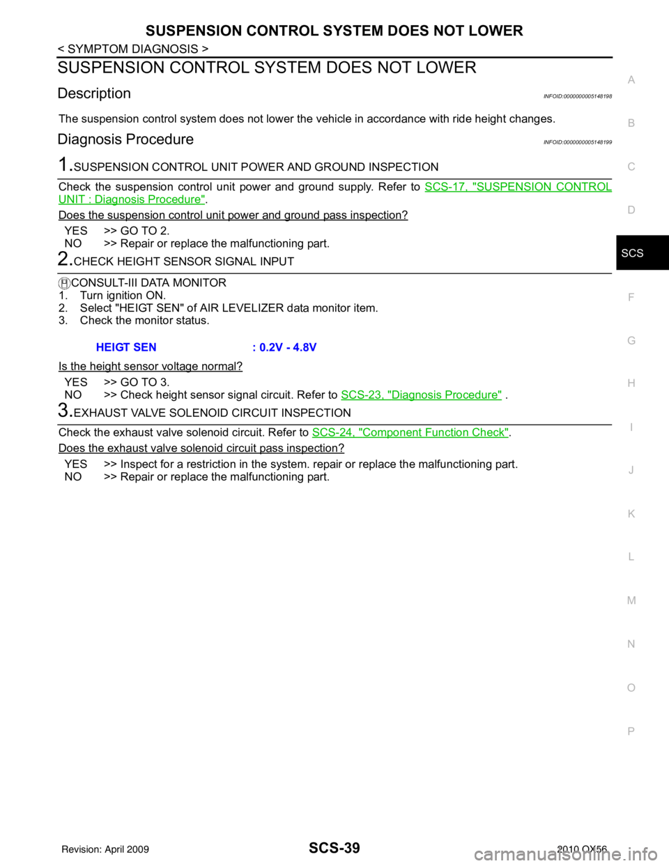
SUSPENSION CONTROL SYST EM DOES NOT LOWER
DescriptionINFOID:0000000005148198
The suspension control system does not lower the vehicle in accordance with ride height changes.
Diagnosis ProcedureINFOID:0000000005148199
1.SUSPENSION CONTROL UNIT POWER AND GROUND INSPECTION
Check the suspension control unit power and ground supply. Refer to SCS-17, "
SUSPENSION CONTROL
UNIT : Diagnosis Procedure".
Does the suspension control uni t power and ground pass inspection?
YES >> GO TO 2.
NO >> Repair or replace the malfunctioning part.
2.CHECK HEIGHT SENSOR SIGNAL INPUT
CONSULT-III DATA MONITOR
1. Turn ignition ON.
2. Select "HEIGT SEN" of AI R LEVELIZER data monitor item.
3. Check the monitor status.
Is the height sensor voltage normal?
YES >> GO TO 3.
NO >> Check height sensor signal circuit. Refer to SCS-23, "
Diagnosis Procedure" .
3.EXHAUST VALVE SOLENOID CIRCUIT INSPECTION
Check the exhaust valve solenoid circuit. Refer to SCS-24, "
Component Function Check".
Does the exhaust valve solenoi d circuit pass inspection?
YES >> Inspect for a restriction in the system. repair or replace the malfunctioning part.
NO >> Repair or replace the malfunctioning part.HEIGT SEN : 0.2V - 4.8V
Revision: April 20092010 QX56
Page 3869 of 4210
TM-174
< ON-VEHICLE REPAIR >
CONTROL VALVE WITH TCM
10. Remove bolts (A), (B) and (C) from control valve with TCM.• : Front
11. Remove control valve with TCM from transmission case. CAUTION:
When removing, be careful with the manual valve notch and
manual plate height. Remove it vertically.
12. Remove the A/T fluid temperature sensor 2 or plug as shown below.
a. A/T fluid temperature sensor 2
i. Remove A/T fluid temperature sensor 2 with bracket from con- trol valve with TCM.
ii. Remove bracket from A/T fluid temperature sensor 2.
b. Plug
Bolt symbol Length mm (in) Number of bolts
A 42 (1.65) 5
B 55 (2.17) 6
C 40 (1.57) 1
SCIA8074E
SCIA5142E
SCIA5253E
SCIA5264E
Revision: April 20092010 QX56
Page 3906 of 4210
DISASSEMBLYTM-211
< DISASSEMBLY AND ASSEMBLY >
CEF
G H
I
J
K L
M A
B
TM
N
O P
32. Disconnect output speed sensor connector (1). CAUTION:
Do not damage connector.
33. Straighten terminal clip ( ) to free output speed sensor har- ness.
34. Remove bolts (A), (B) and (C) from control valve with TCM. • : Front
35. Remove control valve with TCM from transmission case. CAUTION:
When removing, be careful with the manual valve notch and
manual plate height. Remove it vertically.
36. Remove the A/T fluid temperature sensor 2 or plug as shown below.
a. A/T fluid temperature sensor 2
JSDIA1319ZZ
JSDIA1320ZZ
Bolt symbol Length mm (in) Number of bolts
A 42 (1.65) 5
B 55 (2.17) 6
C 40 (1.57) 1
SCIA8077E
SCIA5260E
Revision: April 20092010 QX56