2010 INFINITI QX56 engine oil
[x] Cancel search: engine oilPage 1945 of 4210
EM-94
< DISASSEMBLY AND ASSEMBLY >
ENGINE UNIT
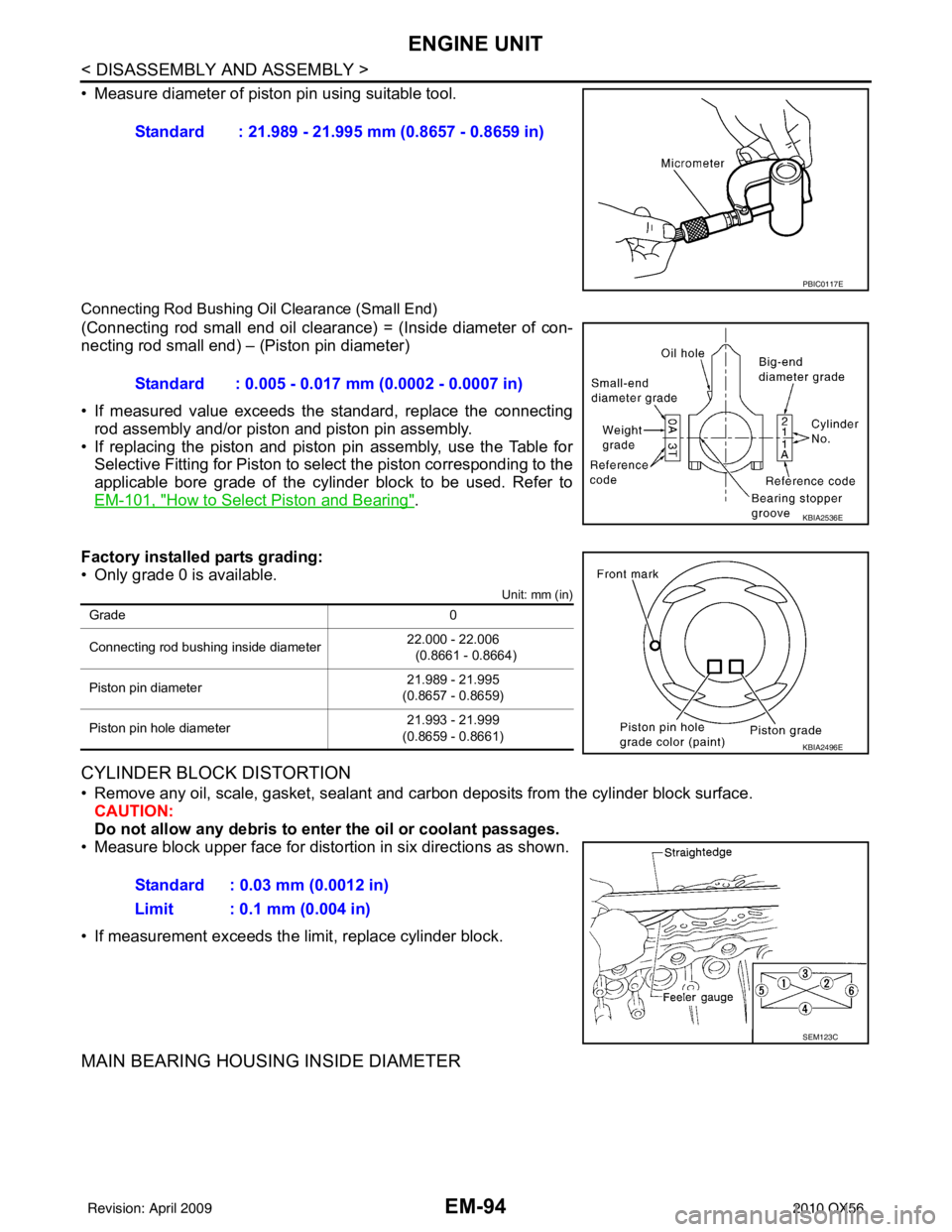
• Measure diameter of piston pin using suitable tool.
Connecting Rod Bushing Oil Clearance (Small End)
(Connecting rod small end oil clearance) = (Inside diameter of con-
necting rod small end) – (Piston pin diameter)
• If measured value exceeds the standard, replace the connectingrod assembly and/or piston and piston pin assembly.
• If replacing the piston and piston pin assembly, use the Table for
Selective Fitting for Piston to select the piston corresponding to the
applicable bore grade of the cylinder block to be used. Refer to
EM-101, "
How to Select Piston and Bearing".
Factory installed parts grading:
• Only grade 0 is available.
Unit: mm (in)
CYLINDER BLOCK DISTORTION
• Remove any oil, scale, gasket, sealant and carbon deposits from the cylinder block surface.
CAUTION:
Do not allow any debris to en ter the oil or coolant passages.
• Measure block upper face for distortion in six directions as shown.
• If measurement exceeds the limit, replace cylinder block.
MAIN BEARING HOUSING INSIDE DIAMETER
Standard : 21.989 - 21.995 mm (0.8657 - 0.8659 in)
PBIC0117E
Standard : 0.005 - 0.017 mm (0.0002 - 0.0007 in)
KBIA2536E
Grade 0
Connecting rod bushing inside diameter 22.000 - 22.006
(0.8661 - 0.8664)
Piston pin diameter 21.989 - 21.995
(0.8657 - 0.8659)
Piston pin hole diameter 21.993 - 21.999
(0.8659 - 0.8661)
KBIA2496E
Standard : 0.03 mm (0.0012 in)
Limit : 0.1 mm (0.004 in)
SEM123C
Revision: April 20092010 QX56
Page 1947 of 4210
EM-96
< DISASSEMBLY AND ASSEMBLY >
ENGINE UNIT
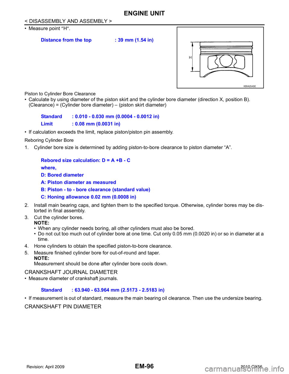
• Measure point ″H″.
Piston to Cylinde r Bore Clearance
• Calculate by using diameter of the piston skirt and the cylinder bore diameter (direction X, position B).
(Clearance) = (Cylinder bore diameter) – (piston skirt diameter)
• If calculation exceeds the limit, replace piston/piston pin assembly.
Reboring Cylinder Bore
1. Cylinder bore size is determined by adding pi ston-to-bore clearance to piston diameter “A”.
2. Install main bearing caps, and tighten them to the specified torque. Otherwise, cylinder bores may be dis-
torted in final assembly.
3. Cut the cylinder bores. NOTE:
• When any cylinder needs boring, all other cylinders must also be bored.
• Do not cut too much out of cylinder bore at one time. Cut only 0.05 mm (0.0020 in) or so in diameter at atime.
4. Hone cylinders to obtain the specified piston-to-bore clearance.
5. Measure finished cylinder bore for out-of-round and taper. NOTE:
Measurement should be done after cylinder bore cools down.
CRANKSHAFT JOURNAL DIAMETER
• Measure diameter of crankshaft journals.
• If measurement is out of standard, measure the main bearing oil clearance. Then use the undersize bearing.
CRANKSHAFT PIN DIAMETER
Distance from the top : 39 mm (1.54 in)
KBIA2545E
Standard : 0.010 - 0.030 mm (0.0004 - 0.0012 in)
Limit : 0.08 mm (0.0031 in)
Rebored size calculation: D = A +B - C
where,
D: Bored diameter
A: Piston diameter as measured
B: Piston - to - bore clearance (standard value)
C: Honing allowance 0.02 mm (0.0008 in)
Standard : 63.940 - 63.964 mm (2.5173 - 2.5183 in)
Revision: April 20092010 QX56
Page 1948 of 4210
ENGINE UNITEM-97
< DISASSEMBLY AND ASSEMBLY >
C
DE
F
G H
I
J
K L
M A
EM
NP
O
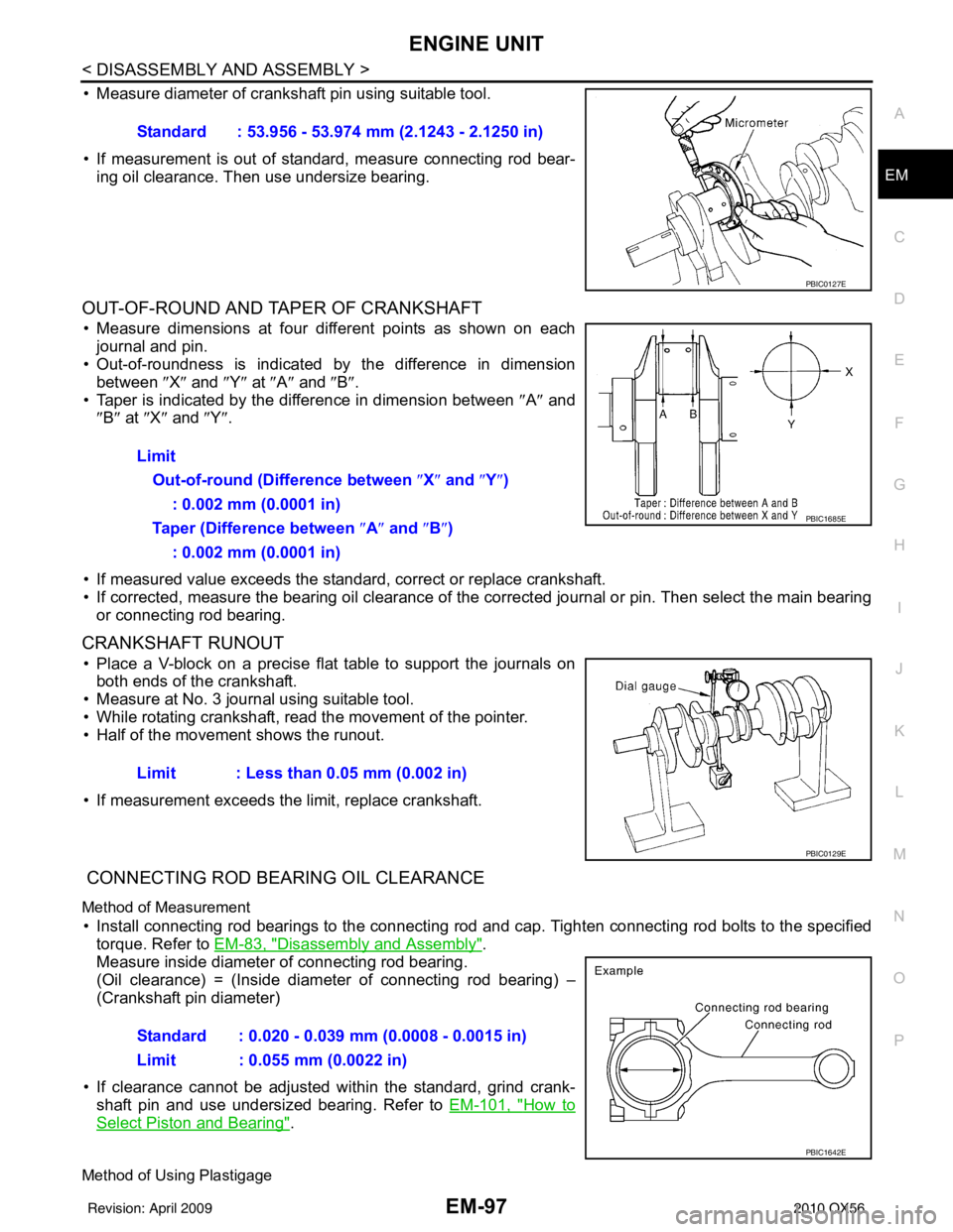
• Measure diameter of crankshaft pin using suitable tool.
• If measurement is out of standard, measure connecting rod bear-
ing oil clearance. Then use undersize bearing.
OUT-OF-ROUND AND TAPER OF CRANKSHAFT
• Measure dimensions at four di fferent points as shown on each
journal and pin.
• Out-of-roundness is indicated by the difference in dimension
between ″X″ and ″Y″ at ″A″ and ″B″ .
• Taper is indicated by the difference in dimension between ″A ″ and
″ B″ at ″X ″ and ″Y″ .
• If measured value exceeds the standard, correct or replace crankshaft.
• If corrected, measure the bearing oil clearance of the corrected journal or pin. Then select the main bearing or connecting rod bearing.
CRANKSHAFT RUNOUT
• Place a V-block on a precise flat table to support the journals onboth ends of the crankshaft.
• Measure at No. 3 journal using suitable tool.
• While rotating crankshaft, read the movement of the pointer.
• Half of the movement shows the runout.
• If measurement exceeds the limit, replace crankshaft.
CONNECTING ROD BEARING OIL CLEARANCE
Method of Measurement
• Install connecting rod bearings to the connecting rod and cap. Tighten connecting rod bolts to the specified
torque. Refer to EM-83, "
Disassembly and Assembly".
Measure inside diameter of connecting rod bearing.
(Oil clearance) = (Inside diameter of connecting rod bearing) –
(Crankshaft pin diameter)
• If clearance cannot be adjusted wit hin the standard, grind crank-
shaft pin and use undersized bearing. Refer to EM-101, "
How to
Select Piston and Bearing".
Method of Using Plastigage
Standard : 53.956 - 53.974 mm (2.1243 - 2.1250 in)
PBIC0127E
Limit
Out-of-round (Difference between ″X ″ and ″ Y″)
: 0.002 mm (0.0001 in)
Taper (Difference between ″ A″ and ″B ″)
: 0.002 mm (0.0001 in)
PBIC1685E
Limit : Less than 0.05 mm (0.002 in)
PBIC0129E
Standard : 0.020 - 0.039 mm (0.0008 - 0.0015 in)
Limit : 0.055 mm (0.0022 in)
PBIC1642E
Revision: April 20092010 QX56
Page 1949 of 4210
EM-98
< DISASSEMBLY AND ASSEMBLY >
ENGINE UNIT
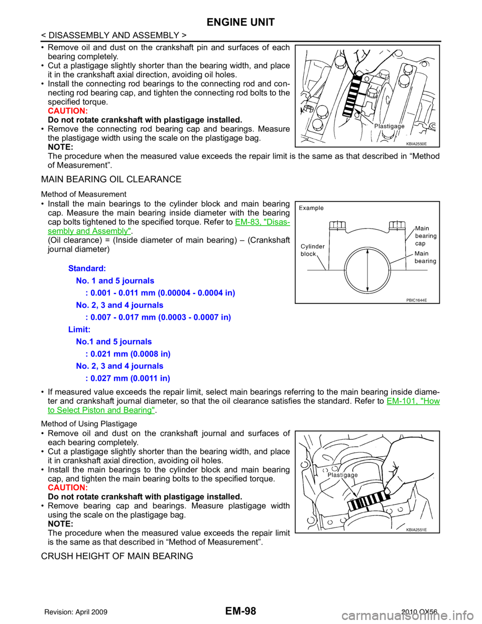
• Remove oil and dust on the crankshaft pin and surfaces of eachbearing completely.
• Cut a plastigage slightly shorter than the bearing width, and place
it in the crankshaft axial direction, avoiding oil holes.
• Install the connecting rod beari ngs to the connecting rod and con-
necting rod bearing cap, and tighten the connecting rod bolts to the
specified torque.
CAUTION:
Do not rotate crankshaft with plastigage installed.
• Remove the connecting rod bear ing cap and bearings. Measure
the plastigage width using the scale on the plastigage bag.
NOTE:
The procedure when the measured value exceeds the repair limit is the same as that described in “Method
of Measurement”.
MAIN BEARING OIL CLEARANCE
Method of Measurement
• Install the main bearings to the cylinder block and main bearing cap. Measure the main bearing inside diameter with the bearing
cap bolts tightened to the specified torque. Refer to EM-83, "
Disas-
sembly and Assembly".
(Oil clearance) = (Inside diameter of main bearing) – (Crankshaft
journal diameter)
• If measured value exceeds the repair limit, select main bearings referring to the main bearing inside diame-
ter and crankshaft journal diameter, so that the oil clearance satisfies the standard. Refer to EM-101, "
How
to Select Piston and Bearing".
Method of Using Plastigage
• Remove oil and dust on the crankshaft journal and surfaces of
each bearing completely.
• Cut a plastigage slightly shorter than the bearing width, and place it in crankshaft axial direction, avoiding oil holes.
• Install the main bearings to the cylinder block and main bearing cap, and tighten the main bearing bolts to the specified torque.
CAUTION:
Do not rotate crankshaft with plastigage installed.
• Remove bearing cap and bearings. Measure plastigage width using the scale on the plastigage bag.
NOTE:
The procedure when the measured value exceeds the repair limit
is the same as that descri bed in “Method of Measurement”.
CRUSH HEIGHT OF MAIN BEARING
KBIA2550E
Standard:
No. 1 and 5 journals : 0.001 - 0.011 mm (0.00004 - 0.0004 in)
No. 2, 3 and 4 journals : 0.007 - 0.017 mm (0.0003 - 0.0007 in)
Limit: No.1 and 5 journals : 0.021 mm (0.0008 in)
No. 2, 3 and 4 journals : 0.027 mm (0.0011 in)
PBIC1644E
KBIA2551E
Revision: April 20092010 QX56
Page 1983 of 4210
HEADLAMPEXL-7
< FUNCTION DIAGNOSIS >
C
DE
F
G H
I
J
K
M A
B
EXL
N
O P
FUNCTION DIAGNOSIS
HEADLAMP
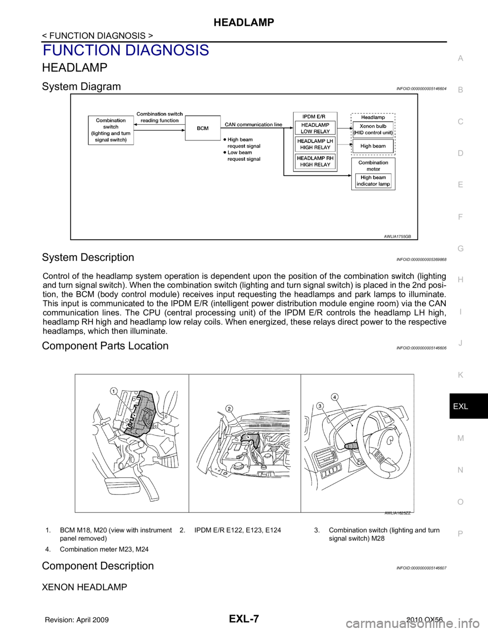
System DiagramINFOID:0000000005146604
System DescriptionINFOID:0000000005369868
Control of the headlamp system operation is dependent upon t he position of the combination switch (lighting
and turn signal switch). When the combination switch (lighting and turn signal switch) is placed in the 2nd posi-
tion, the BCM (body control module) receives input requesting the headlamps and park lamps to illuminate.
This input is communicated to the IPDM E/R (intelligent power distribution module engine room) via the CAN
communication lines. The CPU (central processing unit) of the IPDM E/R controls the headlamp LH high,
headlamp RH high and headlamp low relay coils. When energiz ed, these relays direct power to the respective
headlamps, which then illuminate.
Component Parts LocationINFOID:0000000005146606
Component DescriptionINFOID:0000000005146607
XENON HEADLAMP
AWLIA1755GB
1. BCM M18, M20 (view with instrument
panel removed) 2. IPDM E/R E122, E123, E124 3. Combination switch (lighting and turn
signal switch) M28
4. Combination meter M23, M24
AWLIA1625ZZ
Revision: April 20092010 QX56
Page 1998 of 4210

EXL-22
< FUNCTION DIAGNOSIS >
DIAGNOSIS SYSTEM (IPDM E/R)
DIAGNOSIS SYSTEM (IPDM E/R)
Diagnosis DescriptionINFOID:0000000005369886
AUTO ACTIVE TEST
Description
In auto active test mode, the IPDM E/R sends a drive signal to the follo wing systems to check their operation.
• Oil pressure low/coolant pressure high warning indicator
• Oil pressure gauge
• Rear window defogger
• Front wipers
• Tail, license and parking lamps
• Front fog lamps
• Headlamps (Hi, Lo)
• A/C compressor (magnetic clutch)
• Cooling fan
Operation Procedure
1. Close the hood and front door RH, and lift the wiper a rms from the windshield (to prevent windshield dam-
age due to wiper operation).
NOTE:
When auto active test is performed with hood opened, sprinkle water on windshield before hand.
2. Turn ignition switch OFF.
3. Turn the ignition switch ON and, within 20 seconds, press the front door switch LH 10 times. Then turn the ignition switch OFF.
4. Turn the ignition switch ON within 10 seconds. Af ter that the horn sounds once and the auto active test
starts.
5. After a series of the following operations is repeated 3 times, auto active test is completed.
NOTE:
When auto active test mode has to be cancelled halfway through test, turn ignition switch OFF.
CAUTION:
• If auto active test mode cannot be actuated, check door switch system. Refer to DLK-71, "
Descrip-
tion".
• Do not start the engine.
Inspection in Auto Active Test Mode
When auto active test mode is actuated, the following 7 steps are repeated 3 times.
Operation
sequence Inspection Location
Operation
1 Rear window defogger 10 seconds
2 Front wipers LO for 5 seconds → HI for 5 seconds
WKIA4655E
Revision: April 20092010 QX56
Page 2083 of 4210
BCM (BODY CONTROL MODULE)EXL-107
< ECU DIAGNOSIS >
C
DE
F
G H
I
J
K
M A
B
EXL
N
O P
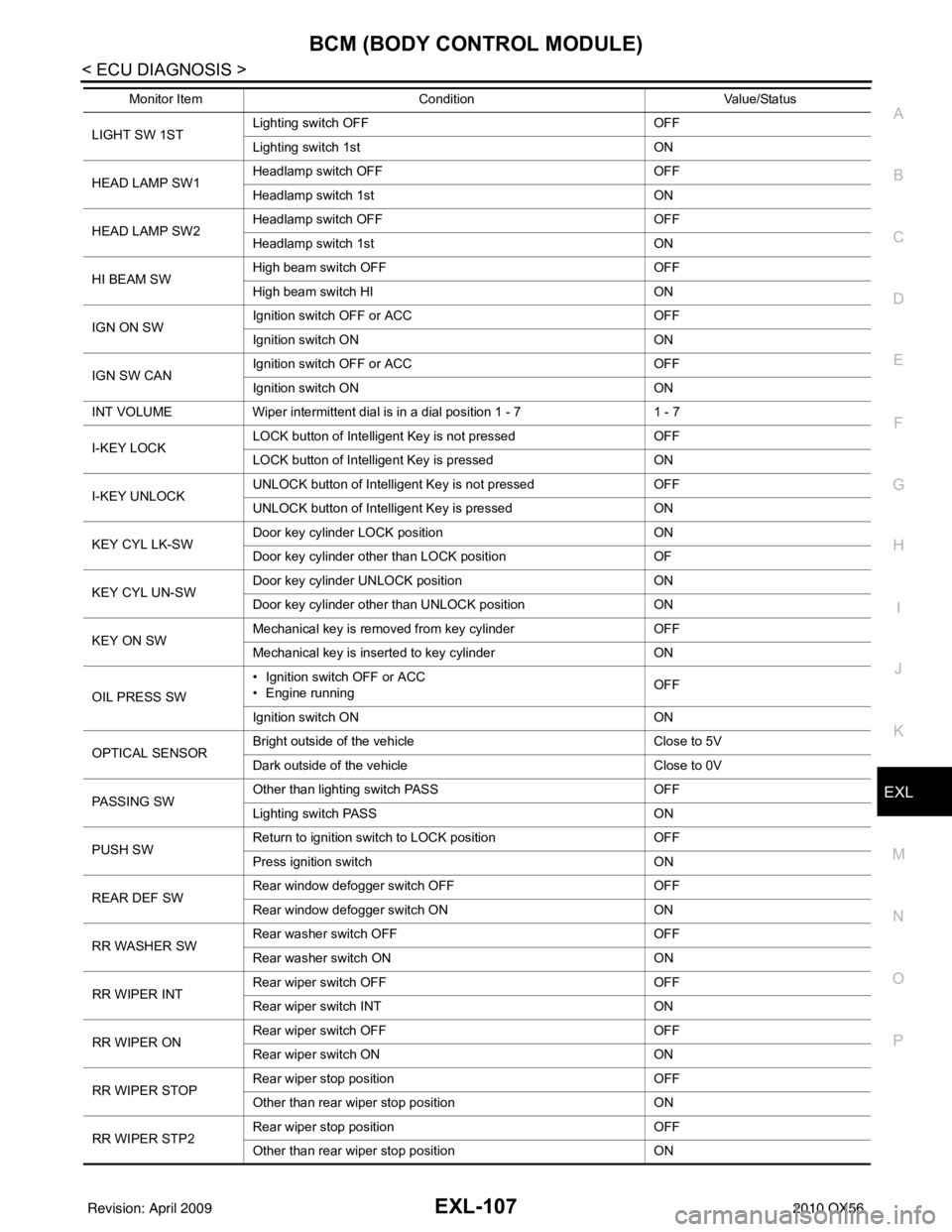
LIGHT SW 1ST Lighting switch OFF OFF
Lighting switch 1st
ON
HEAD LAMP SW1 Headlamp switch OFF
OFF
Headlamp switch 1st ON
HEAD LAMP SW2 Headlamp switch OFF
OFF
Headlamp switch 1st ON
HI BEAM SW High beam switch OFF
OFF
High beam switch HI ON
IGN ON SW Ignition switch OFF or ACC
OFF
Ignition switch ON ON
IGN SW CAN Ignition switch OFF or ACC
OFF
Ignition switch ON ON
INT VOLUME Wiper intermittent dial is in a dial position 1 - 7 1 - 7
I-KEY LOCK LOCK button of Intelligent Key is not pressed
OFF
LOCK button of Intelligent Key is pressed ON
I-KEY UNLOCK UNLOCK button of Intelligent Key is not pressed
OFF
UNLOCK button of Intelligent Key is pressed ON
KEY CYL LK-SW Door key cylinder LOCK position
ON
Door key cylinder other than LOCK position OF
KEY CYL UN-SW Door key cylinder UNLOCK position
ON
Door key cylinder other than UNLOCK position ON
KEY ON SW Mechanical key is removed from key cylinder
OFF
Mechanical key is inserted to key cylinder ON
OIL PRESS SW • Ignition switch OFF or ACC
• Engine running
OFF
Ignition switch ON ON
OPTICAL SENSOR Bright outside of the vehicle
Close to 5V
Dark outside of the vehicle Close to 0V
PASSING SW Other than lighting switch PASS
OFF
Lighting switch PASS ON
PUSH SW Return to ignition switch to LOCK position
OFF
Press ignition switch ON
REAR DEF SW Rear window defogger switch OFF
OFF
Rear window defogger switch ON ON
RR WASHER SW Rear washer switch OFF
OFF
Rear washer switch ON ON
RR WIPER INT Rear wiper switch OFF
OFF
Rear wiper switch INT ON
RR WIPER ON Rear wiper switch OFF
OFF
Rear wiper switch ON ON
RR WIPER STOP Rear wiper stop position
OFF
Other than rear wiper stop position ON
RR WIPER STP2 Rear wiper stop position
OFF
Other than rear wiper stop position ON
Monitor Item
Condition Value/Status
Revision: April 20092010 QX56
Page 2098 of 4210

EXL-122
< ECU DIAGNOSIS >
IPDM E/R (INTELLIGENT POWER DISTRIBUTION MODULE ENGINE ROOM)
IPDM E/R (INTELLIGENT POWER DISTRIBUTION MODULE ENGINE
ROOM)
Reference ValueINFOID:0000000005369897
VALUES ON THE DIAGNOSIS TOOL
Monitor Item ConditionValue/Status
MOTOR FAN REQ Engine idle speed Changes depending on engine
coolant temperature, air conditioner
operation status, vehicle speed,
etc.0 - 100 %
A/C COMP REQ A/C switch OFF
OFF
A/C switch ON ON
TAIL&CLR REQ Lighting switch OFF
OFF
Lighting switch 1ST, 2ND, HI or AUTO (Light is illuminated) ON
HL LO REQ Lighting switch OFF
OFF
Lighting switch 2ND HI or AUTO (Light is illuminated) ON
HL HI REQ Lighting switch OFF
OFF
Lighting switch HI ON
FR FOG REQ Lighting switch 2ND or AUTO (Light
is illuminated) Front fog lamp switch OFF OFF
• Front fog lamp switch ON
• Daytime light activated (Canada
only) ON
FR WIP REQ Ignition switch ON Front wiper switch OFF
STOP
Front wiper switch INT 1LOW
Front wiper switch LO LOW
Front wiper switch HI HI
WIP AUTO STOP Ignition switch ON Front wiper stop position
STOP P
Any position other than front wiper
stop position ACT P
WIP PROT Ignition switch ON Front wiper operates normally OFF
Front wiper stops at fail-safe opera-
tion
BLOCK
ST RLY REQ Ignition switch OFF or ACC
OFF
Ignition switch START ON
IGN RLY Ignition switch OFF or ACC
OFF
Ignition switch ON ON
RR DEF REQ Rear defogger switch OFF
OFF
Rear defogger switch ON ON
OIL P SW Ignition switch OFF, ACC or engine running
OPEN
Ignition switch ON CLOSE
DTRL REQ Daytime light system requested OFF with CONSULT-III.
OFF
Daytime light system requested ON with CONSULT-III. ON
HOOD SW Hood closed.
OFF
Hood open. ON
Revision: April 20092010 QX56