Page 3882 of 4210
TRANSMISSION ASSEMBLYTM-187
< REMOVAL AND INSTALLATION >
CEF
G H
I
J
K L
M A
B
TM
N
O P
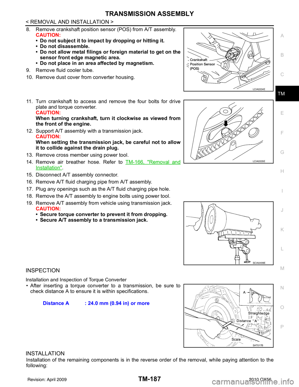
8. Remove crankshaft position sens or (POS) from A/T assembly.
CAUTION:
• Do not subject it to impact by dropping or hitting it.
• Do not disassemble.
• Do not allow metal filings or foreign material to get on the
sensor front edge magnetic area.
• Do not place in an area affected by magnetism.
9. Remove fluid cooler tube.
10. Remove dust cover from converter housing.
11. Turn crankshaft to access and remove the four bolts for drive plate and torque converter.
CAUTION:
When turning crankshaft, turn it clockwise as viewed from
the front of the engine.
12. Support A/T assembly with a transmission jack. CAUTION:
When setting the transmission jack, be careful not to allow
it to collide agai nst the drain plug.
13. Remove cross member using power tool.
14. Remove air breather hose. Refer to TM-166, "
Removal and
Installation".
15. Disconnect A/T assembly connector.
16. Remove A/T fluid charging pipe from A/T assembly.
17. Plug any openings such as the A/T fluid charging pipe hole.
18. Remove the A/T assembly to engine bolts using power tool.
19. Remove A/T assembly from vehicle using transmission jack. CAUTION:
• Secure torque converter to prevent it from dropping.
• Secure A/T assembly to a transmission jack.
INSPECTION
Installation and Inspection of Torque Converter
• After inserting a torque converter to a transmission, be sure to check distance A to ensure it is within specifications.
INSTALLATION
Installation of the remaining components is in the revers e order of the removal, while paying attention to the
following:
LCIA0334E
LCIA0335E
SCIA0499E
Distance A : 24.0 mm (0.94 in) or more
SAT017B
Revision: April 20092010 QX56
Page 3883 of 4210
TM-188
< REMOVAL AND INSTALLATION >
TRANSMISSION ASSEMBLY
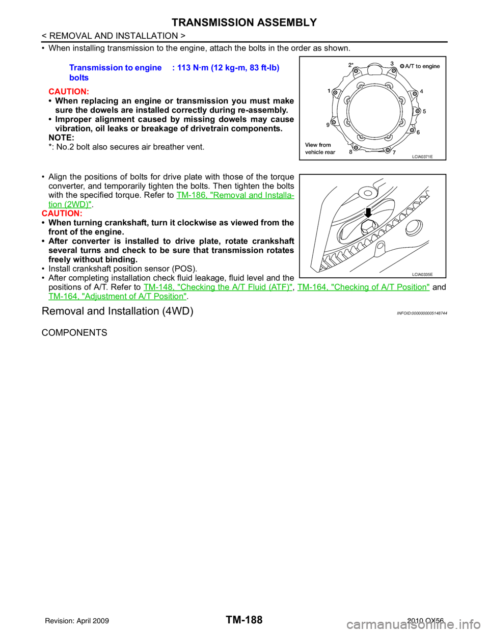
• When installing transmission to the engine, attach the bolts in the order as shown.CAUTION:
• When replacing an engine or transmission you must make
sure the dowels are installe d correctly during re-assembly.
• Improper alignment caused by missing dowels may cause
vibration, oil leaks or breakage of drivetrain components.
NOTE:
*: No.2 bolt also secures air breather vent.
• Align the positions of bolts for drive plate with those of the torque converter, and temporarily tighten the bolts. Then tighten the bolts
with the specified torque. Refer to TM-186, "
Removal and Installa-
tion (2WD)".
CAUTION:
• When turning crankshaft, turn it clockwise as viewed from the front of the engine.
• After converter is installed to drive plate, rotate crankshaft
several turns and check to be sure that transmission rotates
freely without binding.
• Install crankshaft pos ition sensor (POS).
• After completing installation check fluid leakage, fluid level and the
positions of A/T. Refer to TM-148, "
Checking the A/T Fluid (ATF)", TM-164, "Checking of A/T Position" and
TM-164, "
Adjustment of A/T Position".
Removal and Installation (4WD)INFOID:0000000005148744
COMPONENTS
Transmission to engine
bolts : 113 N·m (12 kg-m, 83 ft-lb)
LCIA0371E
LCIA0335E
Revision: April 20092010 QX56
Page 3885 of 4210
TM-190
< REMOVAL AND INSTALLATION >
TRANSMISSION ASSEMBLY
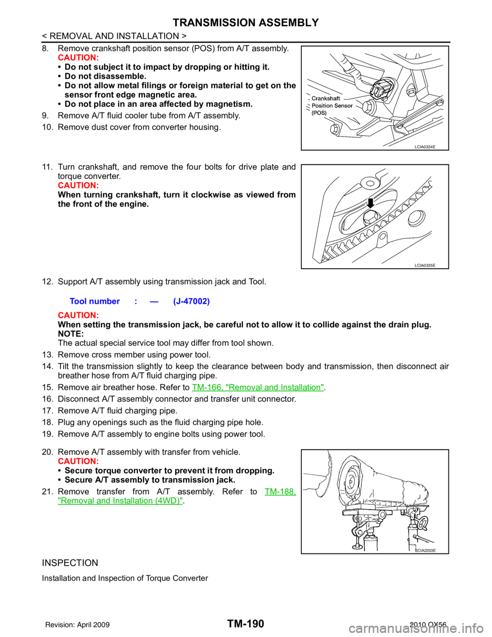
8. Remove crankshaft position sensor (POS) from A/T assembly.CAUTION:
• Do not subject it to impact by dropping or hitting it.
• Do not disassemble.
• Do not allow metal filings or fo reign material to get on the
sensor front edge magnetic area.
• Do not place in an area affected by magnetism.
9. Remove A/T fluid cooler tube from A/T assembly.
10. Remove dust cover from converter housing.
11. Turn crankshaft, and remove the four bolts for drive plate and torque converter.
CAUTION:
When turning crankshaft, turn it clockwise as viewed from
the front of the engine.
12. Support A/T assembly using transmission jack and Tool. CAUTION:
When setting the transmission jack, be careful not to allow it to collide against the drain plug.
NOTE:
The actual special service tool may differ from tool shown.
13. Remove cross member using power tool.
14. Tilt the transmission slightly to keep the cl earance between body and transmission, then disconnect air
breather hose from A/T fluid charging pipe.
15. Remove air breather hose. Refer to TM-166, "
Removal and Installation".
16. Disconnect A/T assembly connector and transfer unit connector.
17. Remove A/T fluid charging pipe.
18. Plug any openings such as the fluid charging pipe hole.
19. Remove A/T assembly to engine bolts using power tool.
20. Remove A/T assembly with transfer from vehicle. CAUTION:
• Secure torque converter to prevent it from dropping.
• Secure A/T assembly to transmission jack.
21. Remove transfer from A/T assembly. Refer to TM-188,
"Removal and Installation (4WD)".
INSPECTION
Installation and Inspection of Torque Converter
LCIA0334E
LCIA0335E
Tool number : — (J-47002)
SCIA2203E
Revision: April 20092010 QX56
Page 3886 of 4210
TRANSMISSION ASSEMBLYTM-191
< REMOVAL AND INSTALLATION >
CEF
G H
I
J
K L
M A
B
TM
N
O P
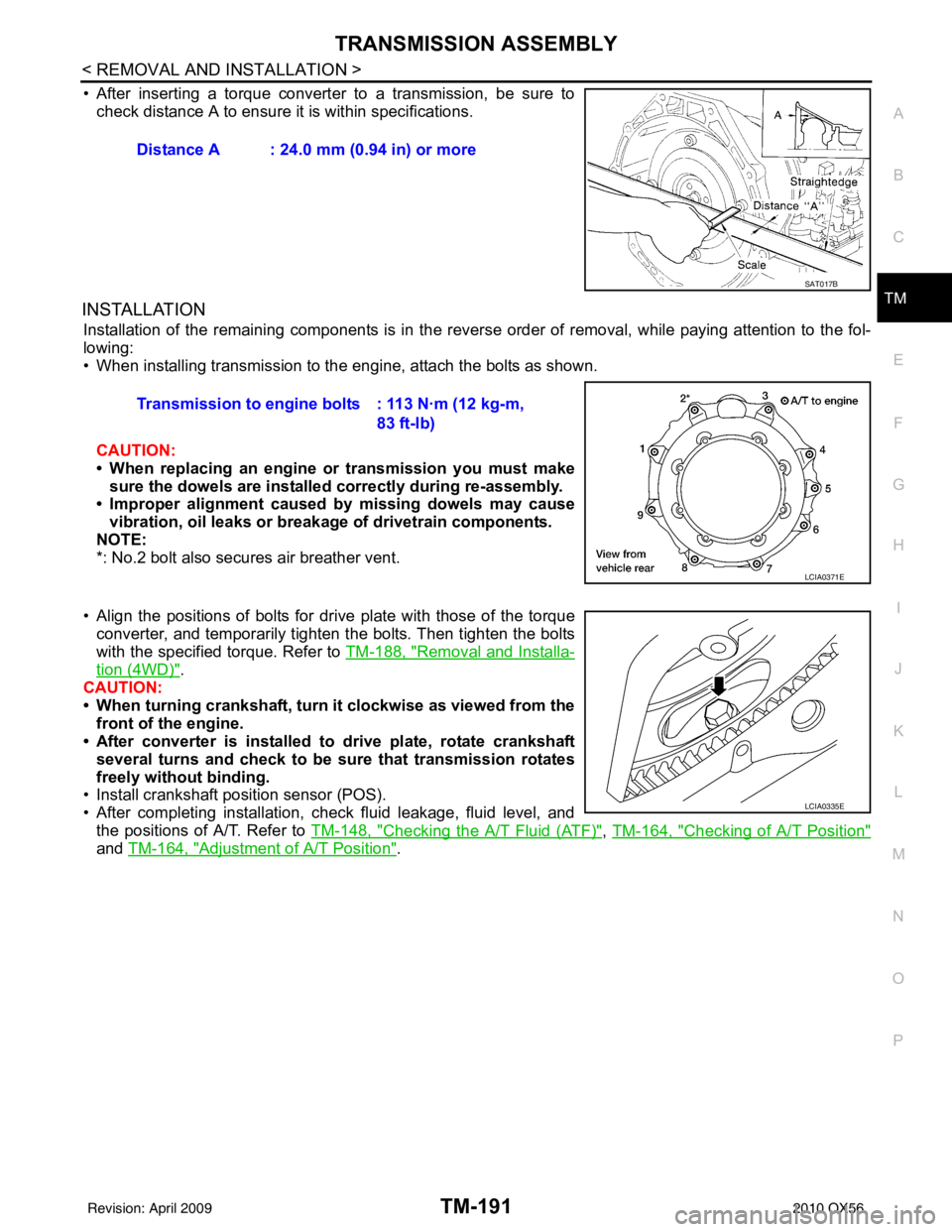
• After inserting a torque converter to a transmission, be sure to check distance A to ensure it is within specifications.
INSTALLATION
Installation of the remaining components is in the revers e order of removal, while paying attention to the fol-
lowing:
• When installing transmission to the engine, attach the bolts as shown.
CAUTION:
• When replacing an engine or transmission you must make sure the dowels are installed correctly during re-assembly.
• Improper alignment caused by missing dowels may cause
vibration, oil leaks or breakage of drivetrain components.
NOTE:
*: No.2 bolt also secures air breather vent.
• Align the positions of bolts for dr ive plate with those of the torque
converter, and temporarily tighten the bolts. Then tighten the bolts
with the specified torque. Refer to TM-188, "
Removal and Installa-
tion (4WD)".
CAUTION:
• When turning crankshaft, turn it clockwise as viewed from the
front of the engine.
• After converter is installed to drive plate, rotate crankshaft
several turns and check to be sure that transmission rotates
freely without binding.
• Install crankshaft position sensor (POS).
• After completing installation, check fluid leakage, fluid level, and
the positions of A/T. Refer to TM-148, "
Checking the A/T Fluid (ATF)", TM-164, "Checking of A/T Position"
and TM-164, "Adjustment of A/T Position".
Distance A : 24.0 mm (0.94 in) or more
SAT017B
Transmission to engine bolts : 113 N·m (12 kg-m,
83 ft-lb)
LCIA0371E
LCIA0335E
Revision: April 20092010 QX56
Page 3899 of 4210
TM-204
< DISASSEMBLY AND ASSEMBLY >
DISASSEMBLY
DISASSEMBLY
DisassemblyINFOID:0000000005148748
CAUTION:
Do not disassemble parts behind Drum Support. Refer to TM-8, "
Cross-Sectional View (2WD models)".
1. Drain A/T fluid through drain plug.
2. Remove torque converter by holding it firmly and turing while pulling straight out.
3. Check torque converter one-way clutch using a check tool as shown.
a. Insert a check tool into the groove of bearing support built into one-way clutch outer race.
b. While holding bearing support with a check tool, rotate one-way clutch spline using suitable tool.
c. Make sure that inner race rotates clockwise only. If not, replace torque converter assembly.
4. Remove bolts and converter housing from transmission case. CAUTION:
Do not scratch converter housing.
• Self-sealing bolt (A)
SCIA5010E
SCIA3171E
WCIA0662E
Revision: April 20092010 QX56
Page 3972 of 4210
VTL-10
< ON-VEHICLE REPAIR >
OPTICAL SENSOR
OPTICAL SENSOR
Removal and InstallationINFOID:0000000005147607
REMOVAL
1. Remove the defroster grille from the instrument panel. Refer to VTL-36, "Removal and Installation".
2. Disconnect the optical sensor connector (2).
3. Twist the optical sensor (1) counter clockwise to remove it from the defroster grille.
INSTALLATION
Installation is in the reverse order of removal.
ALIIA0061ZZ
Revision: April 20092010 QX56
Page 3999 of 4210
DUCTS AND GRILLESVTL-37
< ON-VEHICLE REPAIR >
C
DE
F
G H
J
K L
M A
B
VTL
N
O P
REAR OVERHEAD DUCTS
Removal
1. Remove the luggage side finisher lower RH. Refer to INT-19, "Removal and Installation".
2. Remove the headliner. Refer to INT-17, "
Removal and Installation".
NOTE:
The rear headliner duct connected to the rear over head duct is part of the headlining trim panel and is
replaced as an assembly.
3. Remove the two bolts and remove the rear upper and lower overhead ducts.
Installation
Installation is in the reverse order of removal.
REAR FLOOR DUCT
Removal
1. Remove the luggage side finisher lower RH. Refer to INT-19, "Removal and Installation".
2. Reposition the floor carpet out of the way.
3. Remove the two bolts and remove the rear floor duct.
Installation
Installation is in the reverse order of removal.
GRILLES
Removal
1. Remove the interior trim panels as necessary. Refer to IP-12, "Removal and Installation" or INT-14,
"Removal and Installation".
2. Remove the grille from the interior trim panel. NOTE:
To remove the rear roof console grilles, turn the grille counter-clockwise to release the grille from the rear
roof console.
Installation
Installation is in the reverse order of removal.
Revision: April 20092010 QX56
Page 4054 of 4210
WCS
BCM (BODY CONTROL MODULE)WCS-55
< ECU DIAGNOSIS >
C
DE
F
G H
I
J
K L
M B A
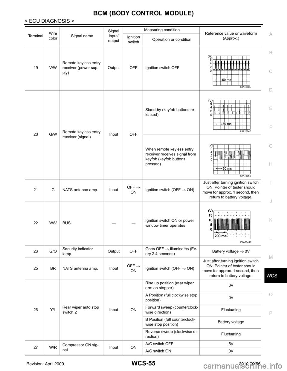
O P19 V/W Remote keyless entry
receiver (power sup-
ply) Output OFF Ignition switch OFF
20 G/W Remote keyless entry
receiver (signal) Input OFFStand-by (keyfob buttons re-
leased)
When remote keyless entry
receiver receives signal from
keyfob (keyfob buttons
pressed)
21 G NATS antenna amp. Input OFF
→
ON Ignition switch (OFF → ON) Just after turning ignition switch
ON: Pointer of tester should
move for approx. 1 second, then return to battery voltage.
22 W/V BUS — —Ignition switch ON or power
window timer operates
23 G/O Security indicator
lamp Output OFF
Goes OFF
→ illuminates (Ev-
ery 2.4 seconds) Battery voltage
→ 0V
25 BR NATS antenna amp. Input OFF
→
ON Ignition switch (OFF → ON) Just after turning ignition switch
ON: Pointer of tester should
move for approx. 1 second, then return to battery voltage.
26 Y/L Rear wiper auto stop
switch 2 Input ONRise up position (rear wiper
arm on stopper)
0V
A Position (full clockwise stop
position) 0V
Forward sweep (counterclock-
wise direction) Fluctuating
B Position (full counterclock-
wise stop position) Battery voltage
Reverse sweep (clockwise di-
rection) Fluctuating
27 W/R Compressor ON sig-
nal Input ONA/C switch OFF
5V
A/C switch ON 0V
Te r m i n a l
Wire
color Signal name Signal
input/
output Measuring condition
Reference value or waveform
(Approx.)
Ignition
switch Operation or condition
LIIA1893E
LIIA1894E
LIIA1895E
PIIA2344E
Revision: April 20092010 QX56