2010 INFINITI QX56 clock
[x] Cancel search: clockPage 2551 of 4210
INL-82
< ON-VEHICLE REPAIR >
ILLUMINATION
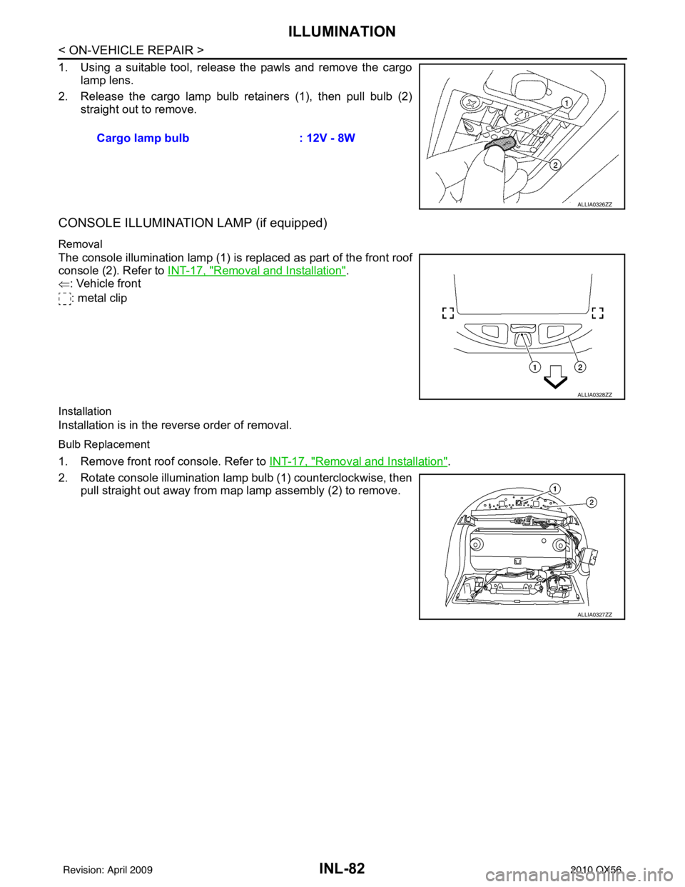
1. Using a suitable tool, release the pawls and remove the cargolamp lens.
2. Release the cargo lamp bulb retainers (1), then pull bulb (2) straight out to remove.
CONSOLE ILLUMINATION LAMP (if equipped)
Removal
The console illumination lamp (1) is replaced as part of the front roof
console (2). Refer to INT-17, "
Removal and Installation".
⇐ : Vehicle front
: metal clip
Installation
Installation is in the reverse order of removal.
Bulb Replacement
1. Remove front roof console. Refer to INT-17, "Removal and Installation".
2. Rotate console illumination lamp bulb (1) counterclockwise, then pull straight out away from map lamp assembly (2) to remove.Cargo lamp bulb
: 12V - 8W
ALLIA0326ZZ
ALLIA0328ZZ
ALLIA0327ZZ
Revision: April 20092010 QX56
Page 2554 of 4210
INT-2
< SYMPTOM DIAGNOSIS >
SQUEAK AND RATTLE TROUBLE DIAGNOSES
SYMPTOM DIAGNOSIS
SQUEAK AND RATTLE TROUBLE DIAGNOSES
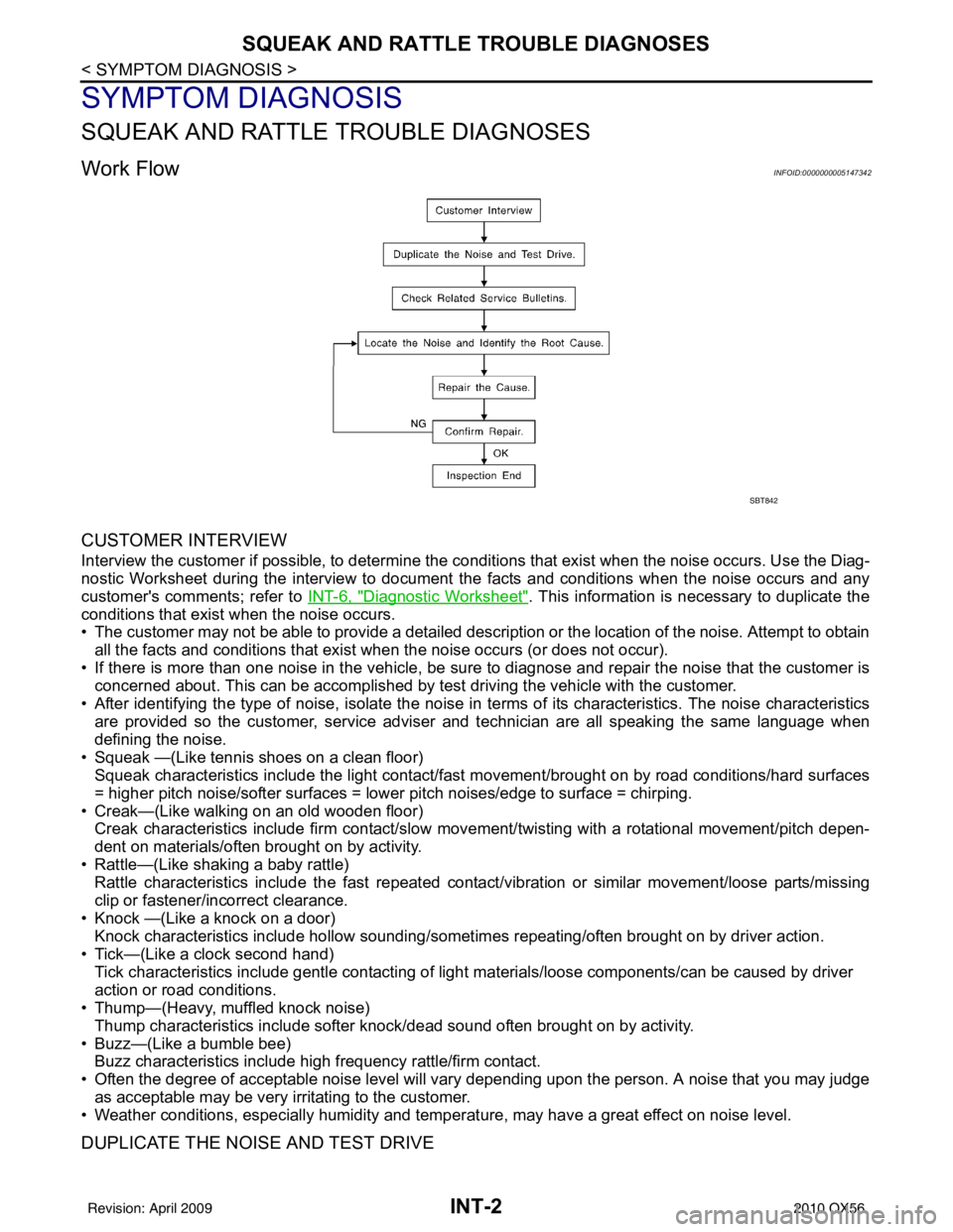
Work FlowINFOID:0000000005147342
CUSTOMER INTERVIEW
Interview the customer if possible, to determine the conditions that exist when the noise occurs. Use the Diag-
nostic Worksheet during the interview to document the facts and conditions when the noise occurs and any
customer's comments; refer to INT-6, "
Diagnostic Worksheet". This information is necessary to duplicate the
conditions that exist when the noise occurs.
• The customer may not be able to provide a detailed description or the location of the noise. Attempt to obtain
all the facts and conditions that exist w hen the noise occurs (or does not occur).
• If there is more than one noise in the vehicle, be sure to diagnose and repair the noise that the customer is
concerned about. This can be accomplished by test driving the vehicle with the customer.
• After identifying the type of noise, isolate the noise in terms of its characteristics. The noise characteristics
are provided so the customer, service adviser and technician are all speaking the same language when
defining the noise.
• Squeak —(Like tennis shoes on a clean floor) Squeak characteristics include the light contact/fast movement/brought on by road conditions/hard surfaces
= higher pitch noise/softer surfaces = lower pitch noises/edge to surface = chirping.
• Creak—(Like walking on an old wooden floor) Creak characteristics include firm contact/slow mo vement/twisting with a rotational movement/pitch depen-
dent on materials/often brought on by activity.
• Rattle—(Like shaking a baby rattle) Rattle characteristics include the fast repeated contac t/vibration or similar movement/loose parts/missing
clip or fastener/incorrect clearance.
• Knock —(Like a knock on a door) Knock characteristics include hollow sounding/someti mes repeating/often brought on by driver action.
• Tick—(Like a clock second hand) Tick characteristics include gentle contacting of light materials/loose components/can be caused by driver
action or road conditions.
• Thump—(Heavy, muffled knock noise)
Thump characteristics include softer k nock/dead sound often brought on by activity.
• Buzz—(Like a bumble bee) Buzz characteristics include hi gh frequency rattle/firm contact.
• Often the degree of acceptable noise level will vary depending upon the person. A noise that you may judge as acceptable may be very irritating to the customer.
• Weather conditions, especially humidity and temperat ure, may have a great effect on noise level.
DUPLICATE THE NOISE AND TEST DRIVE
SBT842
Revision: April 20092010 QX56
Page 2578 of 4210
SQUEAK AND RATTLE TROUBLE DIAGNOSESIP-5
< SYMPTOM DIAGNOSIS >
C
DE
F
G H
I
K L
M A
B
IP
N
O P
SYMPTOM DIAGNOSIS
SQUEAK AND RATTLE TROUBLE DIAGNOSES
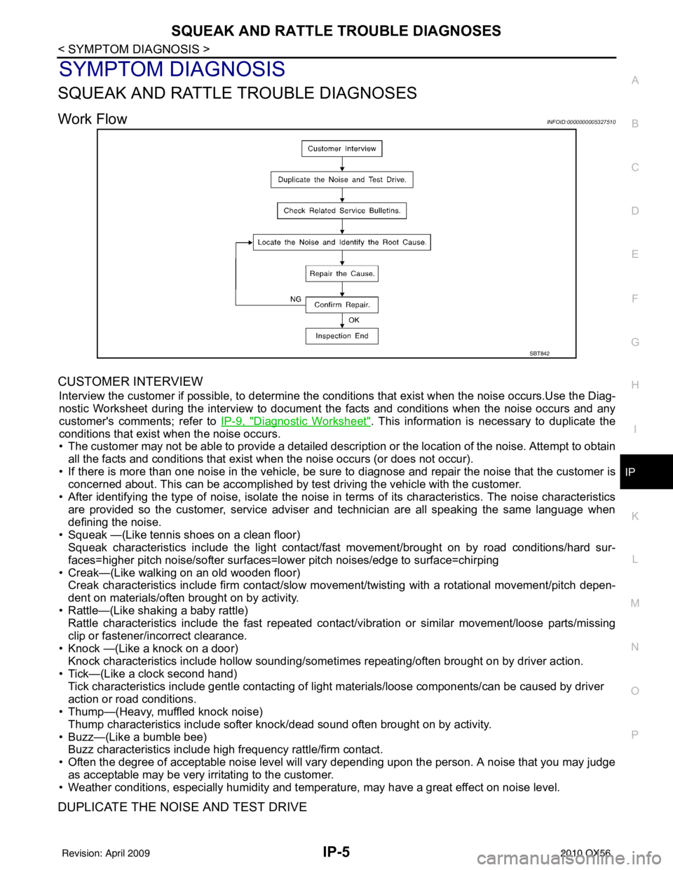
Work FlowINFOID:0000000005327510
CUSTOMER INTERVIEW
Interview the customer if possible, to determine the conditions that exist when the noise occurs.Use the Diag-
nostic Worksheet during the interv iew to document the facts and conditions when the noise occurs and any
customer's comments; refer to IP-9, "
Diagnostic Worksheet". This information is necessary to duplicate the
conditions that exist when the noise occurs.
• The customer may not be able to provide a detailed descr iption or the location of the noise. Attempt to obtain
all the facts and conditions that exist when the noise occurs (or does not occur).
• If there is more than one noise in the vehicle, be sure to diagnose and repair the noise that the customer is
concerned about. This can be accomplished by test driving the vehicle with the customer.
• After identifying the type of noise, isolate the noise in terms of its characteristics. The noise characteristics are provided so the customer, service adviser and technician are all speaking the same language when
defining the noise.
• Squeak —(Like tennis shoes on a clean floor) Squeak characteristics include the light contact/fast movement/brought on by road conditions/hard sur-
faces=higher pitch noise/softer surfaces=lower pitch noises/edge to surface=chirping
• Creak—(Like walking on an old wooden floor) Creak characteristics include firm contact/slow mo vement/twisting with a rotational movement/pitch depen-
dent on materials/often brought on by activity.
• Rattle—(Like shaking a baby rattle) Rattle characteristics include the fast repeated contac t/vibration or similar movement/loose parts/missing
clip or fastener/incorrect clearance.
• Knock —(Like a knock on a door) Knock characteristics include hollow sounding/someti mes repeating/often brought on by driver action.
• Tick—(Like a clock second hand) Tick characteristics include gentle contacting of li ght materials/loose components/can be caused by driver
action or road conditions.
• Thump—(Heavy, muffled knock noise)
Thump characteristics include softer k nock/dead sound often brought on by activity.
• Buzz—(Like a bumble bee) Buzz characteristics include high frequency rattle/firm contact.
• Often the degree of acceptable noise level will vary depending upon the person. A noise that you may judge as acceptable may be very irritating to the customer.
• Weather conditions, especially humidity and temperature, may have a great effect on noise level.
DUPLICATE THE NOISE AND TEST DRIVE
SBT842
Revision: April 20092010 QX56
Page 2588 of 4210
CLUSTER LID CIP-15
< ON-VEHICLE REPAIR >
C
DE
F
G H
I
K L
M A
B
IP
N
O P
CLUSTER LID C
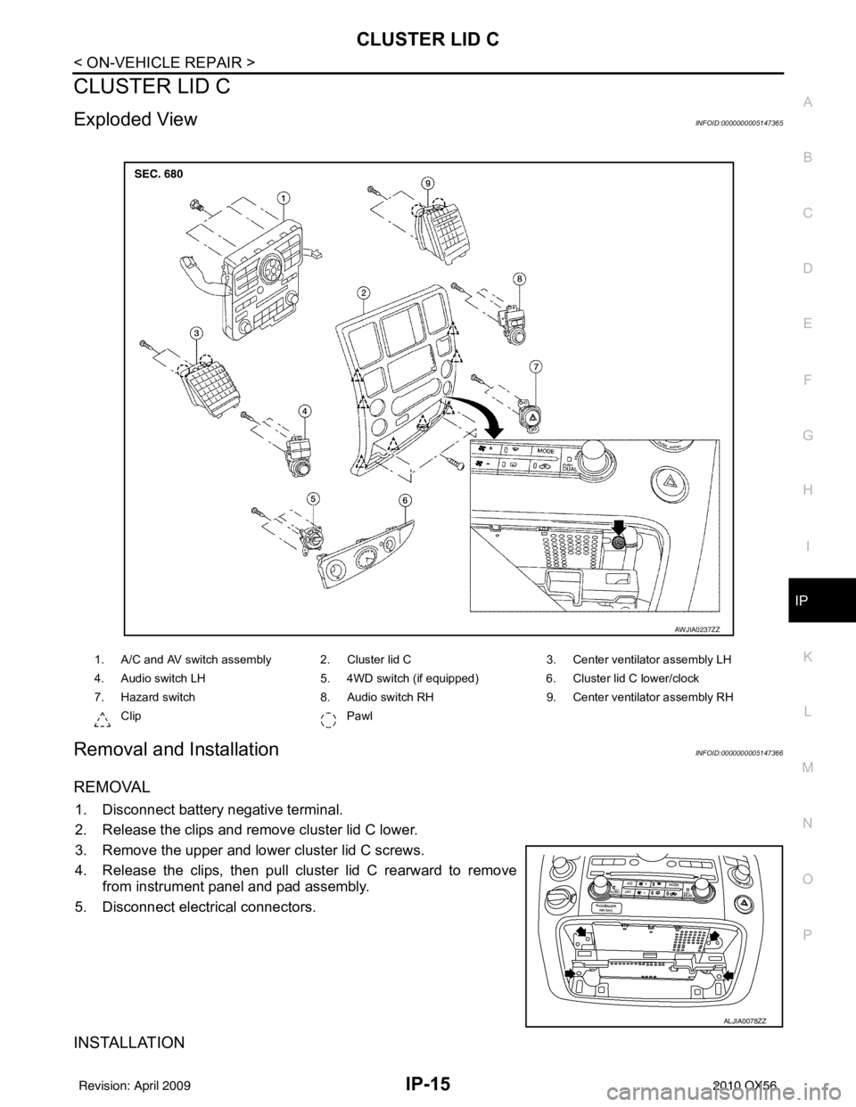
Exploded ViewINFOID:0000000005147365
Removal and InstallationINFOID:0000000005147366
REMOVAL
1. Disconnect battery negative terminal.
2. Release the clips and remove cluster lid C lower.
3. Remove the upper and lower cluster lid C screws.
4. Release the clips, then pull cluster lid C rearward to remove from instrument panel and pad assembly.
5. Disconnect electrical connectors.
INSTALLATION
1. A/C and AV switch assembly 2. Cluster lid C 3. Center ventilator assembly LH
4. Audio switch LH 5. 4WD switch (if equipped) 6. Cluster lid C lower/clock
7. Hazard switch 8. Audio switch RH9. Center ventilator assembly RH
Clip Pawl
AWJIA0237ZZ
ALJIA0078ZZ
Revision: April 20092010 QX56
Page 2764 of 4210

MWI-2
INFORMATION DISPLAY .........................................19
INFORMATION DISPLAY : System Diagram .........20
INFORMATION DISPLAY : System Description ....20
INFORMATION DISPLAY : Component Parts Lo-
cation ................................................................... ...
21
INFORMATION DISPLAY : Component Descrip-
tion ....................................................................... ...
21
DIAGNOSIS SYSTEM (METER) .......................22
Diagnosis Description .......................................... ...22
CONSULT-III Function (METER/M&A) ................ ...23
COMPONENT DIAGNOSIS ........................26
DTC U1000 CAN COMMUNICATION ............ ...26
DTC Logic ............................................................ ...26
Diagnosis Procedure .............................................26
DTC B2205 VEHICLE SPEED CIRCUIT ...........27
Description ........................................................... ...27
DTC Logic ...............................................................27
Diagnosis Procedure .............................................27
POWER SUPPLY AND GROUND CIRCUIT .....28
COMBINATION METER ........................................ ...28
COMBINATION METER : Diagnosis Procedure ....28
BCM (BODY CONTROL MODULE) ...................... ...29
BCM (BODY CONTROL MODULE) : Diagnosis
Procedure ...............................................................
29
IPDM E/R (INTELLIGENT POWER DISTRIBU-
TION MODULE ENGINE ROOM) .......................... ...
30
IPDM E/R (INTELLIGENT POWER DISTRIBU-
TION MODULE ENGINE ROOM) : Diagnosis Pro-
cedure .....................................................................
30
FUEL LEVEL SENSOR SIGNAL CIRCUIT .......32
Description ........................................................... ...32
Component Function Check ...................................32
Diagnosis Procedure .............................................32
Component Inspection ............................................33
OIL PRESSURE SWITCH SIGNAL CIRCUIT ...34
Description ..............................................................34
Component Function Check ...................................34
Diagnosis Procedure ..............................................34
Component Inspection ............................................34
PARKING BRAKE SWITCH SIGNAL CIR-
CUIT ...................................................................
35
Description ........................................................... ...35
Component Function Check ...................................35
Diagnosis Procedure ..............................................35
Component Inspection ............................................35
WASHER LEVEL SWITCH SIGNAL CIRCUIT ...36
Description ........................................................... ...36
Diagnosis Procedure ..............................................36
Component Inspection ............................................36
CLOCK ..............................................................37
Wiring Diagram .................................................... ...37
ECU DIAGNOSIS .......................................39
COMBINATION METER ................................. ...39
Reference Value .................................................. ...39
Wiring Diagram .......................................................41
Fail Safe ..................................................................58
DTC Index ...............................................................59
BCM (BODY CONTROL MODULE) ..................61
Reference Value .................................................. ...61
Terminal Layout ......................................................64
Physical Values .......................................................64
Wiring Diagram .......................................................70
Fail Safe .................................................................74
DTC Inspection Priority Chart ...............................75
DTC Index ..............................................................75
IPDM E/R (INTELLIGENT POWER DISTRI-
BUTION MODULE ENGINE ROOM) .................
77
Reference Value .................................................. ...77
Terminal Layout ......................................................79
Physical Values .......................................................80
Wiring Diagram .......................................................85
Fail Safe .................................................................88
DTC Index ..............................................................90
SYMPTOM DIAGNOSIS ............................91
THE FUEL GAUGE POINTER DOES NOT
MOVE .............................................................. ...
91
Description ........................................................... ...91
Diagnosis Procedure ...............................................91
THE FUEL GAUGE POINTER DOES NOT
MOVE TO "F" WHEN REFUELING ..................
92
Description ........................................................... ...92
Diagnosis Procedure ...............................................92
THE OIL PRESSURE WARNING LAMP
DOES NOT TURN ON .................................... ...
93
Description ........................................................... ...93
Diagnosis Procedure ...............................................93
THE OIL PRESSURE WARNING LAMP
DOES NOT TURN OFF .................................. ...
94
Description ........................................................... ...94
Diagnosis Procedure ...............................................94
THE PARKING BRAKE RELEASE WARNING
CONTINUES DISPLAYING, OR DOES NOT
DISPLAY ............................................................
95
Description ........................................................... ...95
Diagnosis Procedure ...............................................95
THE LOW WASHER FLUID WARNING CON-
TINUES DISPLAYING, or DOES NOT DIS-
PLAY ..................................................................
96
Revision: April 20092010 QX56
Page 2765 of 4210
MWI
MWI-3
C
DE
F
G H
I
J
K L
M B
A
O P
Description ..........................................................
....
96
Diagnosis Procedure ...............................................96
THE DOOR OPEN WARNING CONTINUES
DISPLAYING, OR DOES NOT DISPLAY ..........
97
Description .......................................................... ....97
Diagnosis Procedure ...............................................97
PRECAUTION ..............................................98
PRECAUTIONS .............................................. ....98
Precaution for Supplemental Restraint System
(SRS) "AIR BAG" and "SEAT BELT PRE-TEN-
SIONER" ............................................................. ....
98
Precaution Necessary for Steering Wheel Rota-
tion After Battery Disconnect ...................................
98
ON-VEHICLE REPAIR ...............................100
COMBINATION METER .................................100
Removal and Installation ..................................... ..100
CLOCK ............................................................101
Removal and Installation .......................................101
Revision: April 20092010 QX56
Page 2799 of 4210

MWI
CLOCKMWI-37
< COMPONENT DIAGNOSIS >
C
DE
F
G H
I
J
K L
M B A
O P
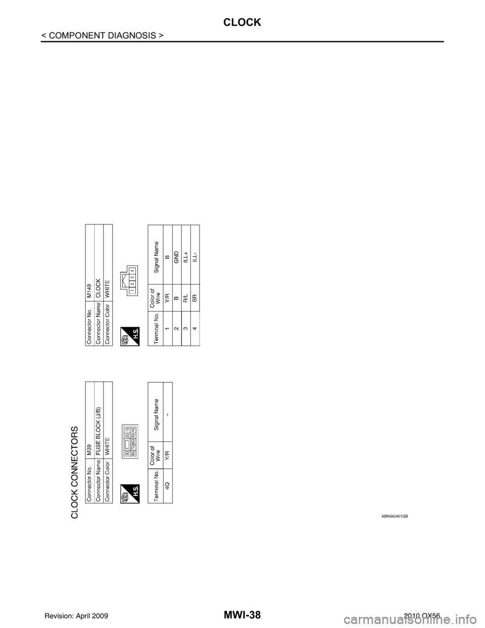
CLOCK
Wiring DiagramINFOID:0000000005146097
ALNWA0134GB
Revision: April 20092010 QX56
Page 2800 of 4210
MWI-38
< COMPONENT DIAGNOSIS >
CLOCK
ABNIA0401GB
Revision: April 20092010 QX56