Page 4056 of 4210

WCS
BCM (BODY CONTROL MODULE)WCS-57
< ECU DIAGNOSIS >
C
DE
F
G H
I
J
K L
M B A
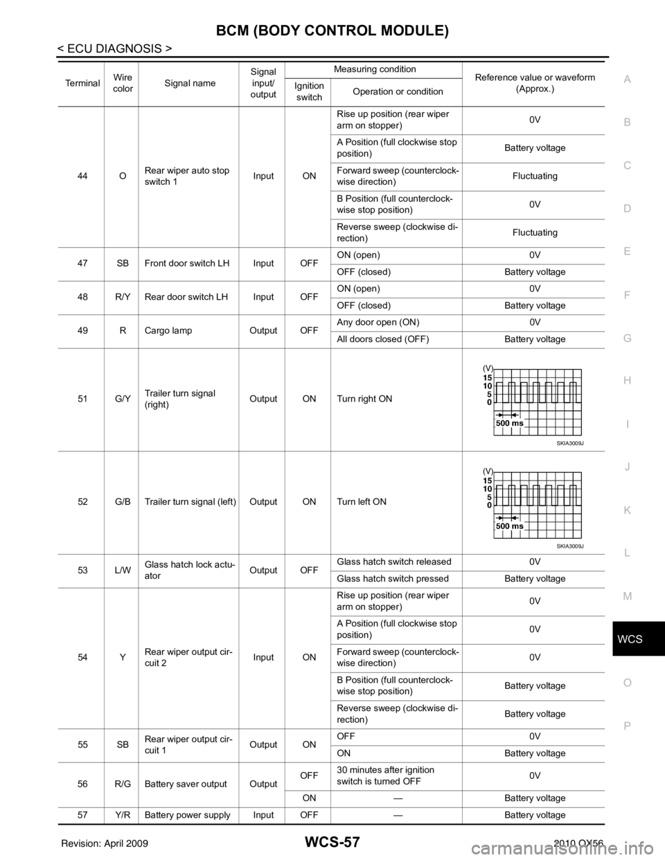
O P44 O Rear wiper auto stop
switch 1 Input ONRise up position (rear wiper
arm on stopper)
0V
A Position (full clockwise stop
position) Battery voltage
Forward sweep (counterclock-
wise direction) Fluctuating
B Position (full counterclock-
wise stop position) 0V
Reverse sweep (clockwise di-
rection) Fluctuating
47 SB Front door switch LH Input OFF ON (open)
0V
OFF (closed) Battery voltage
48 R/Y Rear door switch LH Input OFF ON (open)
0V
OFF (closed) Battery voltage
49 R Cargo lamp Output OFFAny door open (ON)
0V
All doors closed (OFF) Battery voltage
51 G/Y Trailer turn signal
(right) Output ON Turn right ON
52 G/B Trailer turn signal (left) Output ON Turn left ON
53 L/W Glass hatch lock actu-
ator
Output OFFGlass hatch switch released
0V
Glass hatch switch pressed Battery voltage
54 Y Rear wiper output cir-
cuit 2 Input ONRise up position (rear wiper
arm on stopper)
0V
A Position (full clockwise stop
position) 0V
Forward sweep (counterclock-
wise direction) 0V
B Position (full counterclock-
wise stop position) Battery voltage
Reverse sweep (clockwise di-
rection) Battery voltage
55 SB Rear wiper output cir-
cuit 1 Output ONOFF
0V
ON Battery voltage
56 R/G Battery saver output Output OFF
30 minutes after ignition
switch is turned OFF 0V
ON — Battery voltage
57 Y/R Battery power supply Input OFF —Battery voltage
Te r m i n a l
Wire
color Signal name Signal
input/
output Measuring condition
Reference value or waveform
(Approx.)
Ignition
switch Operation or condition
SKIA3009J
SKIA3009J
Revision: April 20092010 QX56
Page 4057 of 4210

WCS-58
< ECU DIAGNOSIS >
BCM (BODY CONTROL MODULE)
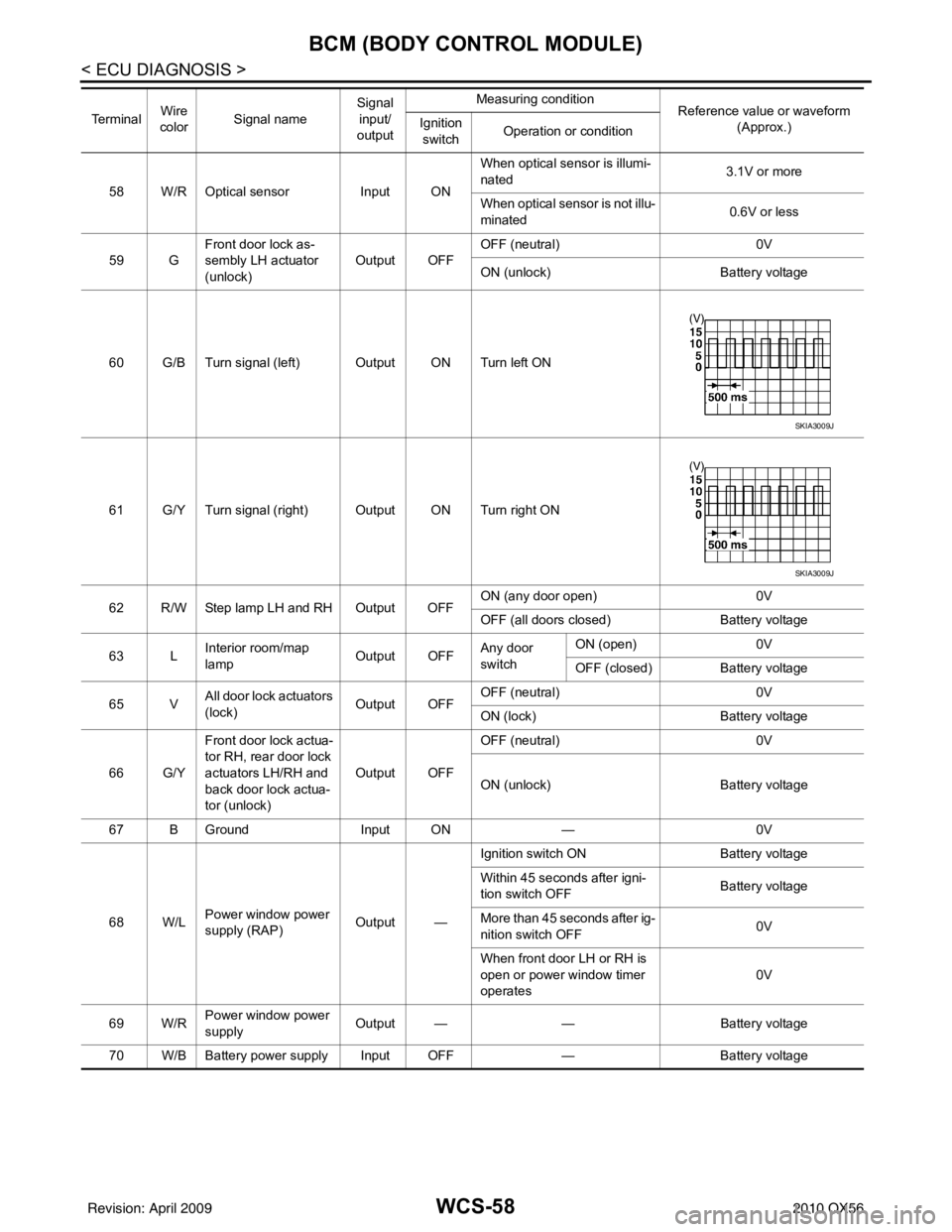
58 W/R Optical sensorInput ONWhen optical sensor is illumi-
nated
3.1V or more
When optical sensor is not illu-
minated 0.6V or less
59 G Front door lock as-
sembly LH actuator
(unlock) Output OFF
OFF (neutral)
0V
ON (unlock) Battery voltage
60 G/B Turn signal (left) Output ON Turn left ON
61 G/Y Turn signal (right) Output ON Turn right ON
62 R/W Step lamp LH and RH Output OFF ON (any door open)
0V
OFF (all doors closed) Battery voltage
63 L Interior room/map
lamp Output OFFAny door
switchON (open)
0V
OFF (closed) Battery voltage
65 V All door lock actuators
(lock) Output OFFOFF (neutral)
0V
ON (lock) Battery voltage
66 G/Y Front door lock actua-
tor RH, rear door lock
actuators LH/RH and
back door lock actua-
tor (unlock) Output OFF
OFF (neutral)
0V
ON (unlock) Battery voltage
67 B Ground Input ON—0V
68 W/L Power window power
supply (RAP) Output —Ignition switch ON
Battery voltage
Within 45 seconds after igni-
tion switch OFF Battery voltage
More than 45 seconds after ig-
nition switch OFF 0V
When front door LH or RH is
open or power window timer
operates 0V
69 W/R Power window power
supply
Output —
—Battery voltage
70 W/B Battery power supply Input OFF —Battery voltage
Te r m i n a l
Wire
color Signal name Signal
input/
output Measuring condition
Reference value or waveform
(Approx.)
Ignition
switch Operation or condition
SKIA3009J
SKIA3009J
Revision: April 20092010 QX56
Page 4058 of 4210
WCS
BCM (BODY CONTROL MODULE)WCS-59
< ECU DIAGNOSIS >
C
DE
F
G H
I
J
K L
M B A
O P
Wiring DiagramINFOID:0000000005382426
ABMWA0374GB
Revision: April 20092010 QX56
Page 4059 of 4210
WCS-60
< ECU DIAGNOSIS >
BCM (BODY CONTROL MODULE)
ABMWA0375GB
Revision: April 20092010 QX56
Page 4060 of 4210
WCS
BCM (BODY CONTROL MODULE)WCS-61
< ECU DIAGNOSIS >
C
DE
F
G H
I
J
K L
M B A
O P
AAMWA0183GB
Revision: April 20092010 QX56
Page 4061 of 4210
WCS-62
< ECU DIAGNOSIS >
BCM (BODY CONTROL MODULE)
ABMIA1059GB
Revision: April 20092010 QX56
Page 4062 of 4210
WCS
BCM (BODY CONTROL MODULE)WCS-63
< ECU DIAGNOSIS >
C
DE
F
G H
I
J
K L
M B A
O P
Fail SafeINFOID:0000000005382427
Fail-safe index
BCM performs fail-safe control when any DTC listed below is detected.
ABMIA1060GB
Revision: April 20092010 QX56
Page 4063 of 4210

WCS-64
< ECU DIAGNOSIS >
BCM (BODY CONTROL MODULE)
DTC Inspection Priority Chart
INFOID:0000000005382428
If some DTCs are displayed at the same time, perform inspections one by one based on the following priority
chart.
DTC IndexINFOID:0000000005382429
NOTE: Details of time display
• CRNT: Displays when there is a malfunction now or after returning to the normal condition until turning igni- tion switch OFF → ON again.
• 1 - 39: Displayed if any previous malfunction is present when current condition is normal. It increases like 1
→ 2 → 3...38 → 39 after returning to the normal condition whenever ignition switch OFF → ON. The counter
remains at 39 even if the number of cycles exceeds it. It is counted from 1 again when turning ignition switch
OFF → ON after returning to the normal condition if the malfunction is detected again.
Display contents of CONS ULTFail-safe Cancellation
U1000: CAN COMM CIRCUIT I nhibit engine crankingWhen the BCM re-establishes communication with the other mod-
ules.
Priority
DTC
1 • U1000: CAN COMM CIRCUIT
2 • B2190: NATS ANTENNA AMP
• B2191: DIFFERENCE OF KEY
• B2192: ID DISCORD BCM-ECM
• B2193: CHAIN OF BCM-ECM
• B2013: STRG COMM 1
• B2552: INTELLIGENT KEY
• B2590: NATS MALFUNCTION
3 • C1729: VHCL SPEED SIG ERR
• C1735: IGNITION SIGNAL
4 • C1708: [NO DATA] FL
• C1709: [NO DATA] FR
• C1710: [NO DATA] RR
• C1711: [NO DATA] RL
• C1712: [CHECKSUM ERR] FL
• C1713: [CHECKSUM ERR] FR
• C1714: [CHECKSUM ERR] RR
• C1715: [CHECKSUM ERR] RL
• C1716: [PRESSDATA ERR] FL
• C1717: [PRESSDATA ERR] FR
• C1718: [PRESSDATA ERR] RR
• C1719: [PRESSDATA ERR] RL
• C1720: [CODE ERR] FL
• C1721: [CODE ERR] FR
• C1722: [CODE ERR] RR
• C1723: [CODE ERR] RL
• C1724: [BATT VOLT LOW] FL
• C1725: [BATT VOLT LOW] FR
• C1726: [BATT VOLT LOW] RR
• C1727: [BATT VOLT LOW] RL
CONSULT display
Fail-safeIntelligent Key
warning lamp ON Tire pressure
monitor warning lamp ON Reference page
No DTC is detected.
further testing
may be required. ————
U1000: CAN COMM CIRCUIT ———BCS-32
B2190: NATS ANTENNA AMP ———SEC-31
Revision: April 20092010 QX56