2010 INFINITI QX56 ECU
[x] Cancel search: ECUPage 4103 of 4210
WT-34
< ECU DIAGNOSIS >
BCM (BODY CONTROL MODULE)
NOTE:
Before performing the self-diagnosis, be sure to register the ID or else the actual malfunction location may be different from that dis-
played on CONSULT-III.
Self-Diagnosis (Without CONSULT-III)INFOID:0000000005148233
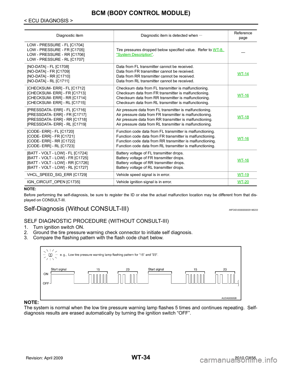
SELF DIAGNOSTIC PROCEDURE (WITHOUT CONSULT-III)
1. Turn ignition switch ON.
2. Ground the tire pressure warning check connector to initiate self diagnosis.
3. Compare the flashing pattern with the flash code chart below.
NOTE:
The system is normal when the low tire pressure warni ng lamp flashes 5 times and continues repeating. Self-
diagnosis results are erased automatically by turning the ignition switch “OFF”.
Diagnostic item Diagnostic item is detected when ··· Reference
page
LOW - PRESSURE - FL [C1704]
LOW - PRESSURE - FR [C1705]
LOW - PRESSURE - RR [C1706]
LOW - PRESSURE - RL [C1707] Tire pressures dropped below specified value. Refer to WT-8,
"System Description".
—
[NO-DATA] - FL [C1708]
[NO-DATA] - FR [C1709]
[NO-DATA] - RR [C1710]
[NO-DATA] - RL [C1711] Data from FL transmitter cannot be received.
Data from FR transmitter cannot be received.
Data from RR transmitter cannot be received.
Data from RL transmitter cannot be received.
WT-14
[CHECKSUM- ERR] - FL [C1712]
[CHECKSUM- ERR] - FR [C1713]
[CHECKSUM- ERR] - RR [C1714]
[CHECKSUM- ERR] - RL [C1715]Checksum data from FL transmitter is malfunctioning.
Checksum data from FR transmitter is malfunctioning.
Checksum data from RR transmitter is malfunctioning.
Checksum data from RL transmitter is malfunctioning.
WT-16
[PRESSDATA- ERR] - FL [C1716]
[PRESSDATA- ERR] - FR [C1717]
[PRESSDATA- ERR] - RR [C1718]
[PRESSDATA- ERR] - RL [C1719]Air pressure data from FL transmitter is malfunctioning.
Air pressure data from FR transmitter is malfunctioning.
Air pressure data from RR transmitter is malfunctioning.
Air pressure data from RL transmitter is malfunctioning.
WT-18
[CODE- ERR] - FL [C1720]
[CODE- ERR] - FR [C1721]
[CODE- ERR] - RR [C1722]
[CODE- ERR] - RL [C1723]Function code data from FL transmitter is malfunctioning.
Function code data from FR transmitter is malfunctioning.
Function code data from RR transmitter is malfunctioning.
Function code data from RL transmitter is malfunctioning.
WT-16
[BATT - VOLT - LOW] - FL [C1724]
[BATT - VOLT - LOW] - FR [C1725]
[BATT - VOLT - LOW] - RR [C1726]
[BATT - VOLT - LOW] - RL [C1727]Battery voltage of FL transmitter drops.
Battery voltage of FR transmitter drops.
Battery voltage of RR transmitter drops.
Battery voltage of RL transmitter drops.
WT-16
VHCL_SPEED_SIG_ERR [C1729]
Vehicle speed signal is in error. WT-19
IGN_CIRCUIT_OPEN [C1735]Vehicle ignition signal is in error. WT-20
ALEIA0050GB
Revision: April 20092010 QX56
Page 4104 of 4210
BCM (BODY CONTROL MODULE)WT-35
< ECU DIAGNOSIS >
C
DF
G H
I
J
K L
M A
B
WT
N
O P
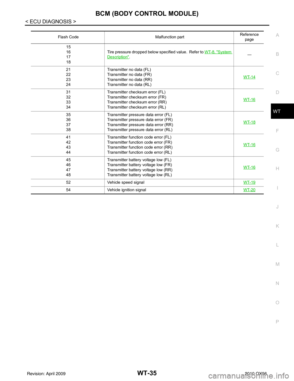
Flash Code Malfunction partReference
page
15
16
17
18 Tire pressure dropped below specified value. Refer to
WT-8, "
System
Description". —
21
22
23
24 Transmitter no data (FL)
Transmitter no data (FR)
Transmitter no data (RR)
Transmitter no data (RL)
WT-14
31
32
33
34Transmitter chec
ksum error (FL)
Transmitter chec ksum error (FR)
Transmitter chec ksum error (RR)
Transmitter chec ksum error (RL) WT-16
35
36
37
38Transmitter pressure data error (FL)
Transmitter pressure data error (FR)
Transmitter pressure data error (RR)
Transmitter pressure data error (RL)
WT-18
41
42
43
44Transmitter function
code error (FL)
Transmitter function code error (FR)
Transmitter function code error (RR)
Transmitter function code error (RL) WT-16
45
46
47
48Transmitter battery voltage low (FL)
Transmitter battery voltage low (FR)
Transmitter battery voltage low (RR)
Transmitter battery voltage low (RL)
WT-16
52
Vehicle speed signal WT-19
54Vehicle ignition signal WT-20
Revision: April 20092010 QX56
Page 4122 of 4210
WW-1
DRIVER CONTROLS
C
DE
F
G H
I
J
K
M
SECTION WW
A
B
WW
N
O P
CONTENTS
WIPER & WASHER
BASIC INSPECTION ....... .............................3
DIAGNOSIS AND REPAIR WORKFLOW ..... .....3
Work Flow ........................................................... ......3
FUNCTION DIAGNOSIS ...............................4
FRONT WIPER AND WASHER SYSTEM ..... .....4
System Diagram .................................................. ......4
System Description ...................................................4
Component Parts Location ........................................7
Component Description ............................................7
REAR WIPER AND WASHER SYSTEM ............8
System Diagram .................................................. ......8
System Description ...................................................8
Component Parts Location ......................................10
Component Description ..........................................10
DIAGNOSIS SYSTEM (BCM) ............................11
COMMON ITEM ..................................................... ....11
COMMON ITEM : CONSULT-III Function (BCM -
COMMON ITEM) .....................................................
11
WIPER ................................................................... ....11
WIPER : CONSULT-III Function (BCM - WIPER) ....12
DIAGNOSIS SYSTEM (IPDM E/R) .....................13
Diagnosis Description ......................................... ....13
CONSULT - III Function (IPDM E/R) .......................15
COMPONENT DIAGNOSIS .........................18
WIPER AND WASHER FUSE ........................ ....18
Description .......................................................... ....18
Diagnosis Procedure ...............................................18
FRONT WIPER MOTOR LO CIRCUIT ...............19
Component Function Check ................................ ....19
Diagnosis Procedure ...............................................19
FRONT WIPER MOTOR HI CIRCUIT ................21
Component Function Check ................................ ....21
Diagnosis Procedure ...............................................21
FRONT WIPER AUTO STOP SIGNAL CIR-
CUIT ..................................................................
23
Component Function Check ....................................23
Diagnosis Procedure ...............................................23
FRONT WIPER MOTOR GROUND CIRCUIT ...25
Diagnosis Procedure ...............................................25
WASHER SWITCH ............................................26
Description ...............................................................26
Component Inspection .............................................26
REAR WIPER MOTOR CIRCUIT ......................28
Component Function Check ....................................28
Diagnosis Procedure ...............................................28
REAR WIPER AUTO STOP SIGNAL CIRCUIT
...
30
Component Function Check ................................ ....30
Diagnosis Procedure ...............................................30
FRONT WIPER AND WASHER SYSTEM ........31
Wiring Diagram ........................................................31
REAR WIPER AND WASHER SYSTEM ..........35
Wiring Diagram ........................................................35
ECU DIAGNOSIS .........................................41
BCM (BODY CONTROL MODULE) .................41
Reference Value .................................................. ....41
Terminal Layout .......................................................44
Physical Values ................................................... ....44
Wiring Diagram ........................................................50
Fail Safe ..................................................................54
DTC Inspection Priority Chart ...............................55
DTC Index ...............................................................55
IPDM E/R (INTELLIGENT POWER DISTRI-
BUTION MODULE ENGINE ROOM) ................
57
Revision: April 20092010 QX56
Page 4132 of 4210
DIAGNOSIS SYSTEM (BCM)WW-11
< FUNCTION DIAGNOSIS >
C
DE
F
G H
I
J
K
M A
B
WW
N
O P
DIAGNOSIS SYSTEM (BCM)
COMMON ITEM
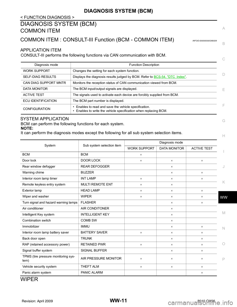
COMMON ITEM : CONSULT-III Fu nction (BCM - COMMON ITEM)INFOID:0000000005369209
APPLICATION ITEM
CONSULT-III performs the following functions via CAN communication with BCM.
SYSTEM APPLICATION
BCM can perform the following functions for each system.
NOTE:
It can perform the diagnosis modes except the following for all sub system selection items.
WIPER
Diagnosis mode Function Description
WORK SUPPORT Changes the setting for each system function.
SELF-DIAG RESULTS Displays the diagnosis results judged by BCM. Refer to BCS-54, "
DTCIndex".
CAN DIAG SUPPORT MNTR Monitors the reception status of CAN communication viewed from BCM.
DATA MONITOR The BCM input/output signals are displayed.
ACTIVE TEST The signals used to activate each device are forcibly supplied from BCM.
ECU IDENTIFICATION The BCM pa rt number is displayed.
CONFIGURATION • Enables to read and save the vehicle specification.
• Enables to write the vehicle specification when replacing BCM.
System
Sub system selection item Diagnosis mode
WORK SUPPORT DATA MONITOR ACTIVE TEST
BCM BCM ×
Door lock DOOR LOCK ×××
Rear window defogger REAR DEFOGGER ×
Warning chime BUZZER ××
Interior room lamp timer INT LAMP ×××
Remote keyless entry system MULTI REMOTE ENT ××
Exterior lamp HEAD LAMP ×××
Wiper and washer WIPER ×××
Turn signal and hazard warning lamps FLASHER ××
Air conditioner AIR CONDITONER ×
Intelligent Key system INTELLIGENT KEY ×
Combination switch COMB SW ×
Immobilizer IMMU ××
Interior room lamp battery saver BATTERY SAVER ×××
Back door open TRUNK ××
RAP (retained accessory power) RETAINED PWR ×××
Signal buffer system SIGNAL BUFFER ××
TPMS (tire pressure monitoring sys-
tem) AIR PRESSURE MONITOR
×××
Vehicle security system THEFT ALM ×××
Panic alarm system PANIC ALARM ×
Revision: April 20092010 QX56
Page 4162 of 4210
BCM (BODY CONTROL MODULE)WW-41
< ECU DIAGNOSIS >
C
DE
F
G H
I
J
K
M A
B
WW
N
O P
ECU DIAGNOSIS
BCM (BODY CONTROL MODULE)
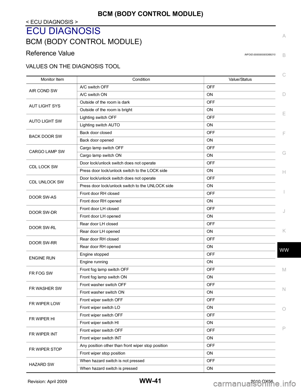
Reference ValueINFOID:0000000005369215
VALUES ON THE DIAGNOSIS TOOL
Monitor Item Condition Value/Status
AIR COND SW A/C switch OFF
OFF
A/C switch ON ON
AUT LIGHT SYS Outside of the room is dark
OFF
Outside of the room is bright ON
AUTO LIGHT SW Lighting switch OFF
OFF
Lighting switch AUTO ON
BACK DOOR SW Back door closed
OFF
Back door opened ON
CARGO LAMP SW Cargo lamp switch OFF
OFF
Cargo lamp switch ON ON
CDL LOCK SW Door lock/unlock switch does not operate
OFF
Press door lock/unlock switch to the LOCK side ON
CDL UNLOCK SW Door lock/unlock switch does not operate
OFF
Press door lock/unlock switch to the UNLOCK side ON
DOOR SW-AS Front door RH closed
OFF
Front door RH opened ON
DOOR SW-DR Front door LH closed
OFF
Front door LH opened ON
DOOR SW-RL Rear door LH closed
OFF
Rear door LH opened ON
DOOR SW-RR Rear door RH closed
OFF
Rear door RH opened ON
ENGINE RUN Engine stopped
OFF
Engine running ON
FR FOG SW Front fog lamp switch OFF
OFF
Front fog lamp switch ON ON
FR WASHER SW Front washer switch OFF
OFF
Front washer switch ON ON
FR WIPER LOW Front wiper switch OFF
OFF
Front wiper switch LO ON
FR WIPER HI Front wiper switch OFF
OFF
Front wiper switch HI ON
FR WIPER INT Front wiper switch OFF
OFF
Front wiper switch INT ON
FR WIPER STOP Any position other than front wiper stop position
OFF
Front wiper stop position ON
HAZARD SW When hazard switch is not pressed
OFF
When hazard switch is pressed ON
Revision: April 20092010 QX56
Page 4163 of 4210

WW-42
< ECU DIAGNOSIS >
BCM (BODY CONTROL MODULE)
LIGHT SW 1STLighting switch OFF OFF
Lighting switch 1st
ON
HEAD LAMP SW1 Headlamp switch OFF
OFF
Headlamp switch 1st ON
HEAD LAMP SW2 Headlamp switch OFF
OFF
Headlamp switch 1st ON
HI BEAM SW High beam switch OFF
OFF
High beam switch HI ON
IGN ON SW Ignition switch OFF or ACC
OFF
Ignition switch ON ON
IGN SW CAN Ignition switch OFF or ACC
OFF
Ignition switch ON ON
INT VOLUME Wiper intermittent dial is in a dial position 1 - 7 1 - 7
I-KEY LOCK LOCK button of Intelligent Key is not pressed
OFF
LOCK button of Intelligent Key is pressed ON
I-KEY UNLOCK UNLOCK button of Intelligent Key is not pressed
OFF
UNLOCK button of Intelligent Key is pressed ON
KEY CYL LK-SW Door key cylinder LOCK position
ON
Door key cylinder other than LOCK position OF
KEY CYL UN-SW Door key cylinder UNLOCK position
ON
Door key cylinder other than UNLOCK position ON
KEY ON SW Mechanical key is removed from key cylinder
OFF
Mechanical key is inserted to key cylinder ON
OIL PRESS SW • Ignition switch OFF or ACC
• Engine running
OFF
Ignition switch ON ON
OPTICAL SENSOR Bright outside of the vehicle
Close to 5V
Dark outside of the vehicle Close to 0V
PASSING SW Other than lighting switch PASS
OFF
Lighting switch PASS ON
PUSH SW Return to ignition switch to LOCK position
OFF
Press ignition switch ON
REAR DEF SW Rear window defogger switch OFF
OFF
Rear window defogger switch ON ON
RR WASHER SW Rear washer switch OFF
OFF
Rear washer switch ON ON
RR WIPER INT Rear wiper switch OFF
OFF
Rear wiper switch INT ON
RR WIPER ON Rear wiper switch OFF
OFF
Rear wiper switch ON ON
RR WIPER STOP Rear wiper stop position
OFF
Other than rear wiper stop position ON
RR WIPER STP2 Rear wiper stop position
OFF
Other than rear wiper stop position ON
Monitor Item
Condition Value/Status
Revision: April 20092010 QX56
Page 4164 of 4210
BCM (BODY CONTROL MODULE)WW-43
< ECU DIAGNOSIS >
C
DE
F
G H
I
J
K
M A
B
WW
N
O P
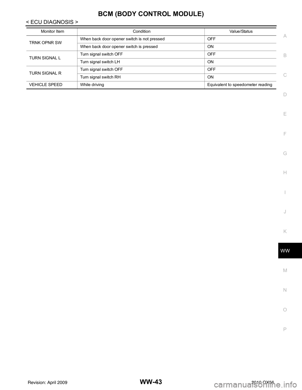
TRNK OPNR SW When back door opener switch is not pressed OFF
When back door opener switch is pressed
ON
TURN SIGNAL L Turn signal switch OFF
OFF
Turn signal switch LH ON
TURN SIGNAL R Turn signal switch OFF
OFF
Turn signal switch RH ON
VEHICLE SPEED While driving Equivalent to speedo meter reading
Monitor Item
Condition Value/Status
Revision: April 20092010 QX56
Page 4165 of 4210
WW-44
< ECU DIAGNOSIS >
BCM (BODY CONTROL MODULE)
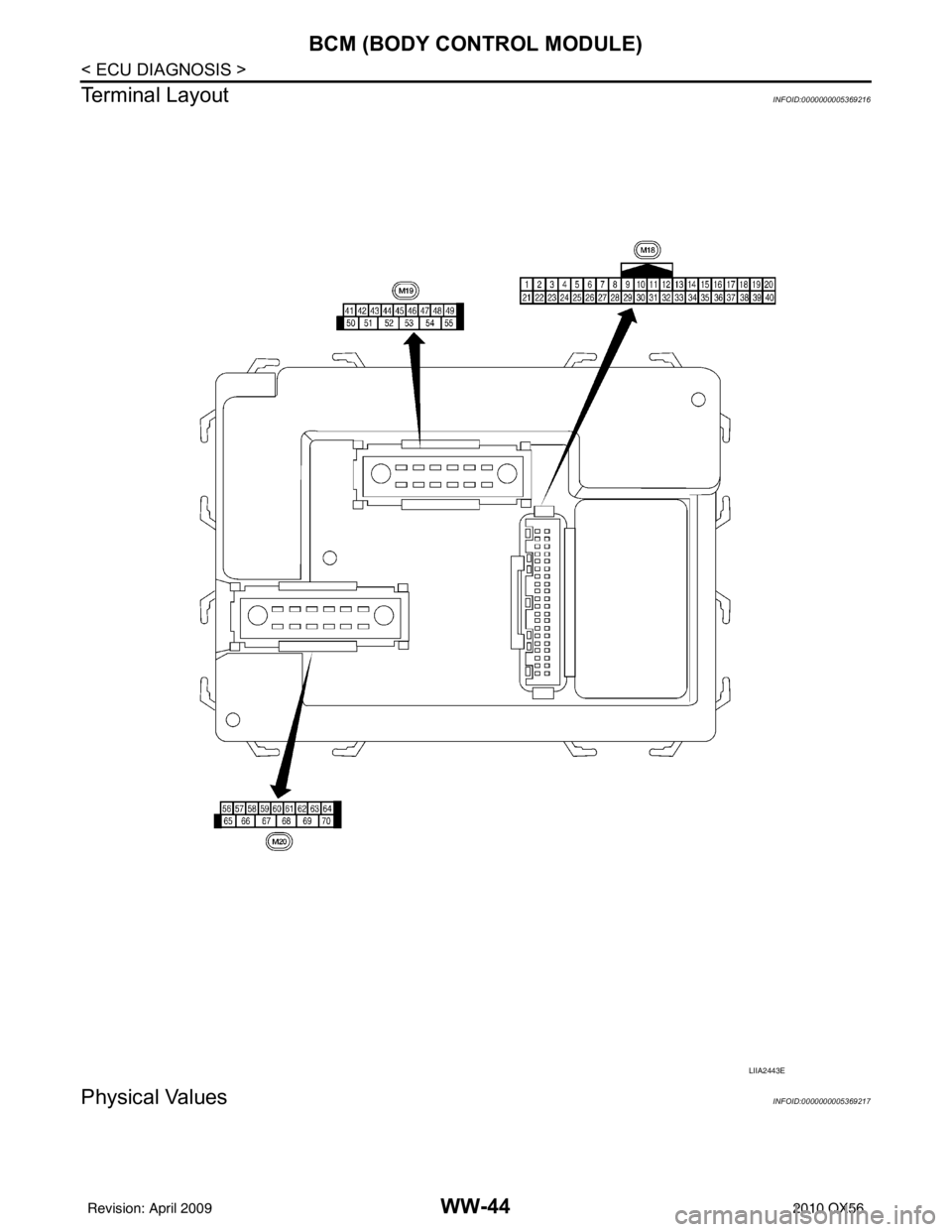
Terminal Layout
INFOID:0000000005369216
Physical ValuesINFOID:0000000005369217
LIIA2443E
Revision: April 20092010 QX56