2010 INFINITI QX56 ignition
[x] Cancel search: ignitionPage 2023 of 4210
OPTICAL SENSOREXL-47
< COMPONENT DIAGNOSIS >
C
DE
F
G H
I
J
K
M A
B
EXL
N
O P
OPTICAL SENSOR
DescriptionINFOID:0000000005146657
The optical sensor converts the outside brightness (lux) to voltage and transmits the optical sensor signal to
the BCM.
Component Function CheckINFOID:0000000005146658
1.CHECK OPTICAL SENSOR SIGNAL BY CONSULT-III
CONSULT-III
1. Turn the ignition switch ON.
2. Select "OPTICAL SENSOR" of BC M (HEAD LAMP) DATA MONITOR item.
3. Turn the lighting switch to AUTO.
4. With the optical sensor illuminat ing, check the monitor status.
*: Illuminates the optical sensor. The value may be less than the standard value if brightness is weak.
Is the item status normal?
YES >> Optical sensor is normal.
NO >> Refer to EXL-47, "
Diagnosis Procedure".
Diagnosis ProcedureINFOID:0000000005146659
Regarding Wiring Diagram information, refer to EXL-62, "Wiring Diagram".
1.CHECK OPTICAL SENSOR GROUND CIRCUIT
1. Turn the ignition switch OFF.
2. Disconnect BCM connector M18 and optical sensor connector M302.
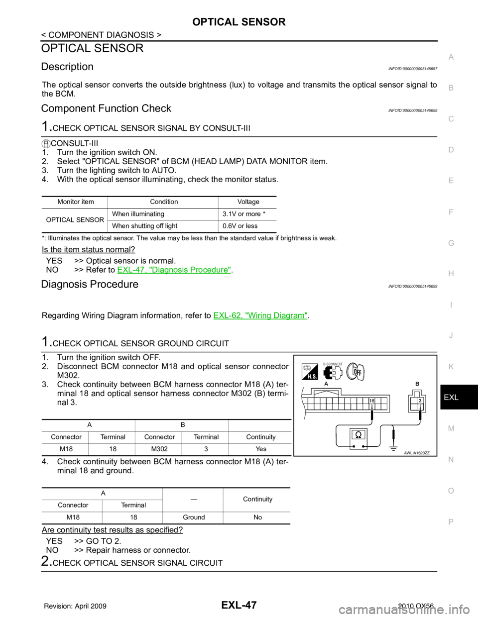
3. Check continuity between BCM harness connector M18 (A) ter-
minal 18 and optical sensor harness connector M302 (B) termi-
nal 3.
4. Check continuity between BCM harness connector M18 (A) ter- minal 18 and ground.
Are continuity test results as specified?
YES >> GO TO 2.
NO >> Repair harness or connector.
2.CHECK OPTICAL SENSOR SIGNAL CIRCUIT
Monitor item ConditionVoltage
OPTICAL SENSOR When illuminating
3.1V or more *
When shutting off light 0.6V or less
AB
Connector Terminal Connector Terminal Continuity M181 8M3023 Y es
A —Contin u it y
Connector Terminal
M18 18Ground No
AWLIA1620ZZ
Revision: April 20092010 QX56
Page 2025 of 4210
HEADLAMP AIMING SWITCHEXL-49
< COMPONENT DIAGNOSIS >
C
DE
F
G H
I
J
K
M A
B
EXL
N
O P
HEADLAMP AIMING SWITCH
DescriptionINFOID:0000000005146660
The manual headlamp aiming system uses a headlamp aiming switch to adjust the axis of the headlamp aim-
ing motor. The headlamp aiming switch has four settings, each with a different resistance value. The head-
lamp aiming motor adjusts to the proper axis based off the position of the headlamp aiming switch.
Diagnosis Procedure - Without Daytime Light SystemINFOID:0000000005146661
Regarding Wiring Diagram information, refer to EXL-69, "Wiring Diagram".
1.CHECK HEADLAMP AIMING SWITCH SIGNAL FOR OPEN OR SHORT CIRCUIT
1. Turn ignition switch OFF.
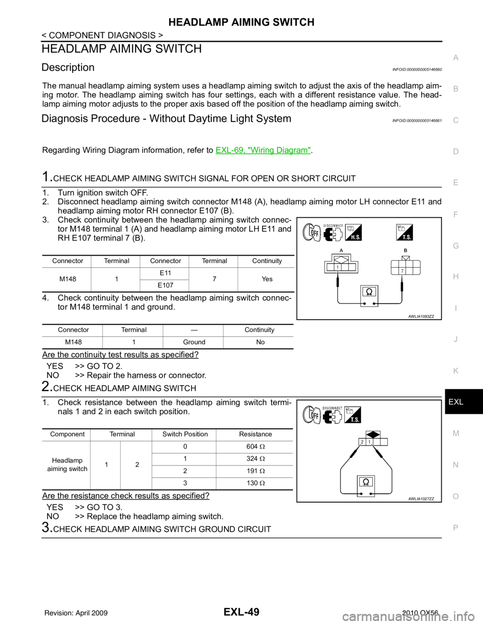
2. Disconnect headlamp aiming switch connector M148 (A), headlamp aiming motor LH connector E11 and
headlamp aiming motor RH connector E107 (B).
3. Check continuity between the headlamp aiming switch connec-
tor M148 terminal 1 (A) and headlamp aiming motor LH E11 and
RH E107 terminal 7 (B).
4. Check continuity between the headlamp aiming switch connec- tor M148 terminal 1 and ground.
Are the continuity test results as specified?
YES >> GO TO 2.
NO >> Repair the harness or connector.
2.CHECK HEADLAMP AIMING SWITCH
1. Check resistance between the headlamp aiming switch termi- nals 1 and 2 in each switch position.
Are the resistance check results as specified?
YES >> GO TO 3.
NO >> Replace the headlamp aiming switch.
3.CHECK HEADLAMP AIMING SWITCH GROUND CIRCUIT
Connector Terminal Connector Terminal Continuity
M148 1E11
7Y es
E107
Connector Terminal —Continuity
M148 1Ground No
AWLIA1093ZZ
Component Terminal Switch Position Resistance
Headlamp
aiming switch 12 06
04 Ω
13 24 Ω
21 91 Ω
31 30 Ω
AWLIA1027ZZ
Revision: April 20092010 QX56
Page 2026 of 4210
EXL-50
< COMPONENT DIAGNOSIS >
HEADLAMP AIMING SWITCH
1. Turn the ignition switch OFF.
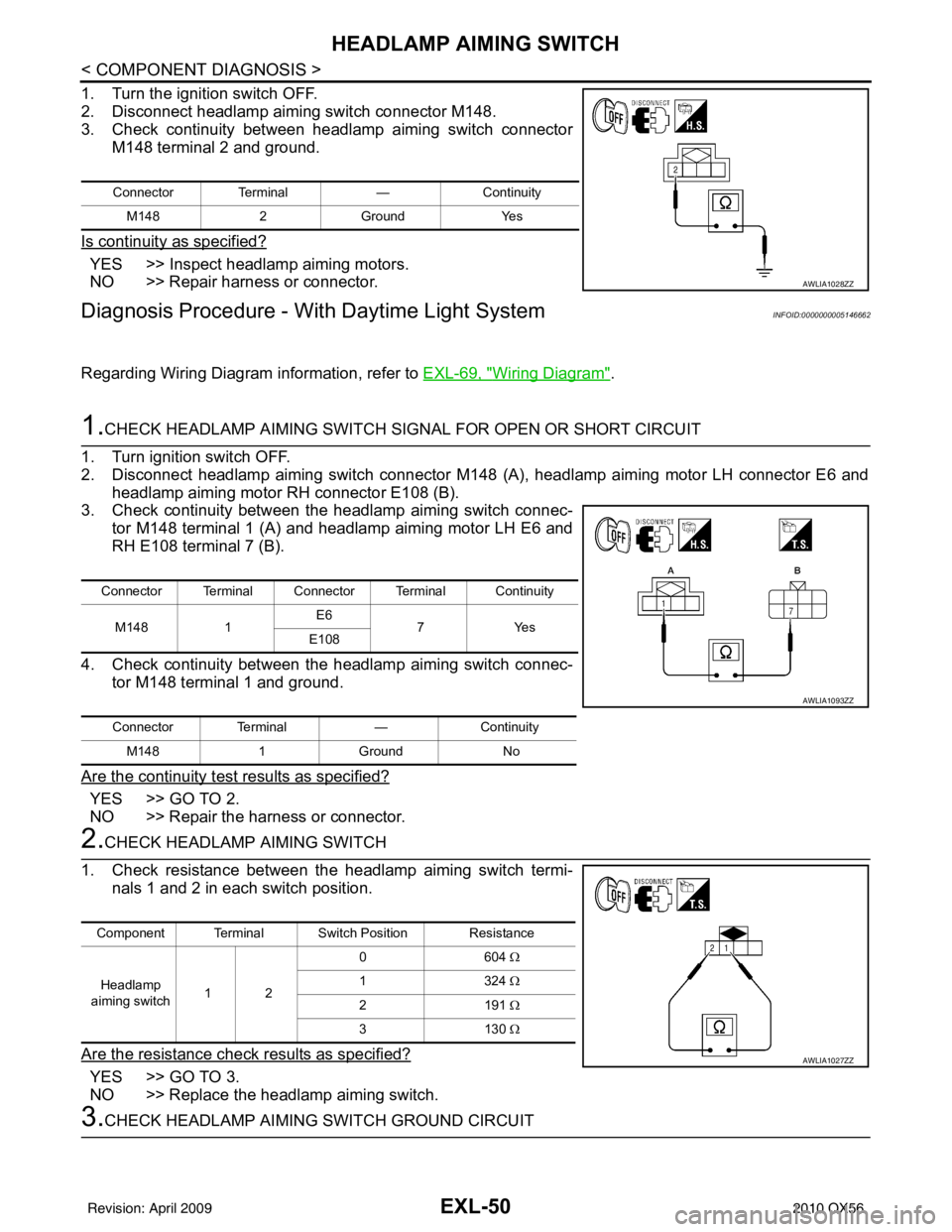
2. Disconnect headlamp aiming switch connector M148.
3. Check continuity between headlamp aiming switch connectorM148 terminal 2 and ground.
Is continuity as specified?
YES >> Inspect headlamp aiming motors.
NO >> Repair harness or connector.
Diagnosis Procedure - With Daytime Light SystemINFOID:0000000005146662
Regarding Wiring Diagram information, refer to EXL-69, "Wiring Diagram".
1.CHECK HEADLAMP AIMING SWITCH SIGNAL FOR OPEN OR SHORT CIRCUIT
1. Turn ignition switch OFF.
2. Disconnect headlamp aiming switch connector M148 (A), headlamp aiming motor LH connector E6 and headlamp aiming motor RH connector E108 (B).
3. Check continuity between the headlamp aiming switch connec-
tor M148 terminal 1 (A) and headlamp aiming motor LH E6 and
RH E108 terminal 7 (B).
4. Check continuity between the headlamp aiming switch connec- tor M148 terminal 1 and ground.
Are the continuity test results as specified?
YES >> GO TO 2.
NO >> Repair the harness or connector.
2.CHECK HEADLAMP AIMING SWITCH
1. Check resistance between the headlamp aiming switch termi- nals 1 and 2 in each switch position.
Are the resistance check results as specified?
YES >> GO TO 3.
NO >> Replace the headlamp aiming switch.
3.CHECK HEADLAMP AIMING SWITCH GROUND CIRCUIT
Connector Terminal —Continuity
M148 2Ground Yes
AWLIA1028ZZ
Connector Terminal Connector Terminal Continuity
M148 1E6
7Y es
E108
Connector Terminal —Continuity
M148 1Ground No
AWLIA1093ZZ
Component Terminal Switch Position Resistance
Headlamp
aiming switch 12 06
04 Ω
13 24 Ω
21 91 Ω
31 30 Ω
AWLIA1027ZZ
Revision: April 20092010 QX56
Page 2027 of 4210
HEADLAMP AIMING SWITCHEXL-51
< COMPONENT DIAGNOSIS >
C
DE
F
G H
I
J
K
M A
B
EXL
N
O P
1. Turn the ignition switch OFF.
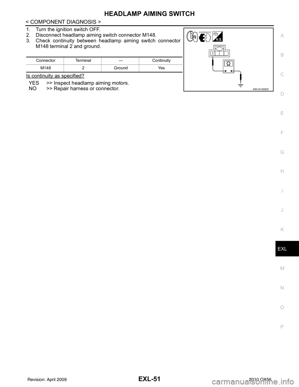
2. Disconnect headlamp aiming switch connector M148.
3. Check continuity between headlamp aiming switch connector M148 terminal 2 and ground.
Is continuity as specified?
YES >> Inspect headlamp aiming motors.
NO >> Repair harness or connector.
Connector Terminal —Continuity
M148 2Ground Yes
AWLIA1028ZZ
Revision: April 20092010 QX56
Page 2083 of 4210

BCM (BODY CONTROL MODULE)EXL-107
< ECU DIAGNOSIS >
C
DE
F
G H
I
J
K
M A
B
EXL
N
O P
LIGHT SW 1ST Lighting switch OFF OFF
Lighting switch 1st
ON
HEAD LAMP SW1 Headlamp switch OFF
OFF
Headlamp switch 1st ON
HEAD LAMP SW2 Headlamp switch OFF
OFF
Headlamp switch 1st ON
HI BEAM SW High beam switch OFF
OFF
High beam switch HI ON
IGN ON SW Ignition switch OFF or ACC
OFF
Ignition switch ON ON
IGN SW CAN Ignition switch OFF or ACC
OFF
Ignition switch ON ON
INT VOLUME Wiper intermittent dial is in a dial position 1 - 7 1 - 7
I-KEY LOCK LOCK button of Intelligent Key is not pressed
OFF
LOCK button of Intelligent Key is pressed ON
I-KEY UNLOCK UNLOCK button of Intelligent Key is not pressed
OFF
UNLOCK button of Intelligent Key is pressed ON
KEY CYL LK-SW Door key cylinder LOCK position
ON
Door key cylinder other than LOCK position OF
KEY CYL UN-SW Door key cylinder UNLOCK position
ON
Door key cylinder other than UNLOCK position ON
KEY ON SW Mechanical key is removed from key cylinder
OFF
Mechanical key is inserted to key cylinder ON
OIL PRESS SW • Ignition switch OFF or ACC
• Engine running
OFF
Ignition switch ON ON
OPTICAL SENSOR Bright outside of the vehicle
Close to 5V
Dark outside of the vehicle Close to 0V
PASSING SW Other than lighting switch PASS
OFF
Lighting switch PASS ON
PUSH SW Return to ignition switch to LOCK position
OFF
Press ignition switch ON
REAR DEF SW Rear window defogger switch OFF
OFF
Rear window defogger switch ON ON
RR WASHER SW Rear washer switch OFF
OFF
Rear washer switch ON ON
RR WIPER INT Rear wiper switch OFF
OFF
Rear wiper switch INT ON
RR WIPER ON Rear wiper switch OFF
OFF
Rear wiper switch ON ON
RR WIPER STOP Rear wiper stop position
OFF
Other than rear wiper stop position ON
RR WIPER STP2 Rear wiper stop position
OFF
Other than rear wiper stop position ON
Monitor Item
Condition Value/Status
Revision: April 20092010 QX56
Page 2086 of 4210
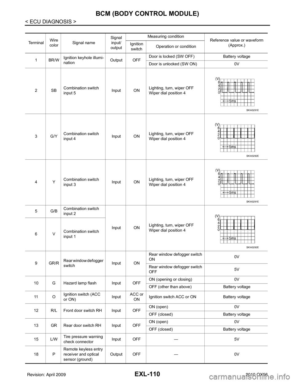
EXL-110
< ECU DIAGNOSIS >
BCM (BODY CONTROL MODULE)
Te r m i n a lWire
color Signal name Signal
input/
output Measuring condition
Reference value or waveform
(Approx.)
Ignition
switch Operation or condition
1BR/W Ignition keyhole illumi-
nation Output OFFDoor is locked (SW OFF)
Battery voltage
Door is unlocked (SW ON) 0V
2SB Combination switch
input 5 Input ON
Lighting, turn, wiper OFF
Wiper dial position 4
3G/Y Combination switch
input 4 Input ONLighting, turn, wiper OFF
Wiper dial position 4
4Y Combination switch
input 3 Input ON
Lighting, turn, wiper OFF
Wiper dial position 4
5G/B Combination switch
input 2
Input ONLighting, turn, wiper OFF
Wiper dial position 4
6V Combination switch
input 1
9GR/R Rear window defogger
switch
Input ONRear window defogger switch
ON
0V
Rear window defogger switch
OFF 5V
10 G Hazard lamp flash Input OFF ON (opening or closing)
0V
OFF (other than above) Battery voltage
11 O Ignition switch (ACC
or ON)
InputACC or
ON Ignition switch ACC or ON
Battery voltage
12 R/L Front door switch RH Input OFF ON (open)
0V
OFF (closed) Battery voltage
13 GR Rear door switch RH Input OFF ON (open)
0V
OFF (closed) Battery voltage
15 L/W Tire pressure warning
check connector
Input OFF
—5V
18 P Remote keyless entry
receiver and optical
sensor (ground)
Output OFF
—0V
SKIA5291E
SKIA5292E
SKIA5291E
SKIA5292E
Revision: April 20092010 QX56
Page 2087 of 4210
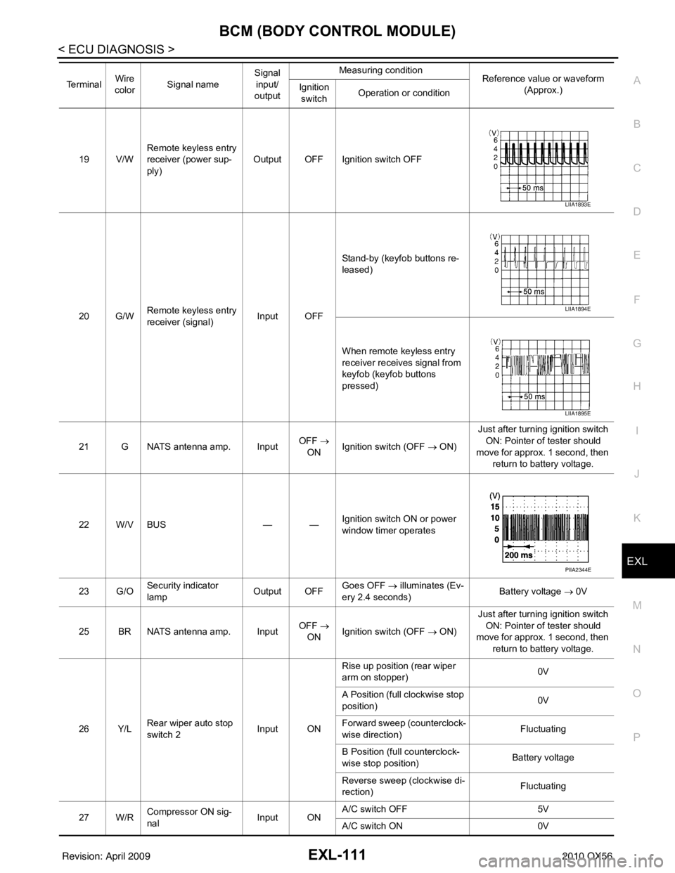
BCM (BODY CONTROL MODULE)EXL-111
< ECU DIAGNOSIS >
C
DE
F
G H
I
J
K
M A
B
EXL
N
O P
19 V/W Remote keyless entry
receiver (power sup-
ply) Output OFF Ignition switch OFF
20 G/W Remote keyless entry
receiver (signal) Input OFFStand-by (keyfob buttons re-
leased)
When remote keyless entry
receiver receives signal from
keyfob (keyfob buttons
pressed)
21 G NATS antenna amp. Input OFF
→
ON Ignition switch (OFF → ON) Just after turning ignition switch
ON: Pointer of tester should
move for approx. 1 second, then return to battery voltage.
22 W/V BUS — —Ignition switch ON or power
window timer operates
23 G/O Security indicator
lamp Output OFF
Goes OFF
→ illuminates (Ev-
ery 2.4 seconds) Battery voltage
→ 0V
25 BR NATS antenna amp. Input OFF
→
ON Ignition switch (OFF → ON) Just after turning ignition switch
ON: Pointer of tester should
move for approx. 1 second, then return to battery voltage.
26 Y/L Rear wiper auto stop
switch 2 Input ONRise up position (rear wiper
arm on stopper)
0V
A Position (full clockwise stop
position) 0V
Forward sweep (counterclock-
wise direction) Fluctuating
B Position (full counterclock-
wise stop position) Battery voltage
Reverse sweep (clockwise di-
rection) Fluctuating
27 W/R Compressor ON sig-
nal Input ONA/C switch OFF
5V
A/C switch ON 0V
Te r m i n a l
Wire
color Signal name Signal
input/
output Measuring condition
Reference value or waveform
(Approx.)
Ignition
switch Operation or condition
LIIA1893E
LIIA1894E
LIIA1895E
PIIA2344E
Revision: April 20092010 QX56
Page 2088 of 4210
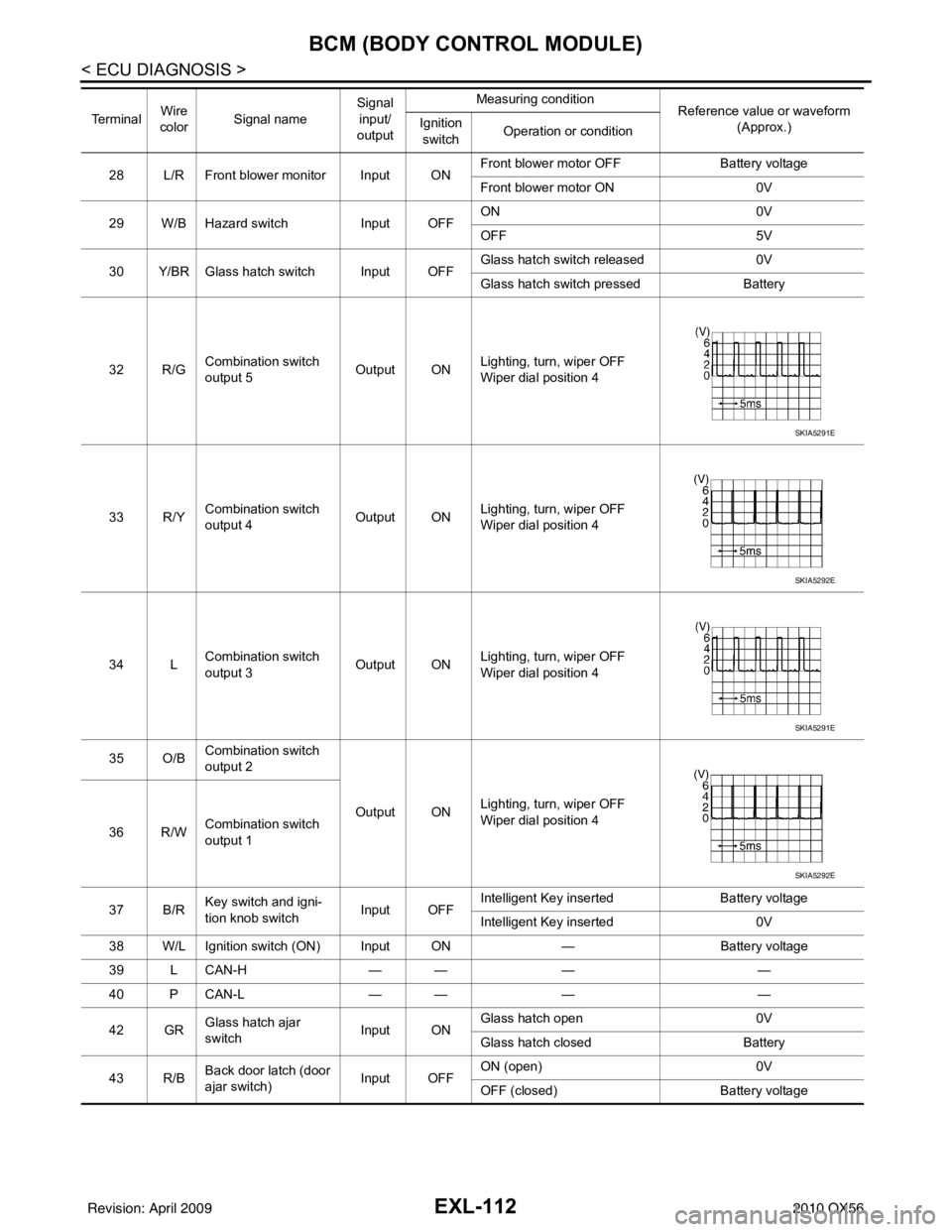
EXL-112
< ECU DIAGNOSIS >
BCM (BODY CONTROL MODULE)
28 L/R Front blower monitor Input ONFront blower motor OFF
Battery voltage
Front blower motor ON 0V
29 W/B Hazard switch Input OFFON
0V
OFF 5V
30 Y/BR Glass hatch switch Input OFF Glass hatch switch released
0V
Glass hatch switch pressed Battery
32 R/G Combination switch
output 5
Output ONLighting, turn, wiper OFF
Wiper dial position 4
33 R/Y Combination switch
output 4 Output ONLighting, turn, wiper OFF
Wiper dial position 4
34 L Combination switch
output 3 Output ON
Lighting, turn, wiper OFF
Wiper dial position 4
35 O/B Combination switch
output 2
Output ONLighting, turn, wiper OFF
Wiper dial position 4
36 R/W Combination switch
output 1
37 B/R Key switch and igni-
tion knob switch Input OFFIntelligent Key inserted
Battery voltage
Intelligent Key inserted 0V
38 W/L Ignition switch (ON) Input ON —Battery voltage
39 L CAN-H — —— —
40 P CAN-L — —— —
42 GR Glass hatch ajar
switch Input ONGlass hatch open
0V
Glass hatch closed Battery
43 R/B Back door latch (door
ajar switch) Input OFFON (open)
0V
OFF (closed) Battery voltage
Te r m i n a l
Wire
color Signal name Signal
input/
output Measuring condition
Reference value or waveform
(Approx.)
Ignition
switch Operation or condition
SKIA5291E
SKIA5292E
SKIA5291E
SKIA5292E
Revision: April 20092010 QX56