2010 INFINITI QX56 ignition
[x] Cancel search: ignitionPage 1984 of 4210

EXL-8
< FUNCTION DIAGNOSIS >
HEADLAMP
A Xenon type headlamp is adapted to the low beam headlamps. Xenon bulbs do not use a filament. Instead,
they produce light when a high voltage current is pa ssed between two tungsten electrodes through a mixture
of Xenon (an inert gas) and certain other metal halides. In addition to added lighting power, electronic control
of the power supply gives the headlamps stable quality and tone color. Following are some of the advantages
of the Xenon type headlamp.
• The light produced by the headlamps is a white color comparable to sunlight that is easy on the eyes.
• Light output is nearly double that of halogen headlamps, affording increased area of illumination.
• The light features a high relative spectral distribution at wavelengths to which the human eye is most sensi- tive. This means that even in the rain, more light is reflected back from the road surface toward the vehicle,
for added visibility.
• Power consumption is approximately 25 percent less than halogen headlamps, reducing battery load.
HIGH BEAM OPERATION/FLASH-TO-PASS OPERATION
With the combination switch (lighting and turn signal switch) in the 2ND position and placed in HIGH position,
the BCM receives input requesting the headlamp high beams to illuminate. The flash to pass feature can be
used any time and also sends a signal to the BCM. This input is communicated to the IPDM E/R via the CAN
communication lines. The CPU of the combination meter c ontrols the ON/OFF status off the HIGH BEAM indi-
cator. The CPU of the IPDM E/R controls the headlamp high relay coil which supplies power to the high beam
headlamps.
The combination meter receives a high beam request signal (ON) via the CAN communication lines and turns
the high beam indicator lamp ON.
EXTERIOR LAMP BATTERY SAVER CONTROL
With the combination switch (lighting and turn signal switch) in the 2nd position and the ignition switch is
turned from ON or ACC to OFF, the battery saver feature is activated.
Under this condition, the headlamps remain illuminated for 5 minutes unless the lighting switch position is
changed. If the lighting switch position is changed, then the headlamps are turned off.
This setting can be changed by CONSULT-III. Refer to BCS-22, "
HEADLAMP : CONSULT-III Function (BCM -
HEAD LAMP)".
Revision: April 20092010 QX56
Page 1987 of 4210

AUTO LIGHT SYSTEMEXL-11
< FUNCTION DIAGNOSIS >
C
DE
F
G H
I
J
K
M A
B
EXL
N
O P
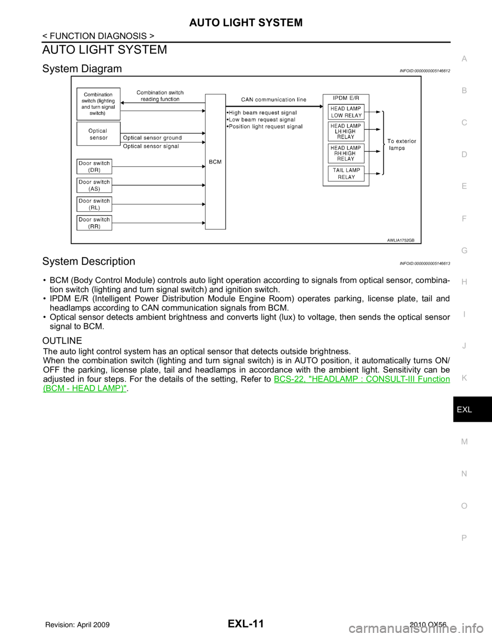
AUTO LIGHT SYSTEM
System DiagramINFOID:0000000005146612
System DescriptionINFOID:0000000005146613
• BCM (Body Control Module) controls auto light operati on according to signals from optical sensor, combina-
tion switch (lighting and turn signal switch) and ignition switch.
• IPDM E/R (Intelligent Power Distribution Module Engine Room) operates parking, license plate, tail and
headlamps according to CAN communication signals from BCM.
• Optical sensor detects ambient br ightness and converts light (lux) to voltage, then sends the optical sensor
signal to BCM.
OUTLINE
The auto light control system has an optical sensor that detects outside brightness.
When the combination switch (lighting and turn signal switch) is in AUTO position, it automatically turns ON/
OFF the parking, license plate, tail and headlamps in accordance with the ambient light. Sensitivity can be
adjusted in four steps. For the details of the setting, Refer to BCS-22, "
HEADLAMP : CONSULT-III Function
(BCM - HEAD LAMP)".
AWLIA1752GB
Revision: April 20092010 QX56
Page 1991 of 4210

TURN SIGNAL AND HAZARD WARNING LAMPSEXL-15
< FUNCTION DIAGNOSIS >
C
DE
F
G H
I
J
K
M A
B
EXL
N
O P
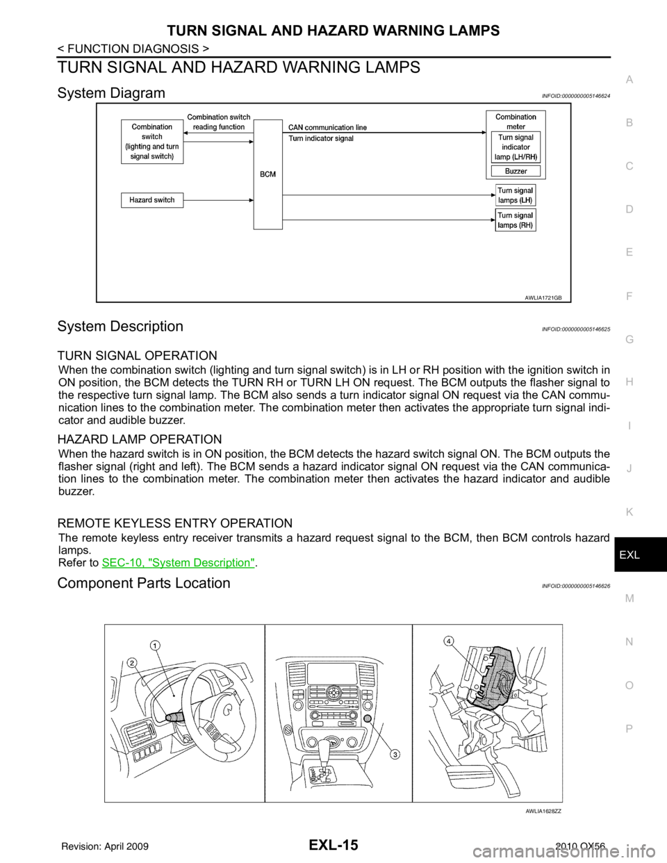
TURN SIGNAL AND HA ZARD WARNING LAMPS
System DiagramINFOID:0000000005146624
System DescriptionINFOID:0000000005146625
TURN SIGNAL OPERATION
When the combination switch (lighting and turn signal switch) is in LH or RH position with the ignition switch in
ON position, the BCM detects the TURN RH or TURN LH ON request. The BCM outputs the flasher signal to
the respective turn signal lamp. The BCM also sends a turn indicator signal ON request via the CAN commu-
nication lines to the combination meter. The combination meter then activates the appropriate turn signal indi-
cator and audible buzzer.
HAZARD LAMP OPERATION
When the hazard switch is in ON position, the BCM detects the hazard switch signal ON. The BCM outputs the
flasher signal (right and left). The BCM sends a hazar d indicator signal ON request via the CAN communica-
tion lines to the combination meter. The combinati on meter then activates the hazard indicator and audible
buzzer.
REMOTE KEYLESS ENTRY OPERATION
The remote keyless entry receiver transmits a hazard request signal to the BCM, then BCM controls hazard
lamps.
Refer to SEC-10, "
System Description".
Component Parts LocationINFOID:0000000005146626
AWLIA1721GB
AWLIA1628ZZ
Revision: April 20092010 QX56
Page 1993 of 4210

PARKING, LICENSE PLATE AND TAIL LAMPS
EXL-17
< FUNCTION DIAGNOSIS >
C
D E
F
G H
I
J
K
M A
B
EXL
N
O P
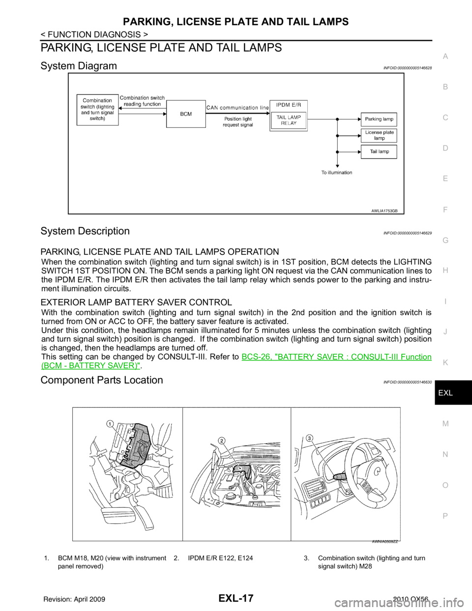
PARKING, LICENSE PLATE AND TAIL LAMPS
System DiagramINFOID:0000000005146628
System DescriptionINFOID:0000000005146629
PARKING, LICENSE PLATE AND TAIL LAMPS OPERATION
When the combination switch (lighting and turn signal s witch) is in 1ST position, BCM detects the LIGHTING
SWITCH 1ST POSITION ON. The BCM sends a parking light ON request via the CAN communication lines to
the IPDM E/R. The IPDM E/R then ac tivates the tail lamp relay which sends power to the parking and instru-
ment illumination circuits.
EXTERIOR LAMP BATTERY SAVER CONTROL
With the combination switch (lighting and turn signal switch) in the 2nd position and the ignition switch is
turned from ON or ACC to OFF, the battery saver feature is activated.
Under this condition, the headlamps remain illuminated fo r 5 minutes unless the combination switch (lighting
and turn signal switch) position is changed. If the combi nation switch (lighting and turn signal switch) position
is changed, then the headlamps are turned off.
This setting can be changed by CONSULT-III. Refer to BCS-26, "
BATTERY SAVER : CONSULT-III Function
(BCM - BATTERY SAVER)".
Component Parts LocationINFOID:0000000005146630
AWLIA1753GB
1. BCM M18, M20 (view with instrument
panel removed) 2. IPDM E/R E122, E124 3. Combination switch (lighting and turn
signal switch) M28
AWNIA0509ZZ
Revision: April 20092010 QX56
Page 1995 of 4210

DIAGNOSIS SYSTEM (BCM)EXL-19
< FUNCTION DIAGNOSIS >
C
DE
F
G H
I
J
K
M A
B
EXL
N
O P
DIAGNOSIS SYSTEM (BCM)
HEADLAMP
HEADLAMP : CONSULT-III Func tion (BCM - HEAD LAMP)INFOID:0000000005369883
WORK SUPPORT
*: Initial setting
DATA MONITOR
ACTIVE TEST
Work Item Setting item Setting
BATTERY SAVER SET ON* With the exterior lamp battery saver function
OFF Without the exterior lamp battery saver function
CUSTOM A/LIGHT SET-
TING MODE1* Normal
MODE2 More sensitive setting than normal setting (Turns ON earlier than normal operation.)
MODE3 More sensitive setting than MODE 2 (Turns ON earlier than MODE 2.)
MODE4 Less sensitive setting than normal setting (Turns ON later than normal operation.)
ILL DELAY SET MODE1* 45 sec.
Sets delay timer function timer operation time
(All doors closed)
MODE2
Without the func-
tion
MODE3 30 sec.
MODE4 60 sec.
MODE5 90 sec.
MODE6 120 sec.
MODE7 150 sec.
MODE8 180 sec.
Monitor Item [Unit] Description
IGN ON SW [ON/OFF] Ignition switch (ON) status judged from IGN signal (ignition power supply)
ACC ON SW [ON/OFF] Ignition switch (ACC) status judged from ACC signal (accessory power supply)
HI BEAM SW [ON/OFF]
Each switch status that BCM judges from the combination switch reading function
HEAD LAMP SW 1 [ON/OFF]
HEAD LAMP SW 2 [ON/OFF]
LIGHT SW 1ST [ON/OFF]
AUTO LIGHT SW [ON/OFF]
PASSING SW [ON/OFF]
FR FOG SW [ON/OFF]
TURN SIGNAL R [ON/OFF]
TURN SIGNAL L [ON/OFF]
DOOR SW-DR [ON/OFF]
The switch status input from front door switch LH
DOOR SW-AS [ON/OFF] The switch status input from front door switch RH
DOOR SW-RR [ON/OFF] The switch status input from rear door switch RH
DOOR SW-RL [ON/OFF] The switch status input from rear door switch LH
BACK DOOR SW [ON/OFF] The switch status input from back door switch
CARGO LAMP SW [ON/OFF] Cargo lamp status that BCM judges from the vehicle condition
OPTICAL SENSOR [ON/OFF] The value of exterior brightness voltage input from the optical sensor
Revision: April 20092010 QX56
Page 1996 of 4210

EXL-20
< FUNCTION DIAGNOSIS >
DIAGNOSIS SYSTEM (BCM)
FLASHER
FLASHER : CONSULT-III Function (BCM - FLASHER)INFOID:0000000005369884
DATA MONITOR
ACTIVE TEST
COMB SW
COMB SW : CONSULT-III Function (BCM - COMB SW)INFOID:0000000005369885
DATA MONITOR
Test ItemOperation Description
TA I L L A M P ON
Transmits the position light reques
t signal to IPDM E/R with CAN com-
munication to turn the tail lamp ON.
OFF Stops the tail lamp request signal transmission.
HEAD LAMP HI
Transmits the high beam request signal with CAN communication to turn
the headlamp (HI).
LO Transmits the low beam request signal with CAN communication to turn
the headlamp (LO).
OFF Stops the high & low beam request signal transmission.
FR FOG LAMP ON
Transmits the front fog lights request signal to IPDM E/R with CAN com-
munication to turn the front fog lamp ON.
OFF Stops the front fog lights request signal transmission.
CARGO LAMP ON
Transmits the cargo lamp request signal with CAN communication to
turn the lamp ON.
OFF Stops the cargo lamp request signal transmission.
CORNERING LAMP LH
Transmits the LH cornering lamp request signal with CAN communica-
tion to turn the lamp ON.
RH Transmits the RH cornering lamp request signal with CAN communica-
tion to turn the lamp ON.
OFF Stops the day time running light request signal transmission.
Monitor Item [Unit] Description
IGN ON SW [ON/OFF] Ignition switch (ON) status judged from IGN signal (ignition power supply)
HAZARD SW [ON/OFF] The switch status input from the hazard switch
TURN SIGNAL R [ON/OFF] Each switch condition that BCM judges from the combination switch reading function
TURN SIGNAL L [ON/OFF]
BRAKE SW [ON/OFF] The switch status input from the brake switch
Test ItemOperation Description
FLASHER RH Outputs the voltage to turn the right side turn signal lamps ON.
LH Outputs the voltage to turn the left side turn signal lamps ON.
OFF Stops the voltage to turn the turn signal lamps OFF.
Revision: April 20092010 QX56
Page 1998 of 4210

EXL-22
< FUNCTION DIAGNOSIS >
DIAGNOSIS SYSTEM (IPDM E/R)
DIAGNOSIS SYSTEM (IPDM E/R)
Diagnosis DescriptionINFOID:0000000005369886
AUTO ACTIVE TEST
Description
In auto active test mode, the IPDM E/R sends a drive signal to the follo wing systems to check their operation.
• Oil pressure low/coolant pressure high warning indicator
• Oil pressure gauge
• Rear window defogger
• Front wipers
• Tail, license and parking lamps
• Front fog lamps
• Headlamps (Hi, Lo)
• A/C compressor (magnetic clutch)
• Cooling fan
Operation Procedure
1. Close the hood and front door RH, and lift the wiper a rms from the windshield (to prevent windshield dam-
age due to wiper operation).
NOTE:
When auto active test is performed with hood opened, sprinkle water on windshield before hand.
2. Turn ignition switch OFF.
3. Turn the ignition switch ON and, within 20 seconds, press the front door switch LH 10 times. Then turn the ignition switch OFF.
4. Turn the ignition switch ON within 10 seconds. Af ter that the horn sounds once and the auto active test
starts.
5. After a series of the following operations is repeated 3 times, auto active test is completed.
NOTE:
When auto active test mode has to be cancelled halfway through test, turn ignition switch OFF.
CAUTION:
• If auto active test mode cannot be actuated, check door switch system. Refer to DLK-71, "
Descrip-
tion".
• Do not start the engine.
Inspection in Auto Active Test Mode
When auto active test mode is actuated, the following 7 steps are repeated 3 times.
Operation
sequence Inspection Location
Operation
1 Rear window defogger 10 seconds
2 Front wipers LO for 5 seconds → HI for 5 seconds
WKIA4655E
Revision: April 20092010 QX56
Page 2001 of 4210
![INFINITI QX56 2010 Factory Service Manual DIAGNOSIS SYSTEM (IPDM E/R)EXL-25
< FUNCTION DIAGNOSIS >
C
DE
F
G H
I
J
K
M A
B
EXL
N
O P
ACTIVE TEST
Te s t i t e m
TAIL&CLR REQ
[OFF/ON] ×Displays the status of the position light request signal r INFINITI QX56 2010 Factory Service Manual DIAGNOSIS SYSTEM (IPDM E/R)EXL-25
< FUNCTION DIAGNOSIS >
C
DE
F
G H
I
J
K
M A
B
EXL
N
O P
ACTIVE TEST
Te s t i t e m
TAIL&CLR REQ
[OFF/ON] ×Displays the status of the position light request signal r](/manual-img/42/57032/w960_57032-2000.png)
DIAGNOSIS SYSTEM (IPDM E/R)EXL-25
< FUNCTION DIAGNOSIS >
C
DE
F
G H
I
J
K
M A
B
EXL
N
O P
ACTIVE TEST
Te s t i t e m
TAIL&CLR REQ
[OFF/ON] ×Displays the status of the position light request signal received from BCM via CAN
communication.
HL LO REQ
[OFF/ON] ×
Displays the status of the low beam request signal received from BCM via CAN
communication.
HL HI REQ
[OFF/ON] ×Displays the status of the high beam request signal received from BCM via CAN
communication.
FR FOG REQ
[OFF/ON] ×Displays the status of the front fog lamp request signal received from BCM via
CAN communication.
FR WIP REQ
[STOP/1LOW/LOW/HI] ×
Displays the status of the front wiper request signal received from BCM via CAN
communication.
WIP AUTO STOP
[STOP P/ACT P] ×
Displays the status of the front wiper auto stop signal judged by IPDM E/R.
WIP PROT
[OFF/Block] ×
Displays the status of the front wiper fail-safe operation judged by IPDM E/R.
ST RLY REQ
[OFF/ON] Displays the status of the starter request signal received from ECM via CAN com-
munication.
IGN RLY
[OFF/ON] ×
Displays the status of the ignition relay judged by IPDM E/R.
RR DEF REQ
[OFF/ON] ×Displays the status of the rear defogger request signal received from AV control
unit via CAN communication.
OIL P SW
[OPEN/CLOSE] Displays the status of the oil pressure switch judged by IPDM E/R.
DTRL REQ
[OFF] Displays the status of the daytime light request signal received from BCM via CAN
communication.
HOOD SW
[OPEN/CLOSE] Displays the status of the hood switch judged by IPDM E/R.
THFT HRN REQ
[OFF/ON] Displays the status of the theft warning horn request signal received from BCM
via CAN communication.
HORN CHIRP
[OFF/ON] Displays the status of the horn reminder signal received from BCM via CAN com-
munication.
Monitor Item
[Unit] MAIN SIG-
NALS Description
Test item
Operation Description
REAR DEFOGGER OFF
OFF
ON Operates rear window defogger relay.
FRONT WIPER OFF
OFF
LO Operates the front wiper relay.
HI Operates the front wiper relay and front wiper high relay.
MOTOR FAN 1O
FF
2O FF
3 Operates the cooling fan relay.
4 Operates the cooling fan relay.
Revision: April 20092010 QX56