Page 2777 of 4210
MWI
METER SYSTEMMWI-15
< FUNCTION DIAGNOSIS >
C
DE
F
G H
I
J
K L
M B A
O P
VOLTAGE GAUGE : System DiagramINFOID:0000000005146050
VOLTAGE GAUGE : System DescriptionINFOID:0000000005146051
The voltage gauge indicates the battery/charging system voltage.
The voltage gauge is regulated by the unified meter control unit.
VOLTAGE GAUGE : Component Parts LocationINFOID:0000000005146052
AWNIA0106GB
1. IPDM E/R E122, E124 2. Combination meter M23, M24 3. Fuel level sensor unit and fuel pump
C5 (view with inspection hole cover re-
moved)
4. ECM E16 (view with battery removed) 5. ABS actuator and electric unit (control unit) E1256. Oil pressure switch F4
A: Oil pan (upper)
7. A/T assembly F9 8. BCM M18, M19 (view with instrument
lower panel LH removed)
AWNIA0201ZZ
Revision: April 20092010 QX56
Page 2779 of 4210
MWI
METER SYSTEMMWI-17
< FUNCTION DIAGNOSIS >
C
DE
F
G H
I
J
K L
M B A
O PODO/TRIP METER : Component DescriptionINFOID:0000000005146057
SHIFT POSITION INDICATOR
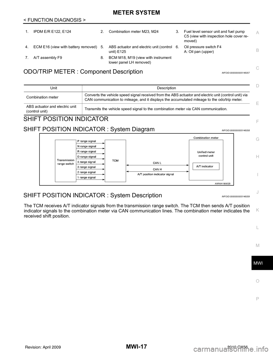
SHIFT POSITION INDICATOR : System DiagramINFOID:0000000005146058
SHIFT POSITION INDICATOR : System DescriptionINFOID:0000000005146059
The TCM receives A/T indicator signals from the tr ansmission range switch. The TCM then sends A/T position
indicator signals to the combination meter via CAN co mmunication lines. The combination meter indicates the
received shift position.
1. IPDM E/R E122, E124 2. Combination meter M23, M24 3. Fuel level sensor unit and fuel pump
C5 (view with inspection hole cover re-
moved)
4. ECM E16 (view with battery removed) 5. ABS actuator and electric unit (control unit) E1256. Oil pressure switch F4
A: Oil pan (upper)
7. A/T assembly F9 8. BCM M18, M19 (view with instrument
lower panel LH removed)
Unit Description
Combination meter Converts the vehicle speed signal
received from the ABS actuator and electric unit (control unit) via
CAN communication to mileage, and it displays the accumulated mileage to the odo/trip meter.
ABS actuator and electric unit
(control unit) Transmits the vehicle speed signal to the combination meter via CAN communication.
AWNIA1906GB
Revision: April 20092010 QX56
Page 2780 of 4210
MWI-18
< FUNCTION DIAGNOSIS >
METER SYSTEM
SHIFT POSITION INDICATOR : Component Parts Location
INFOID:0000000005146060
SHIFT POSITION INDICATOR : Component DescriptionINFOID:0000000005146061
WARNING LAMPS/INDICATOR LAMPS
WARNING LAMPS/INDICATOR LAMPS : System DiagramINFOID:0000000005146062
1. IPDM E/R E122, E124 2. Combination meter M23, M24 3. Fuel level sensor unit and fuel pump
C5 (view with inspection hole cover re-
moved)
4. ECM E16 (view with battery removed) 5. ABS actuator and electric unit (control
unit) E125 6. Oil pressure switch F4
A: Oil pan (upper)
7. A/T assembly F9 8. BCM M18, M19 (view with instrument
lower panel LH removed)
AWNIA0201ZZ
Unit Description
Combination meter Displays the shift position on the information display using shift position signal received from TCM.
TCM Transmits the shift position signal to the combination meter via CAN communication.
JSNIA0449GB
Revision: April 20092010 QX56
Page 2781 of 4210
MWI
METER SYSTEMMWI-19
< FUNCTION DIAGNOSIS >
C
DE
F
G H
I
J
K L
M B A
O P
WARNING LAMPS/INDICATOR LAMPS : System DescriptionINFOID:0000000005146063
OIL PRESSURE WARNING LAMP
• IPDM E/R reads the ON/OFF signals from the oil pressure switch and transmits the oil pressure switch sig-
nal to the combination meter via BCM with the CAN communication line.
• The combination meter turns the oil pressure warning lamp ON/OFF according to the oil pressure switch sig- nal received via CAN communication.
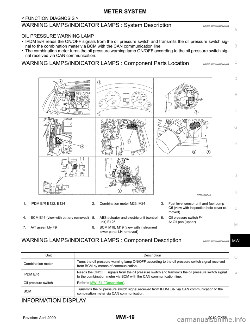
WARNING LAMPS/INDICATOR LAMPS : Component Parts LocationINFOID:0000000005146064
WARNING LAMPS/INDICATOR LAMPS : Component DescriptionINFOID:0000000005146065
INFORMATION DISPLAY
1. IPDM E/R E122, E124 2. Combination meter M23, M24 3. Fuel level sensor unit and fuel pump
C5 (view with inspection hole cover re-
moved)
4. ECM E16 (view with battery removed) 5. ABS actuator and electric unit (control unit) E1256. Oil pressure switch F4
A: Oil pan (upper)
7. A/T assembly F9 8. BCM M18, M19 (view with instrument
lower panel LH removed)
AWNIA0201ZZ
Unit Description
Combination meter Turns the oil pressure warning lamp ON/OFF according to the oil pressure switch signal received
from BCM by means of communication.
IPDM E/R Reads the ON/OFF signals from the oil pressure switch and transmits the oil pressure switch signal
to the combination meter via BCM with the CAN communication line.
Oil pressure switch Refer to MWI-34, "
Description".
BCM Transmits the oil pressure switch signal received from IPDM E/R via CAN communication to the
combination meter via CAN communication.
Revision: April 20092010 QX56
Page 2783 of 4210
MWI
METER SYSTEMMWI-21
< FUNCTION DIAGNOSIS >
C
DE
F
G H
I
J
K L
M B A
O P
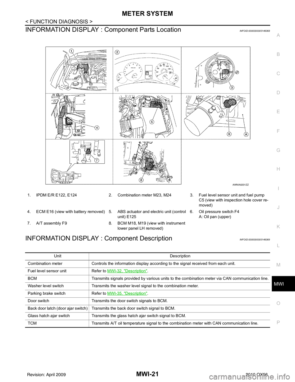
INFORMATION DISPLAY : Co mponent Parts LocationINFOID:0000000005146068
INFORMATION DISPLAY : Component DescriptionINFOID:0000000005146069
1. IPDM E/R E122, E124 2. Combination meter M23, M24 3. Fuel level sensor unit and fuel pump
C5 (view with inspection hole cover re-
moved)
4. ECM E16 (view with battery removed) 5. ABS actuator and electric unit (control unit) E1256. Oil pressure switch F4
A: Oil pan (upper)
7. A/T assembly F9 8. BCM M18, M19 (view with instrument
lower panel LH removed)
AWNIA0201ZZ
Unit Description
Combination meter Controls the information display according to the signal received from each unit.
Fuel level sensor unit Refer to MWI-32, "
Description".
BCM Transmits signals provided by various units to the combination meter via CAN communication line.
Washer level switch Transmits the washer level signal to the combination meter.
Parking brake switch Refer to MWI-35, "
Description".
Door switch Transmits the door switch signals to BCM.
Back door latch (door ajar switch) Transmits the back door switch signal to BCM.
Glass hatch ajar switch Transmits the glass hatch ajar switch signal to BCM.
TCM Transmits A/T oil temperature signal to the combination meter with CAN communication line.
Revision: April 20092010 QX56
Page 2868 of 4210
PARKING BRAKE SYSTEMPB-5
< ON-VEHICLE MAINTENANCE >
C
DE
G H
I
J
K L
M A
B
PB
N
O P
ON-VEHICLE MAINTENANCE
PARKING BRAKE SYSTEM
On-Vehicle ServiceINFOID:0000000005147932
PEDAL STROKE
• When parking brake pedal is operated with the specified forc e, make sure the stroke is within the specified
number of notches. Check by listening and counting the ratchet clicks.
INSPECTION
• Make sure the components are attached pr operly, checking for looseness or backlash.
• Check parking brake pedal assembly for bends, damage and cracks, and replace if necessary.
• Check cable for wear and damage, and replace if necessary.
• Check parking brake warning lamp switch for malfunction, and replace if necessary. Refer to BCS-38, "
Diag-
nosis Procedure".
ADJUSTMENT
1. Remove the lower instrument panel LH. Refer to IP-14, "Exploded View".
2. Partially engage parking brake pedal to access adjusting nut.
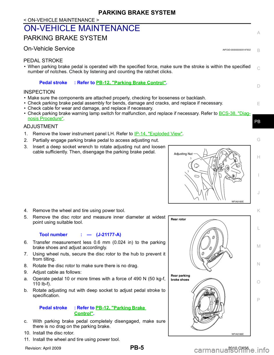
3. Insert a deep socket wrench to rotate adjusting nut and loosen cable sufficiently. Then, disengage the parking brake pedal.
4. Remove the wheel and tire using power tool.
5. Remove the disc rotor and measure inner diameter at widest point using suitable tool.
6. Transfer measurement less 0.6 mm (0.024 in) to the parking brake shoes and adjust accordingly.
7. Using wheel nuts, secure the disc rotor to the hub to prevent it from tilting.
8. Rotate the disc rotor to make sure there is no drag.
9. Adjust cable as follows:
a. Operate pedal 10 or more times with a force of 490 N (50 kg-f, 110 lb-f).
b. Rotate adjusting nut with deep socket to adjust pedal stroke to specification.
c. With parking brake pedal completely disengaged, make sure there is no drag on the parking brake.
10. Install the disc rotor.
11. Install the wheel and tire using power tool. Pedal stroke : Refer to
PB-12, "
Parking Brake Control".
WFIA0165E
Tool number : — (J-21177-A)
Pedal stroke : Refer to PB-12, "
Parking Brake
Control".
WFIA0166E
Revision: April 20092010 QX56
Page 2869 of 4210
PB-6
< ON-VEHICLE MAINTENANCE >
PARKING BRAKE SYSTEM
12. Install the lower instrument panel LH. Refer to IP-14, "Exploded View".
Revision: April 20092010 QX56
Page 2870 of 4210
PARKING BRAKE CONTROLPB-7
< ON-VEHICLE REPAIR >
C
DE
G H
I
J
K L
M A
B
PB
N
O P
ON-VEHICLE REPAIR
PARKING BRAKE CONTROL
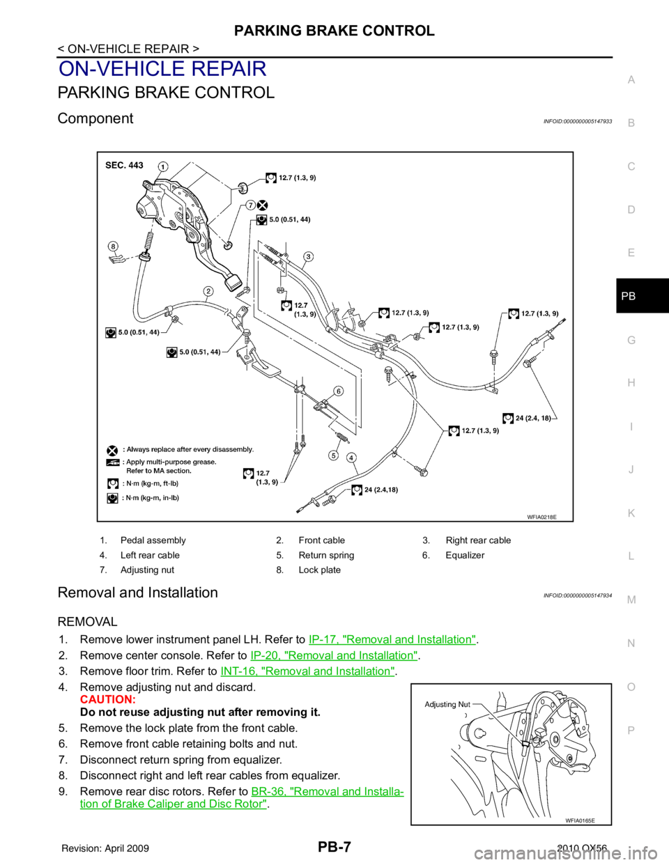
ComponentINFOID:0000000005147933
Removal and InstallationINFOID:0000000005147934
REMOVAL
1. Remove lower instrument panel LH. Refer to IP-17, "Removal and Installation".
2. Remove center console. Refer to IP-20, "
Removal and Installation".
3. Remove floor trim. Refer to INT-16, "
Removal and Installation".
4. Remove adjusting nut and discard. CAUTION:
Do not reuse adjusting nut after removing it.
5. Remove the lock plate from the front cable.
6. Remove front cable retaining bolts and nut.
7. Disconnect return spring from equalizer.
8. Disconnect right and left rear cables from equalizer.
9. Remove rear disc rotors. Refer to BR-36, "
Removal and Installa-
tion of Brake Caliper and Disc Rotor".
1. Pedal assembly 2. Front cable3. Right rear cable
4. Left rear cable 5. Return spring6. Equalizer
7. Adjusting nut 8. Lock plate
WFIA0218E
WFIA0165E
Revision: April 20092010 QX56