Page 3726 of 4210
ON BOARD DIAGNOSTIC (OBD) SYSTEMTM-31
< FUNCTION DIAGNOSIS >
CEF
G H
I
J
K L
M A
B
TM
N
O P
longer stored. Remember, only one set of freeze frame data can be stored in the ECM. The ECM has the fol-
lowing priorities to update the data.
Both 1st trip freeze frame data and freeze frame data (along with the DTC) are cleared when the ECM mem-
ory is erased.
HOW TO ERASE DTC
The diagnostic trouble code can be erased by CONSULT- III, GST or ECM DIAGNOSTIC TEST MODE as
described following.
• If the battery cable is disconnected, the diagnostic trouble code will be lost within 24 hours.
• When you erase the DTC, using CONSULT-III or GS T is easier and quicker than switching the mode
selector on the ECM.
The following emission-related diagnostic information is cleared from the ECM memory when erasing DTC
related to OBD-II. For details, refer to EC-42, "
Emission-related Diagnostic Information".
• Diagnostic trouble codes (DTC)
• 1st trip diagnostic trouble codes (1st trip DTC)
• Freeze frame data
• 1st trip freeze frame data
• System readiness test (SRT) codes
• Test values
HOW TO ERASE DTC (WITH CONSULT-III)
1. The emission related diagnostic information in the TCM and ECM can be er\
ased by selectioning "ALL
ERASE" in the "Description" of "F INAL CHECK" mode with CONSULT-III.
HOW TO ERASE DTC (WITH GST)
1. If the ignition switch stays “ON” after repair work, be sure to turn ignition switch “OFF” once. Wait at least
10 seconds and then turn it “ON” (engine stopped) again.
2. Select Mode 4 with the Generic Scan Tool (GST). For details refer to EC-72, "
Generic Scan Tool (GST)
Function".
HOW TO ERASE DTC (NO TOOLS)
1. Disconnect battery for 24 hours.
2. Reconnect battery.
Malfunction Indicator Lamp (MIL)INFOID:0000000005148525
DESCRIPTION
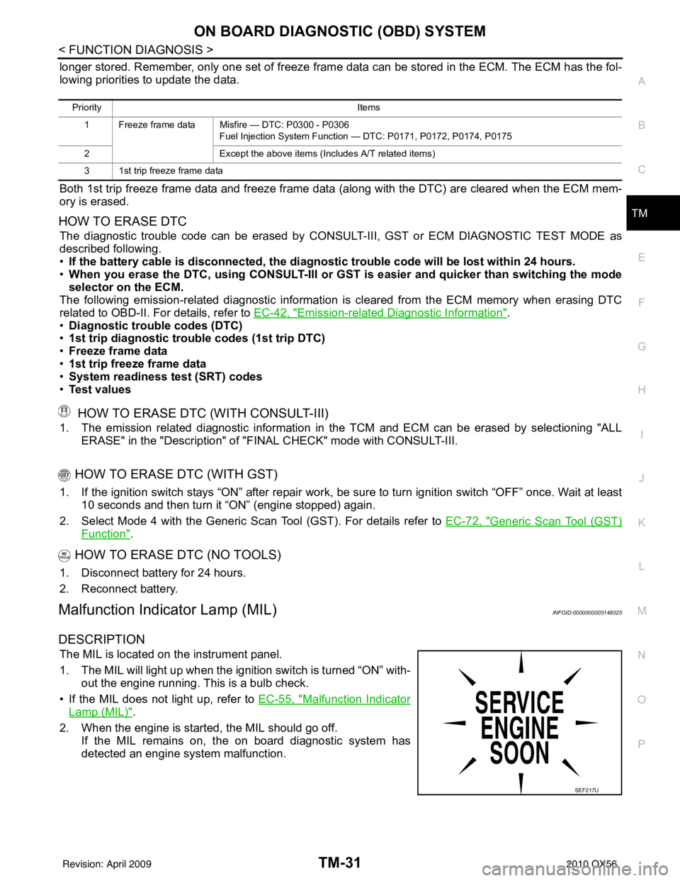
The MIL is located on the instrument panel.
1. The MIL will light up when the ignition switch is turned “ON” with-
out the engine running. This is a bulb check.
• If the MIL does not light up, refer to EC-55, "
Malfunction Indicator
Lamp (MIL)".
2. When the engine is start ed, the MIL should go off.
If the MIL remains on, the on board diagnostic system has
detected an engine system malfunction.
Priority Items
1 Freeze frame data Misfire — DTC: P0300 - P0306 Fuel Injection System Function — DTC: P0171, P0172, P0174, P0175
2 Except the above items (Includes A/T related items)
3 1st trip freeze frame data
SEF217U
Revision: April 20092010 QX56
Page 3968 of 4210
VTL-6
< ON-VEHICLE MAINTENANCE >
IN-CABIN MICROFILTER
ON-VEHICLE MAINTENANCE
IN-CABIN MICROFILTER
Removal and InstallationINFOID:0000000005147604
REPLACEMENT PROCEDURE
1. Remove the glove box assembly from the instrument panel. Refer to IP-17, "Removal and Installation".
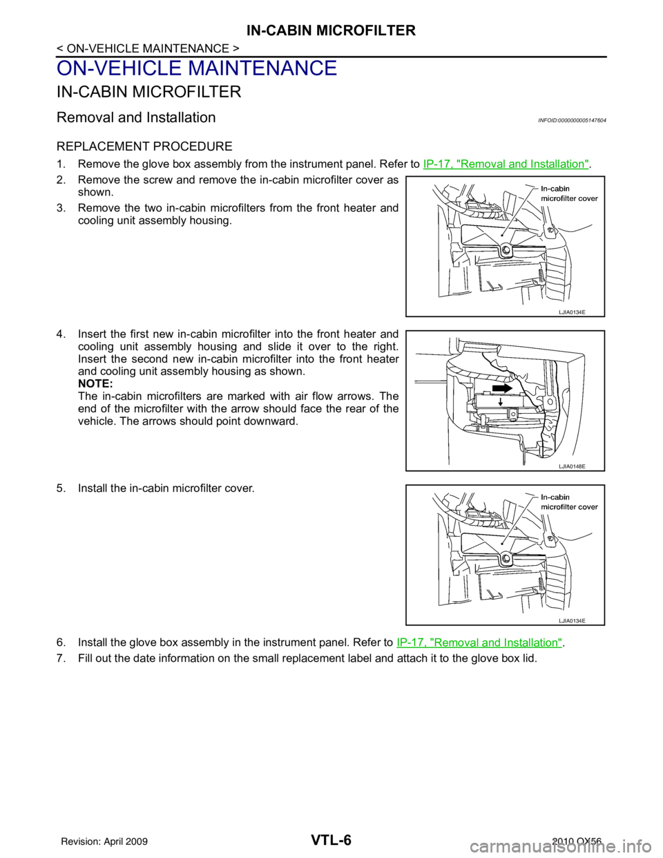
2. Remove the screw and remove the in-cabin microfilter cover as shown.
3. Remove the two in-cabin microf ilters from the front heater and
cooling unit assembly housing.
4. Insert the first new in-cabin micr ofilter into the front heater and
cooling unit assembly housing and slide it over to the right.
Insert the second new in-cabin mi crofilter into the front heater
and cooling unit assembly housing as shown.
NOTE:
The in-cabin microfilters are marked with air flow arrows. The
end of the microfilter with the arro w should face the rear of the
vehicle. The arrows should point downward.
5. Install the in-cabin microfilter cover.
6. Install the glove box assembly in the instrument panel. Refer to IP-17, "
Removal and Installation".
7. Fill out the date information on the small replac ement label and attach it to the glove box lid.
LJIA0134E
LJIA0148E
LJIA0134E
Revision: April 20092010 QX56
Page 3969 of 4210
CONTROL UNITVTL-7
< ON-VEHICLE REPAIR >
C
DE
F
G H
J
K L
M A
B
VTL
N
O P
ON-VEHICLE REPAIR
CONTROL UNIT
Removal and InstallationINFOID:0000000005147605
A/C and AV SWITCH ASSEMBLY
Removal and Installation
The front A/C switch is integrated into the A/C and AV swit ch assembly in cluster lid C in the instrument panel.
Refer to AV-169, "
Removal and Installation".
A/C AUTO AMP.
Removal
1. Remove the display unit. Refer to AV-171, "Removal and Installation".
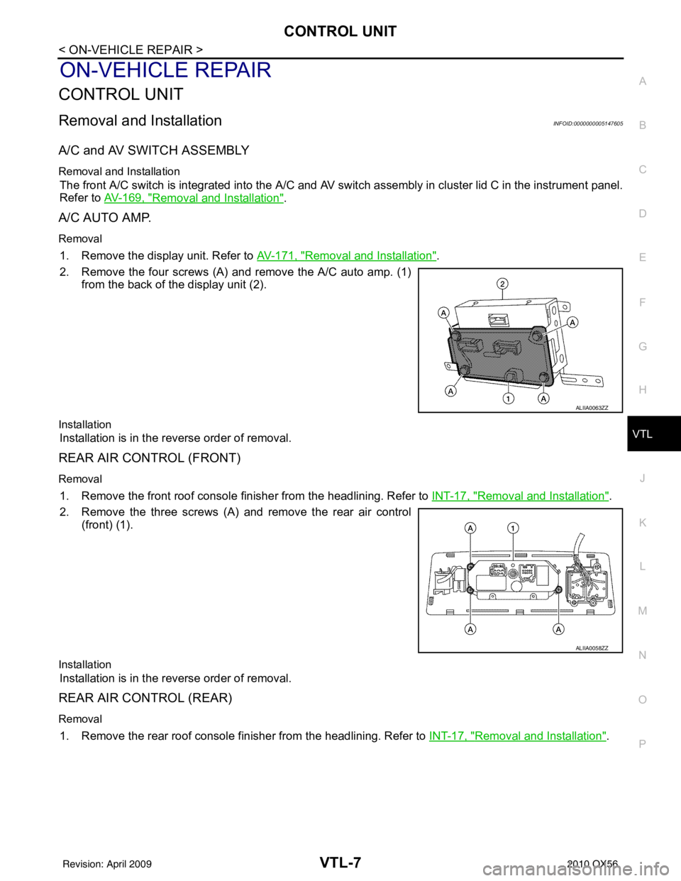
2. Remove the four screws (A) and remove the A/C auto amp. (1) from the back of the display unit (2).
Installation
Installation is in the reverse order of removal.
REAR AIR CONTROL (FRONT)
Removal
1. Remove the front roof console finisher from the headlining. Refer to INT-17, "Removal and Installation".
2. Remove the three screws (A) and remove the rear air control (front) (1).
Installation
Installation is in the reverse order of removal.
REAR AIR CONTROL (REAR)
Removal
1. Remove the rear roof console finisher from the headlining. Refer to INT-17, "Removal and Installation".
ALIIA0063ZZ
ALIIA0058ZZ
Revision: April 20092010 QX56
Page 3971 of 4210
IN-VEHICLE SENSORVTL-9
< ON-VEHICLE REPAIR >
C
DE
F
G H
J
K L
M A
B
VTL
N
O P
IN-VEHICLE SENSOR
Removal and InstallationINFOID:0000000005147606
REMOVAL
1. Remove the lower instrument panel LH. Refer to IP-11, "Exploded View".
2. Remove the two screws (A) and remove the in-vehicle sensor (1).
INSTALLATION
Installation is in the reverse order of removal.
ALIIA0060ZZ
Revision: April 20092010 QX56
Page 3972 of 4210
VTL-10
< ON-VEHICLE REPAIR >
OPTICAL SENSOR
OPTICAL SENSOR
Removal and InstallationINFOID:0000000005147607
REMOVAL
1. Remove the defroster grille from the instrument panel. Refer to VTL-36, "Removal and Installation".
2. Disconnect the optical sensor connector (2).
3. Twist the optical sensor (1) counter clockwise to remove it from the defroster grille.
INSTALLATION
Installation is in the reverse order of removal.
ALIIA0061ZZ
Revision: April 20092010 QX56
Page 3973 of 4210
INTAKE SENSORVTL-11
< ON-VEHICLE REPAIR >
C
DE
F
G H
J
K L
M A
B
VTL
N
O P
INTAKE SENSOR
Removal and InstallationINFOID:0000000005147608
REMOVAL
1. Remove the instrument lower panel RH and glove box. Refer to IP-17, "Removal and Installation".
2. Disconnect the intake sensor electrical connector. NOTE:
The intake sensor is located on the top of the front heater and
cooling unit assembly next to the A/C evaporator cover.
3. Pull up on the intake sensor to remove the intake sensor from the front heater and cooling unit assembly.
INSTALLATION
Installation is in the reverse order of removal.
LJIA0133E
Revision: April 20092010 QX56
Page 3980 of 4210
VTL-18
< ON-VEHICLE REPAIR >
HEATER & COOLING UNIT ASSEMBLY
1. Move the two front seats to the rear most position on the seat track.
2. Disconnect the battery negative terminal and battery positive terminal.
3. Discharge the refrigerant from the A/C system. Refer to HA-20, "
HFC-134a (R-134a) Service Procedure".
4. Drain the coolant from the engine cooling system. Refer to CO-11, "
Changing Engine Coolant".
5. Disconnect the front heater hoses from the front heater core.
6. Disconnect the high/low pressure pipes from the front expansion valve.
7. Remove the instrument panel and console panel. Refer to IP-12, "
Removal and Installation".
8. Disconnect the instrument panel wire harness at the RH and LH in-line connector brackets, and the fuse block (J/B) electrical connectors. Refer to PG-9, "
Wiring Diagram — Battery Power Supply —".
9. Disconnect the steering member from each side of the vehicle body.
10. Remove the front heater and cooling unit assembly with it attached to the steering member, from the vehi-
cle.
CAUTION:
Use care not to damage the seats and interior tr im panels when removing the front heater and
cooling unit assembly with it at tached to the steering member.
11. Remove the front heater and cooling unit assembly from the steering member.
Installation
Installation is in the reverse order of removal.
CAUTION:
• Replace the O-ring of the low-pressure pipe and high-pressure pipe with a new one, and apply com-
pressor oil to it when installing it.
• After charging the refrigerant, check for leaks.
NOTE:
• Fill the engine cooling system with the specified coolant mixture. Refer to CO-11, "
Changing Engine Cool-
ant".
• Recharge the A/C system. Refer to HA-20, "
HFC-134a (R-134a) Service Procedure".
REAR HEATER AND COOLING UNIT ASSEMBLY
Removal
1. Discharge the refrigerant from the A/C system. Refer to HA-20, "HFC-134a (R-134a) Service Procedure".
2. Drain the coolant from the engine cooling system. Refer to CO-11, "
Changing Engine Coolant".
3. Remove the luggage side finisher lower and upper RH. Refer to INT-19, "
Removal and Installation".
4. Disconnect the rear heater core hoses from the rear heater core.
5. Disconnect the rear A/C pipes from the rear expansion valve.
6. Disconnect the following electrical connectors: • Rear blower motor
• Rear variable blower control
• Rear air mix door motor
• Rear mode door motor
7. Disconnect the ducts and drain tube from the rear heater and cooling unit assembly.
8. Remove the rear heater and cooling unit assembly.
Installation
Installation is in the reverse order of removal.
CAUTION:
• Replace the O-ring of the low-pressure pipe and high-pressure pipe with a new one, and apply com-
pressor oil to it when installing it.
• After charging the refrigerant, check for leaks.
NOTE:
• Fill the engine cooling system with the specified coolant mixture. Refer to CO-11, "
Changing Engine Cool-
ant".
• Recharge the A/C system. Refer to HA-20, "
HFC-134a (R-134a) Service Procedure".
Revision: April 20092010 QX56
Page 3991 of 4210
MODE DOOR MOTORVTL-29
< ON-VEHICLE REPAIR >
C
DE
F
G H
J
K L
M A
B
VTL
N
O P
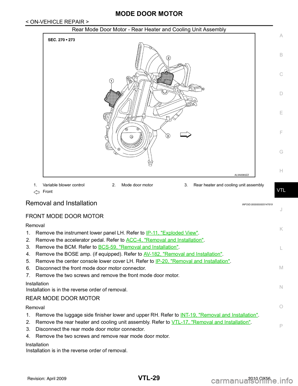
Rear Mode Door Motor - Rear Heater and Cooling Unit Assembly
Removal and InstallationINFOID:0000000005147619
FRONT MODE DOOR MOTOR
Removal
1. Remove the instrument lower panel LH. Refer to IP-11, "Exploded View".
2. Remove the accelerator pedal. Refer to ACC-4, "
Removal and Installation".
3. Remove the BCM. Refer to BCS-59, "
Removal and Installation".
4. Remove the BOSE amp. (if equipped). Refer to AV-182, "
Removal and Installation".
5. Remove the center console lower cover LH. Refer to IP-20, "
Removal and Installation".
6. Disconnect the front mode door motor connector.
7. Remove the two screws and remove the front mode door motor.
Installation
Installation is in the reverse order of removal.
REAR MODE DOOR MOTOR
Removal
1. Remove the luggage side finisher lower and upper RH. Refer to INT-19, "Removal and Installation".
2. Remove the rear heater and cooling unit assembly. Refer to VTL-17, "
Removal and Installation".
3. Disconnect the rear mode door motor connector.
4. Remove the two screws and remove rear mode door motor.
Installation
Installation is in the reverse order of removal.
ALIIA0065ZZ
1. Variable blower control 2. Mode door motor3. Rear heater and cooling unit assembly
Front
Revision: April 20092010 QX56