2010 INFINITI QX56 IP cluster
[x] Cancel search: IP clusterPage 366 of 4210
![INFINITI QX56 2010 Factory Service Manual AV
AV CONTROL UNITAV-169
< ON-VEHICLE REPAIR > [AUDIO SYSTEM]
C
D
E
F
G H
I
J
K L
M B A
O P
ON-VEHICLE REPAIR
AV CONTROL UNIT
Removal and InstallationINFOID:0000000005146356
CAUTION:
1. Cluster lid C](/manual-img/42/57032/w960_57032-365.png "INFINITI QX56 2010 Factory Service Manual AV
AV CONTROL UNITAV-169
< ON-VEHICLE REPAIR > [AUDIO SYSTEM]
C
D
E
F
G H
I
J
K L
M B A
O P
ON-VEHICLE REPAIR
AV CONTROL UNIT
Removal and InstallationINFOID:0000000005146356
CAUTION:
1. Cluster lid C")
AV
AV CONTROL UNITAV-169
< ON-VEHICLE REPAIR > [AUDIO SYSTEM]
C
D
E
F
G H
I
J
K L
M B A
O P
ON-VEHICLE REPAIR
AV CONTROL UNIT
Removal and InstallationINFOID:0000000005146356
CAUTION:
1. Cluster lid C 2. AV switch 3. AV control unit
4. AV control unit brackets 5. Tuner knob switch6. A/C and AV switch assembly
7. Volume knob switch 8. Volume knob9. Temp knobs RH and LH
10. Enter button 11. Tuner knob
ALNIA0201ZZ
Revision: April 20092010 QX56
Page 367 of 4210
![INFINITI QX56 2010 Factory Service Manual AV-170
< ON-VEHICLE REPAIR >[AUDIO SYSTEM]
AV CONTROL UNIT
Only remove and replace the A/C or AV switch
assembly knobs if damaged or missing. The knobs
must not be removed from the switches when remo](/manual-img/42/57032/w960_57032-366.png "INFINITI QX56 2010 Factory Service Manual AV-170
< ON-VEHICLE REPAIR >[AUDIO SYSTEM]
AV CONTROL UNIT
Only remove and replace the A/C or AV switch
assembly knobs if damaged or missing. The knobs
must not be removed from the switches when remo")
AV-170
< ON-VEHICLE REPAIR >[AUDIO SYSTEM]
AV CONTROL UNIT
Only remove and replace the A/C or AV switch
assembly knobs if damaged or missing. The knobs
must not be removed from the switches when remo ving and installing the A/C or AV switch assembly
to prevent damage to the switch assembly.
REMOVAL
1. Disconnect the battery negative terminal.
2. Remove the cluster lid C. Refer to IP-15, "
Removal and Installation".
3. Remove the AV control unit screws, using a power tool.
4. Remove the AV control unit.
5. Remove the A/C and AV switch assembly screws, then remove the A/C and AV switch assembles as nec- essary.
INSTALLATION
Installation is in the reverse order of removal.
Revision: April 20092010 QX56
Page 368 of 4210
![INFINITI QX56 2010 Factory Service Manual AV
DISPLAY UNITAV-171
< ON-VEHICLE REPAIR > [AUDIO SYSTEM]
C
D
E
F
G H
I
J
K L
M B A
O P
DISPLAY UNIT
Removal and InstallationINFOID:0000000005146357
REMOVAL
1. Remove cluster lid C. Refer to IP-15,](/manual-img/42/57032/w960_57032-367.png "INFINITI QX56 2010 Factory Service Manual AV
DISPLAY UNITAV-171
< ON-VEHICLE REPAIR > [AUDIO SYSTEM]
C
D
E
F
G H
I
J
K L
M B A
O P
DISPLAY UNIT
Removal and InstallationINFOID:0000000005146357
REMOVAL
1. Remove cluster lid C. Refer to IP-15,")
AV
DISPLAY UNITAV-171
< ON-VEHICLE REPAIR > [AUDIO SYSTEM]
C
D
E
F
G H
I
J
K L
M B A
O P
DISPLAY UNIT
Removal and InstallationINFOID:0000000005146357
REMOVAL
1. Remove cluster lid C. Refer to IP-15, "Removal and Installation".
2. Remove the display unit screws (A), pull out the display unit (1) from instrument panel, to disconnect the display unit connectors.
3. Remove the A/C auto amp. screws (A) and the A/C auto amp. (1).
• Display unit (2)
4. Remove the display unit bracket screws and the display unit brackets.
INSTALLATION
Installation is in the reverse order of removal.
ALNIA0272ZZ
ALIIA0063ZZ
Revision: April 20092010 QX56
Page 383 of 4210
![INFINITI QX56 2010 Factory Service Manual AV-186
< ON-VEHICLE REPAIR >[AUDIO SYSTEM]
GPS ANTENNA
GPS ANTENNA
Removal and InstallationINFOID:0000000005146372
REMOVAL
1. Remove the cluster lid C. Refer to
IP-12, "Removal and Installation".
2.](/manual-img/42/57032/w960_57032-382.png "INFINITI QX56 2010 Factory Service Manual AV-186
< ON-VEHICLE REPAIR >[AUDIO SYSTEM]
GPS ANTENNA
GPS ANTENNA
Removal and InstallationINFOID:0000000005146372
REMOVAL
1. Remove the cluster lid C. Refer to
IP-12, \"Removal and Installation\".
2.")
AV-186
< ON-VEHICLE REPAIR >[AUDIO SYSTEM]
GPS ANTENNA
GPS ANTENNA
Removal and InstallationINFOID:0000000005146372
REMOVAL
1. Remove the cluster lid C. Refer to
IP-12, "Removal and Installation".
2. Disconnect the center speaker.
3. Remove the defroster grille. Refer to IP-12, "
Removal and Installation".
4. Disconnect the GPS antenna connector.
5. Remove the GPS antenna.
INSTALLATION
Installation is in the reverse order of removal.
WKIA1509E
WKIA1508E
Revision: April 20092010 QX56
Page 1059 of 4210
![INFINITI QX56 2010 Factory Service Manual SQUEAK AND RATTLE TROUBLE DIAGNOSESDLK-225
< SYMPTOM DIAGNOSIS > [WITH INTELLIGENT KEY SYSTEM]
C
D
E
F
G H
I
J
L
M A
B
DLK
N
O P
Insulates where slight movement is present. Ideal for instrument panel](/manual-img/42/57032/w960_57032-1058.png "INFINITI QX56 2010 Factory Service Manual SQUEAK AND RATTLE TROUBLE DIAGNOSESDLK-225
< SYMPTOM DIAGNOSIS > [WITH INTELLIGENT KEY SYSTEM]
C
D
E
F
G H
I
J
L
M A
B
DLK
N
O P
Insulates where slight movement is present. Ideal for instrument panel")
SQUEAK AND RATTLE TROUBLE DIAGNOSESDLK-225
< SYMPTOM DIAGNOSIS > [WITH INTELLIGENT KEY SYSTEM]
C
D
E
F
G H
I
J
L
M A
B
DLK
N
O P
Insulates where slight movement is present. Ideal for instrument panel applications.
SILICONE GREASE
Used in place of UHMW tape that will be visible or not fit. Will only last a few months.
SILICONE SPRAY
Use when grease cannot be applied.
DUCT TAPE
Use to eliminate movement.
CONFIRM THE REPAIR
Confirm that the cause of a noise is repaired by test driving the vehicle. Operate the vehicle under the same
conditions as when the noise originally occurred. Refer to the notes on the Diagnostic Worksheet.
Inspection ProcedureINFOID:0000000005147044
Refer to Table of Contents for specific component removal and installation information.
INSTRUMENT PANEL
Most incidents are caused by contact and movement between:
1. The cluster lid A and instrument panel
2. Acrylic lens and combination meter housing
3. Instrument panel to front pillar garnish
4. Instrument panel to windshield
5. Instrument panel mounting pins
6. Wiring harnesses behind the combination meter
7. A/C defroster duct and duct joint
These incidents can usually be located by tapping or moving the components to duplicate the noise or by
pressing on the components while driving to stop the noi se. Most of these incidents can be repaired by apply-
ing felt cloth tape or silicon spray (in hard to reach areas). Urethane pads can be used to insulate wiring har-
ness.
CAUTION:
Do not use silicone spray to isolate a squeak or ra ttle. If you saturate the area with silicone, you will
not be able to recheck the repair.
CENTER CONSOLE
Components to pay attention to include:
1. Shifter assembly cover to finisher
2. A/C control unit and cluster lid C
3. Wiring harnesses behind audio and A/C control unit
The instrument panel repair and isolation pr ocedures also apply to the center console.
DOORS
Pay attention to the:
1. Finisher and inner panel making a slapping noise
2. Inside handle escutcheon to door finisher
3. Wiring harnesses tapping
4. Door striker out of alignment causing a popping noise on starts and stops
Tapping or moving the components or pressing on them while driving to duplicate the conditions can isolate
many of these incidents. You can usually insulate the ar eas with felt cloth tape or insulator foam blocks from
the Nissan Squeak and Rattle Kit (J-43980) to repair the noise.
TRUNK
Trunk noises are often caused by a loose jack or loose items put into the trunk by the owner.
In addition look for:
1. Trunk lid dampers out of adjustment
2. Trunk lid striker out of adjustment
3. The trunk lid torsion bars knocking together
4. A loose license plate or bracket
Revision: April 20092010 QX56
Page 2131 of 4210
HAZARD SWITCHEXL-155
< REMOVAL AND INSTALLATION >
C
DE
F
G H
I
J
K
M A
B
EXL
N
O P
HAZARD SWITCH
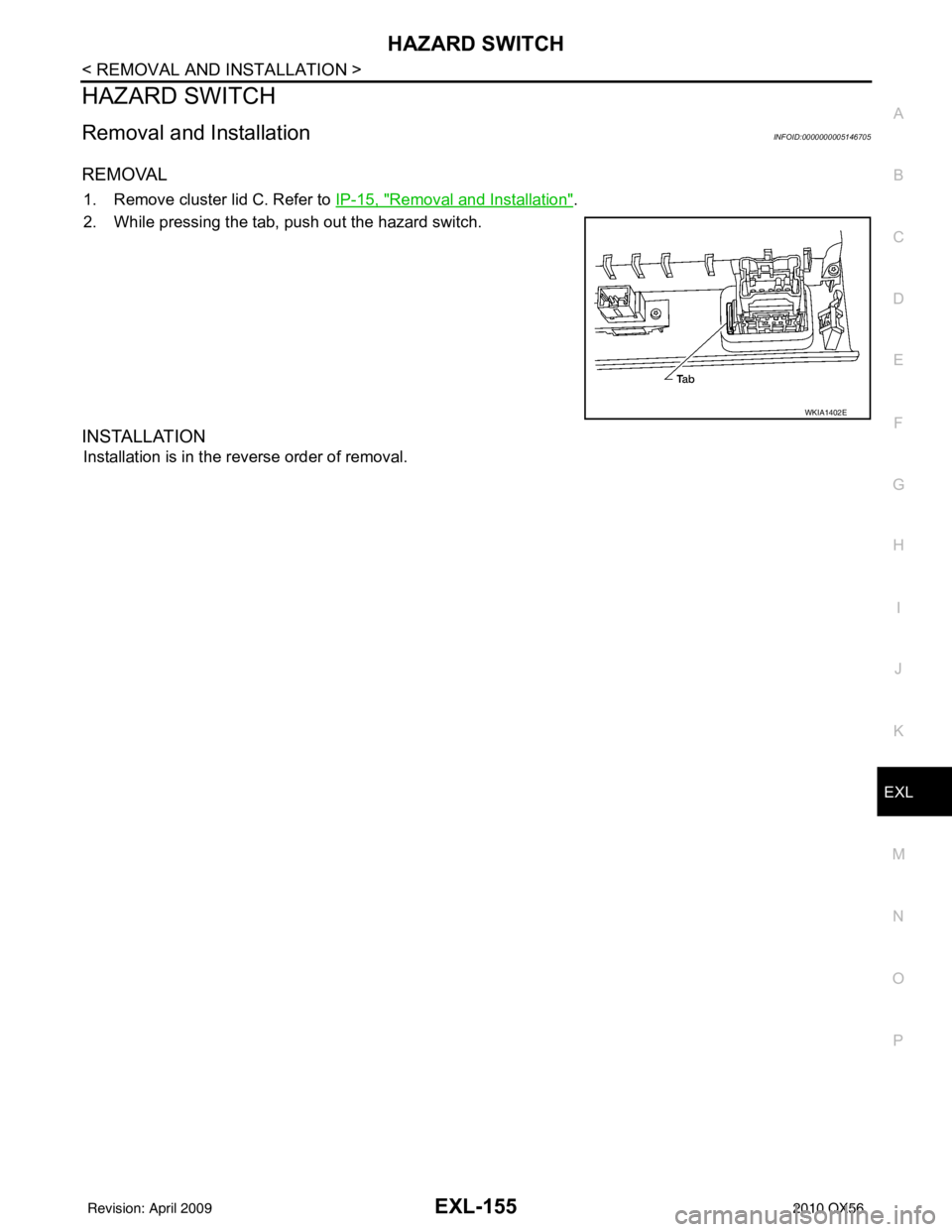
Removal and InstallationINFOID:0000000005146705
REMOVAL
1. Remove cluster lid C. Refer to IP-15, "Removal and Installation".
2. While pressing the tab, push out the hazard switch.
INSTALLATION
Installation is in the reverse order of removal.
WKIA1402E
Revision: April 20092010 QX56
Page 2142 of 4210

SQUEAK AND RATTLE TROUBLE DIAGNOSESEXT-7
< SERVICE INFORMATION >
C
DE
F
G H
I
J
L
M A
B
EXT
N
O P
SILICONE GREASE
Used instead of UHMW tape that will be visible or not fit.
Note: Will only last a few months.
SILICONE SPRAY
Use when grease cannot be applied.
DUCT TAPE
Use to eliminate movement.
CONFIRM THE REPAIR
Confirm that the cause of a noise is repaired by test driving the vehicle. Operate the vehicle under the same
conditions as when the noise originally occurred. Refer to the notes on the Diagnostic Worksheet.
Generic Squeak and Rattle TroubleshootingINFOID:0000000005147315
Refer to Table of Contents for specific component removal and installation information.
INSTRUMENT PANEL
Most incidents are caused by contact and movement between:
1. The cluster lid A and instrument panel
2. Acrylic lens and combination meter housing
3. Instrument panel to front pillar garnish
4. Instrument panel to windshield
5. Instrument panel pins
6. Wiring harnesses behind the combination meter
7. A/C defroster duct and duct joint
These incidents can usually be located by tapping or moving the components to duplicate the noise or by
pressing on the components while driving to stop the noi se. Most of these incidents can be repaired by apply-
ing felt cloth tape or silicone spray (in hard to reach areas). Urethane pads can be used to insulate wiring har-
ness.
CAUTION:
Do not use silicone spray to isolate a squeak or ra ttle. If you saturate the area with silicone, you will
not be able to recheck the repair.
CENTER CONSOLE
Components to pay attention to include:
1. Shifter assembly cover to finisher
2. A/C control unit and cluster lid C
3. Wiring harnesses behind audio and A/C control unit
The instrument panel repair and isolation pr ocedures also apply to the center console.
DOORS
Pay attention to the:
1. Finisher and inner panel making a slapping noise
2. Inside handle escutcheon to door finisher
3. Wiring harnesses tapping
4. Door striker out of alignment causing a popping noise on starts and stops
Tapping or moving the components or pressing on them while driving to duplicate the conditions can isolate
many of these incidents. You can usually insulate the ar eas with felt cloth tape or insulator foam blocks from
the NISSAN Squeak and Rattle Kit (J-43980) to repair the noise.
TRUNK
Trunk noises are often caused by a loose jack or loose items put into the trunk by the owner.
In addition look for:
1. Trunk lid bumpers out of adjustment
2. Trunk lid striker out of adjustment
3. The trunk lid torsion bars knocking together
4. A loose license plate or bracket
Revision: April 20092010 QX56
Page 2275 of 4210

GW-4
< SYMPTOM DIAGNOSIS >
SQUEAK AND RATTLE TROUBLE DIAGNOSIS
68370-4B000: 15×25 mm (0.59× 0.98 in) pad/68239-13E00: 5 mm (0.20 in ) wide tape roll. The following
materials not found in the kit can also be used to repair squeaks and rattles.
UHMW (TEFLON) TAPE
Insulates where slight movement is present. Ideal for inst rument panel applications.
SILICONE GREASE
Used instead of UHMW tape that will be visible or not fit.
Note: Will only last a few months.
SILICONE SPRAY
Use when grease cannot be applied.
DUCT TAPE
Use to eliminate movement.
CONFIRM THE REPAIR
Confirm that the cause of a noise is repaired by test driving the vehicle. Operate the vehicle under the same
conditions as when the noise originally occurred. Refer to the notes on the Diagnostic Worksheet.
Generic Squeak and Rattle TroubleshootingINFOID:0000000005384298
Refer to Table of Contents for specific component removal and installation information.
INSTRUMENT PANEL
Most incidents are caused by contact and movement between:
1. The cluster lid A and instrument panel
2. Acrylic lens and combination meter housing
3. Instrument panel to front pillar garnish
4. Instrument panel to windshield
5. Instrument panel mounting pins
6. Wiring harnesses behind the combination meter
7. A/C defroster duct and duct joint
These incidents can usually be located by tapping or moving the components to duplicate the noise or by
pressing on the components while driving to stop the noise. Most of these incidents can be repaired by apply-
ing felt cloth tape or silicone spray (in hard to reach areas). Urethane pads can be used to insulate wiring har-
ness.
CAUTION:
Do not use silicone spray to isolate a squeak or rattle. If you saturate the ar ea with silicone, you will
not be able to recheck the repair.
CENTER CONSOLE
Components to pay attention to include:
1. Shifter assembly cover to finisher
2. A/C control unit and cluster lid C
3. Wiring harnesses behind audio and A/C control unit
The instrument panel repair and isolation pr ocedures also apply to the center console.
DOORS
Pay attention to the:
1. Finisher and inner panel making a slapping noise
2. Inside handle escutcheon to door finisher
3. Wiring harnesses tapping
4. Door striker out of alignment causing a popping noise on starts and stops
Tapping or moving the components or pressing on them wh ile driving to duplicate the conditions can isolate
many of these incidents. You can usually insulate the areas with felt cloth tape or insulator foam blocks from
the NISSAN Squeak and Rattle Kit (J-43980) to repair the noise.
TRUNK
Trunk noises are often caused by a loose jack or loose items put into the trunk by the owner.
In addition look for:
1. Trunk lid bumpers out of adjustment
Revision: April 20092010 QX56