Page 49 of 207

1FEATURES OF YOUR HYUNDAI
48
!WARNING:
o Make sure to refuel your vehicle according to the "Fuel require- ments" suggested in section 1.
o Fuel vapors are dangerous. Be-
fore refueling, always stop theengine and never allow sparks or open flames near the tank area. If you need to replace the tank cap,use a genuine Hyundai replace- ment part. If you open the fuel tank cap dur-ing high ambient temperatures, a slight "pressure sound" may be heard. This is normal and not acause for concern. Whenever you open the fuel tank cap, turn it slowly.
o Automotive fuels are flammable/ explosive materials. When refuel-ing, please note the followingguidelines carefully.
- Before touching the fuel nozzle or
fuel tank cap, have one's hands incontact with metal parts away from the tank neck to discharge static electricity.
FUEL TANK CAP
B560A03HR-GAT
The fuel tank cap is located at the left side of the vehicle body. The fuel tank cap can be unlocked by turning the key counterclockwise.To lock the fuel tank cap, turn it clock- wise until it locks into place. NOTE: If the fuel tank cap will not open because ice has formed around it, tap lightly on the cap to break the iceand release the cap. If necessary, spray around the cap with an ap- proved de-icer fluid (do not use ra-diator anti-freeze) or move the ve- hicle to a warm place and allow the ice to melt. HHR2036
- Do not get back in the vehicle
while refueling. Do not operateanything that can produce static electricity. Static electricity dis- charge can ignite fuel vapors re-sulting in an explosion.
- When using a portable fuel con-
tainer, be sure to place the con-tainer on the ground while refuel- ing. Static electricity discharge from the container can ignite fuelvapors causing a fire. While start- ing refueling, contact should be maintained until the filling is com-plete.
- Do not use cellular phones around
a gas station. The electric currentor electronic interference from cel- lular phones can ignite fuel va- pors causing a fire.
- When refueling, always turn the engine off. Sparks by engine com-partment electrical equipment canignite fuel vapors causing a fire. After refueling, check to make sure the fuel tank cap is securely closed,and then start the engine.
- Do not smoke or try to light ciga-
rettes around a gas station. Auto-motive fuels are flammable.
Page 50 of 207
1
FEATURES OF YOUR HYUNDAI
49SIDE GATE
B191B01HR-GAT To open the side gate
1. With the rear gate opened, pull up the knob to release the support bar down. HHR2026
Support bar
!WARNING:
When the rear combination lamps are hidden, other road users shouldbe warned by means of warning tri- angle or other devices. To close the rear gate
Lift the rear gate up and lock the rear gate handle in place. HHR2031
2. Lower the rear gate slowly with it
received on both arms.
REAR GATE
B191A01HR-GAT To open the rear gate
HHR2025
1. Lift up the rear gate handle, push it inside and pull it toward you.
OHR028106
Page 51 of 207
1FEATURES OF YOUR HYUNDAI
50
OHR028119
2. Push the knob down to lock the side gates.
2. Remove the side gate handle from
the hook after pulling it up.
3. Lower the side gate slowly with it
received on both arms. OHR028117
OHR028118
To close the side gate
1. Lift the side gate up and lock the side
gate handle in place.
!WARNING:
When locking the side gate handle, be careful not to get your fingers intothe chink in the handle.
Page 52 of 207

1
FEATURES OF YOUR HYUNDAI
51EXTERIOR TOOL BOX
B650A02HR-GAT (If Installed)
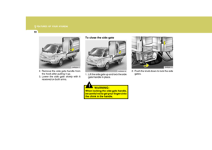
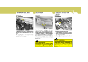
The exterior tool box is located behind the rear tire on left side to store jack and tool.To open it, pull up the clamp lever (1) and unhook the clamp. OHR048100
(1)
!
STEERING WHEEL TILT LEVER
B600A01HR-AAT (If Installed)
To Adjust the Steering Wheel:
1. Push the lever and hold it to unlock.
2. Raise or lower the steering wheel to the desired position.
3. After adjustment, release the lever.
WARNING:
Do not attempt to adjust the steering wheel while driving as this may re-sult in loss of control of the vehicle which may cause serious injury or death. OHR028108
!
SUN VISOR
Your Hyundai is equipped with sun visors to give the driver and front pas- senger either frontal or sideward shade. To reduce glare or to shut out directrays of the sun, turn the sun visor down. Ticket holders are provided on the back of the sun visor for the driver and frontpassenger.
B580A01HR-GAT
OHR028107
WARNING:
Do not place the sun visor in such amanner that it obscures visibility of the roadway, traffic or other objects.
Page 53 of 207
1FEATURES OF YOUR HYUNDAI
52HORN
B610B01A-GAT
Press the center hub of the steering wheel to sound the horn. B610B01HR
Page 54 of 207
1
FEATURES OF YOUR HYUNDAI
53HEATING AND COOLING CONTROL
B710A01TB-GAT (If Installed)
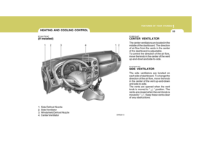
1. Side Defrost Nozzle
2. Side Ventilator
3. Windshield Defrost Nozzle
4. Center Ventilator B710B01S-AAT CENTER VENTILATOR The center ventilators are located in the middle of the dashboard. The directionof air flow from the vents in the center of the dashboard is adjustable. To control the direction of the air flow,move the knob in the center of the vent up-and-down and side-to-side. B710C02HP-AAT SIDE VENTILATOR The side ventilators are located on each side of dashboard. To change thedirection of the air flow, move the knob in the center of the vent up-and-down and side-to-side.The vents are opened when the vent knob is moved to " " position. The vents are closed when the vent knob ismoved to " ". Keep these vents clear of any obstructions.
OHR028110
Page 55 of 207
1FEATURES OF YOUR HYUNDAI
54
Face-Level
Selecting the "Face" mode will cause air to be discharged through the face level vents.
B670D01HR-GAT Air Flow Control This is used to direct the flow of air. Air can be directed to the floor, dashboard outlets, or windshield. Five symbolsare used to represent Face, Bi-Level, Floor, Floor-Defrost and Defrost air position. OHR028111
HHR2080
HEATING AND VENTILATION
B670A01HR-GAT
(If Installed)
1. Air flow control switch
2. Fan speed control switch
3. Temperature control switch
4. Air intake control switch
5. Air conditioning switch HHR2017
1
2
3
4
5
Page 56 of 207
1
FEATURES OF YOUR HYUNDAI
55
Bi-Level
Air is discharged through the face vents and the floor vents. This makes it possible to have cooler air from the dashboard vents and warmer air fromthe floor outlets at the same time. Floor-Level
Air is discharged through the floorvents, windshield defroster nozzle, side defroster nozzle, side ventilator.Floor-Defrost Level
Air is discharged through the wind- shield defroster nozzle, the floor vents,side defroster nozzle, side ventilator.
OHR028112 OHR028113OHR028114