Page 156 of 207
5VEHICLE MAINTENANCE REQUIREMENTS
10
F060F01A-AAT
o Vacuum and Crankcase
Ventilation Hoses
Inspect the surface of hoses for evi- dence of heat and/or mechanical dam- age. Hard and brittle rubber, cracking, tears, cuts, abrasions, and excessiveswelling indicate deterioration. Particu- lar attention should be paid to examin- ing those hose surfaces nearest tohigh heat sources, such as the ex- haust manifold. Inspect the hose routing to assure that the hoses do not come in contact with any heat source, sharp edges or mov- ing component which might cause heatdamage or mechanical wear. Inspect all hose connections, such as clamps and couplings, to make sure they aresecure, and that no leaks are present. Hoses should be replaced immedi- ately if there is any evidence of dete-rioration or damage. F060B01HR-GAT
o Drive Belts
Inspect all drive belts (water pump andalternator) for evidence of cuts, cracks, excessive wear or oiliness, and re- place if necessary. Drive belts shouldbe checked periodically for proper ten- sion and adjusted as necessary. F060E01A-GAT
o Timing Belt
Inspect all parts related with the timing
belt for damage and deformation. Re- place any damaged parts immediately.
F060H01A-AAT
o Air Cleaner Filter
A Genuine Hyundai air cleaner filter isrecommended when the filter is re-placed.
F060G01A-AAT
o Vapor Hose and Fuel Filler Cap
The vapor hose and fuel filler cap
should be inspected at those intervals specified in the maintenance sched- ule. Make sure that a new vapor hoseor fuel filler cap is correctly replaced.
F070B01A-GAT
o Cooling System
Check the cooling system part, suchas radiator, coolant reservoir, hoses and connections for leakage and dam- age. Replace any damaged parts. F070C01A-AAT
o Coolant
The coolant should be changed at the intervals specified in the mainte- nance schedule. F070D01HP-GAT
o Manual Transmission Oil
Inspect the manual transmission oil
according to the maintenance sched- ule. NOTE:
If the oil level is low, check for
possible leaks before adding oil. Do not overfill.
Page 159 of 207

Front Open Service Panel ............................................ 6-2
Engine Compartment .................................................... 6-3
General Checks ........................................................... 6-5
Checking the Engine Oil ............................................... 6-6
Changing the Oil and Filter ........................................... 6-8
Checking and Changing the Engine Coolant ...............6-10
Changing the Air Cleaner Filte r ....................................6-12
Checking the Transmission Oil (Manual) ....................6-15
Checking the Rear Axle Oil......................................... 6-16
Checking the B rakes ................................................... 6-17
Air Conditioning Care ................................................... 6-18
Checking the Climate Control Air Filter
(For Evaporator and Blower U nit) .............................6-19
Checking Drive Belts................................................... 6-21
Checking and Replacing Fuses .................................. 6-22
Checking the Battery ................................................... 6-24
Power Steering Fluid Level .......................................... 6-26
Fuel Fil ter ..................................................................... 6-27
Replacement of Light Bulbs ......................................... 6-30
Bulb Wattages ............................................................. 6-37
Fuse Panel Description ............................................... 6-38
DO-IT-YOURSELF MAINTENANCE
6
6
Page 161 of 207
6
DO-IT-YOURSELF MAINTENANCE
3ENGINE COMPARTMENT
1. Power Steering Fluid Reservoir (If Installed)
2. Engine Oil Filler Cap 3. Engine Oil Level Dipstick
4. Fuel Filter
G010B01HR-GAT Diesel Engine (2.6 N/A)
G010B01HR
5. Fuse and Relay Box
6. Radiator CapCAUTION:
To inspect or service the en-gine, first move the front seat.(Refer to " To Access the En- gine" on page 1-12).
!
Page 162 of 207
6 DO-IT-YOURSELF MAINTENANCE
4
G010C01HR-GAT Diesel Engine (2.5 TCI)
HHR5001
1. Power Steering Fluid Reservoir (If Installed)
2. Engine Oil Filler Cap 3. Engine Oil Level Dipstick
4. Fuel Filter CAUTION:
o To inspect or service the engine, first move the front seat. (Refer to " To Access the Engine" on page 1-12).
o When inspecting or servic- ing the engine, you shouldhandle tools and other heavy objects carefully so that the plastic cover of theengine is not damaged.
!
5. Fuse and Relay Box
6. Radiator Cap
Page 185 of 207
6
DO-IT-YOURSELF MAINTENANCE
27
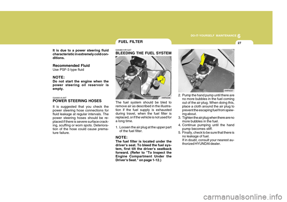
G350B01HR-GAT BLEEDING THE FUEL SYSTEM
The fuel system should be bled to remove air as described in the illustra-tion if the fuel supply is exhausted during travel, when the fuel filter is replaced, or if the vehicle is not used fora long time.
1. Loosen the air plug at the upper part of the fuel filter.
NOTE: The fuel filter is located under the driver's seat. To bleed the fuel sys- tem, first tilt the driver's seatback forward. (Refer to "To Inspect theEngine Compartment Under the Driver's Seat." on page 1-12.) HHR4046
2. Pump the hand pump until there are
no more bubbles in the fuel coming out of the air plug. When doing this,place a cloth around the air plug to prevent the escaping fuel from spew- ing about.
3. Tighten the air plug when there are no more bubbles in the fuel.
4. Continue pumping until the hand
pump becomes stiff.
5. Finally, check to be sure that there is
no leakage of fuel.If in doubt, consult your nearest au- thorized HYUNDAI dealer. HHR4047
FUEL FILTER
G240A01A-AAT POWER STEERING HOSES It is suggested that you check the power steering hose connections for fluid leakage at regular intervals. The power steering hoses should be re-placed if there is severe surface crack- ing, scuffing or worn spots. Deteriora- tion of the hose could cause prema-ture failure.
It is due to a power steering fluidcharacteristic in extremely cold con-ditions. Recommended Fluid Use PSF-3 type fluid NOTE: Do not start the engine when the power steering oil reservoir is empty.
Page 186 of 207
6 DO-IT-YOURSELF MAINTENANCE
28
!WARNING:
o Do not smoke or have any other open flame near the vehicle while bleeding the fuel system.
o Be sure to carefully clean away
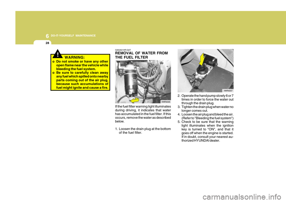
any fuel which spilled onto nearbyparts coming out of the air plug, because such accumulations of fuel might ignite and cause a fire. G300A01HR-GAT REMOVAL OF WATER FROM THE FUEL FILTER
HHR4045
If the fuel filter warning light illuminates during driving, it indicates that waterhas accumulated in the fuel filter. If this occurs, remove the water as described below.
1. Loosen the drain plug at the bottom of the fuel filter. HHR4047
2. Operate the hand pump slowly 6 or 7 times in order to force the water out through the drain plug.
3. Tighten the drain plug when water no longer comes out.
4. Loosen the air plug and bleed the air. (Refer to "Bleeding the fuel system")
5. Check to be sure that the warning
light illuminates when the ignition key is turned to "ON", and that it goes off when the engine is started. If in doubt, consult your nearest au-thorized HYUNDAI dealer.
Page 187 of 207
6
DO-IT-YOURSELF MAINTENANCE
29
!WARNING:
o Do not smoke or have any other open flame near the vehicle while bleeding the fuel system.
o Be sure to carefully wipe away any
water drained out in this manner,because the fuel mixed in the wa- ter might be ignited and result in a fire.
HEADLIGHT AIMING ADJUSTMENT
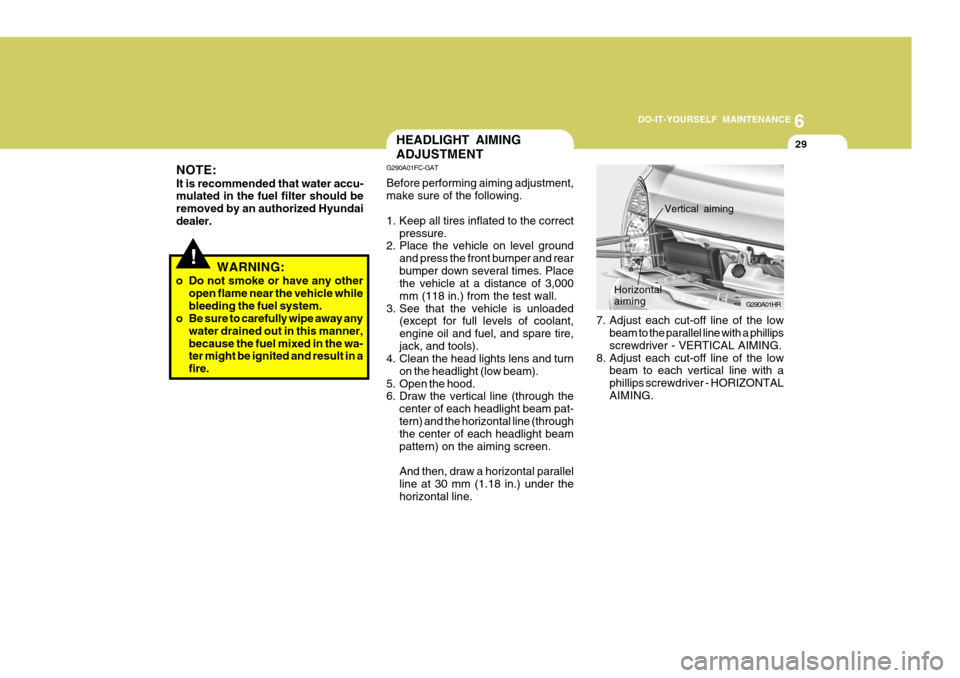
7. Adjust each cut-off line of the lowbeam to the parallel line with a phillips screwdriver - VERTICAL AIMING.
8. Adjust each cut-off line of the low beam to each vertical line with a phillips screwdriver - HORIZONTALAIMING. G290A01HR
Horizontal aiming
Vertical aiming
G290A01FC-GAT Before performing aiming adjustment, make sure of the following.
1. Keep all tires inflated to the correct
pressure.
2. Place the vehicle on level ground
and press the front bumper and rear bumper down several times. Place the vehicle at a distance of 3,000 mm (118 in.) from the test wall.
3. See that the vehicle is unloaded (except for full levels of coolant,engine oil and fuel, and spare tire,jack, and tools).
4. Clean the head lights lens and turn
on the headlight (low beam).
5. Open the hood.
6. Draw the vertical line (through the
center of each headlight beam pat- tern) and the horizontal line (through the center of each headlight beam pattern) on the aiming screen. And then, draw a horizontal parallel line at 30 mm (1.18 in.) under thehorizontal line.
NOTE: It is recommended that water accu- mulated in the fuel filter should be removed by an authorized Hyundaidealer.
Page 198 of 207
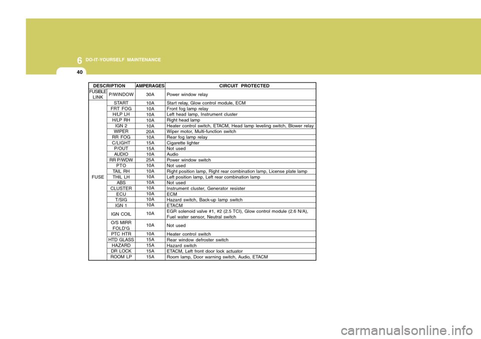
6 DO-IT-YOURSELF MAINTENANCE
40
AMPERAGES30A 10A 10A10A 10A 10A 20A 10A 15A 15A 10A 25A 10A 10A 10A 10A 10A 10A 10A 10A 10A 10A 10A 15A15A15A15A CIRCUIT PROTECTED
Power window relay
Start relay, Glow control module, ECM Front fog lamp relayLeft head lamp, Instrument cluster Right head lamp
Heater control switch, ETACM, Head lamp leveling switch, Blower relay
Wiper motor, Multi-function switch Rear fog lamp relay Cigarette lighterNot used Audio
Power window switchNot used Right position lamp, Right rear combination lamp, License plate lamp Left position lamp, Left rear combination lampNot used
Instrument cluster, Generator resister ECMHazard switch, Back-up lamp switch
ETACM
EGR solenoid valve #1, #2 (2.5 TCI), Glow control module (2.6 N/A),
Fuel water sensor, Neutral switch Not usedHeater control switch Rear window defroster switch Hazard switch
ETACM, Left front door lock actuator
Room lamp, Door warning switch, Audio, ETACM
P/WINDOW START
FRT FOG
H/LP LH
H/LP RH IGN 2
WIPER
RR FOG C/LIGHT P/OUT
AUDIO
RR P/WDW
PTO
TAIL RH THIL LH ABS
CLUSTER ECU
T/SIG IGN 1
IGN COIL
O/S MIRR FOLD'G
PTC HTR
HTD GLASS HAZARD
DR LOCK
ROOM LP
DESCRIPTION
FUSIBLE LINK
FUSE

